Page 1242 of 4366
CO-52
[VK45DE]
WATER PUMP
Revision: 2006 July 2007 FX35/FX45
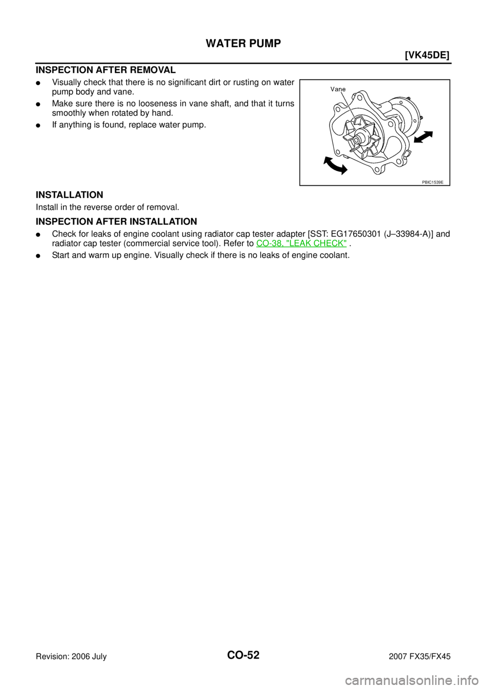
INSPECTION AFTER REMOVAL
�Visually check that there is no significant dirt or rusting on water
pump body and vane.
�Make sure there is no looseness in vane shaft, and that it turns
smoothly when rotated by hand.
�If anything is found, replace water pump.
INSTALLATION
Install in the reverse order of removal.
INSPECTION AFTER INSTALLATION
�Check for leaks of engine coolant using radiator cap tester adapter [SST: EG17650301 (J–33984-A)] and
radiator cap tester (commercial service tool). Refer to CO-38, "
LEAK CHECK" .
�Start and warm up engine. Visually check if there is no leaks of engine coolant.
PBIC1539E
Page 1243 of 4366
THERMOSTAT AND WATER CONTROL VALVE CO-53
[VK45DE]
C
D E
F
G H
I
J
K L
M A
CO
Revision: 2006 July 2007 FX35/FX45
THERMOSTAT AND WATER CONTROL VALVEPFP:21200
ComponentsNBS005S1
1. O-ring 2. Water outlet pipe 3. Thermostat housing
4. Radiator cap 5. Radiator hose (upper) 6. Water hose
7. Water hose 8. Water pipe 9. Water hose
10. Water hose 11. Thermostat 12. Rubber ring
13. Water inlet 14. Water suction hose 15. Water suction pipe
16. Radiator hose (lower) 17. Water hose 18. Water hose
19. O-ring 20. Heater pipe 21. Heater hose
22. Gasket 23. Water outlet 24. Water control valve
25. Rubber ring 26. O-ring 27. Water connector
28. Heater hose 29. Gasket
A. To radiator B. To oil cooler C. To cylinder block
PBIC4557E
Page 1244 of 4366
![INFINITI FX35 2007 Service Manual CO-54
[VK45DE]
THERMOSTAT AND WATER CONTROL VALVE
Revision: 2006 July 2007 FX35/FX45
�Refer to GI-11, "Components" for symbol marks in the figure.
Removal and InstallationNBS003KS
REMOVAL
1. Drain en](/manual-img/42/57018/w960_57018-1243.png "INFINITI FX35 2007 Service Manual CO-54
[VK45DE]
THERMOSTAT AND WATER CONTROL VALVE
Revision: 2006 July 2007 FX35/FX45
�Refer to GI-11, \"Components\" for symbol marks in the figure.
Removal and InstallationNBS003KS
REMOVAL
1. Drain en")
CO-54
[VK45DE]
THERMOSTAT AND WATER CONTROL VALVE
Revision: 2006 July 2007 FX35/FX45
�Refer to GI-11, "Components" for symbol marks in the figure.
Removal and InstallationNBS003KS
REMOVAL
1. Drain engine coolant from drain plugs on radiator and both side of cylinder block. Refer to CO-38, "Chang-
ing Engine Coolant" and EM-249, "DISASSEMBLY" .
CAUTION:
�Perform this step when engine is cold.
�Do not spill engine coolant on drive belts.
2. Remove engine cover with power tool. Refer to EM-173, "
ENGINE ROOM COVER" .
3. Remove air duct (inlet). Refer to EM-177, "
AIR CLEANER AND AIR DUCT" .
4. Disconnect water suction hose from water inlet.
5. Remove water inlet and thermostat. CAUTION:
Do not disassemble thermostat.
6. Remove intake manifolds (upper and lower). Refer to EM-179, "
INTAKE MANIFOLD" .
7. Disconnect radiator hose (upper) and water hoses from thermostat housing.
8. Disconnect heater hoses from water outlet and heater pipe.
9. Remove thermostat housing, water outlet pipe, water connector, water control valve, water outlet and heater pipe.
CAUTION:
Do not disassemble water control valve.
INSPECTION AFTER REMOVAL
�Make sure that valves both in thermostat and water control valve are completely closing at normal temper-
ature.
�Place a thread so that it is caught in the valves of the thermostat
and water control valve. Immerse fully in a container filled with
water. Heat while stirring. (The example in the figure shows ther-
mostat.)
�The valve opening temperature is the temperature at which the
valve opens and falls from the thread.
�Continue heating. Check the maximum valve lift.
NOTE:
The maximum valve lift standard temperature for water control
valve is the reference value.
� After checking the maximum valve lift, lower the water tempera-
ture and check the valve closing temperature.
Standard values:
�If the malfunctioning condition, when closing valve at normal temperature, or measured values are out of
the standard, replace thermostat and/or water control valve.
INSTALLATION
Note the following, and install in the reverse order of removal.
CAUTION:
Be careful not to spill engine coolant over engine room. Use rag to absorb engine coolant.
D. To heater core E. To cylinder head (left bank) F. To cylinder head (right bank)
G. To intake manifold adapter
SLC252B
Thermostat Water control valve
Valve opening temperature 80 - 84 °C (176 - 183 °F) 93.5 - 96.5 °C (200 - 206 °F)
Maximum valve lift More than 10 mm/ 95
°C
(0.39 in/ 203 °F) More than 8 mm/ 108
°C
(0.315 in/ 226 °F)
Valve closing temperature 77 °C (171 °F) 90 °C (194 °F)
Page 1245 of 4366
![INFINITI FX35 2007 Service Manual THERMOSTAT AND WATER CONTROL VALVE CO-55
[VK45DE]
C
D E
F
G H
I
J
K L
M A
CO
Revision: 2006 July 2007 FX35/FX45
Thermostat and Water Control Valve
�Install thermostat and water control va](/manual-img/42/57018/w960_57018-1244.png "INFINITI FX35 2007 Service Manual THERMOSTAT AND WATER CONTROL VALVE CO-55
[VK45DE]
C
D E
F
G H
I
J
K L
M A
CO
Revision: 2006 July 2007 FX35/FX45
Thermostat and Water Control Valve
�Install thermostat and water control va")
THERMOSTAT AND WATER CONTROL VALVE CO-55
[VK45DE]
C
D E
F
G H
I
J
K L
M A
CO
Revision: 2006 July 2007 FX35/FX45
Thermostat and Water Control Valve
�Install thermostat and water control valve with the whole circum-
ference of each flange part fit securely inside rubber ring. (The
example in the figure shows thermostat.)
�Install thermostat with jiggle valve facing upwards. (The position
deviation may be within the range of ±10 degrees)
�Install water control valve with the up-mark facing up and the
frame center part facing upwards. (The position deviation may
be within the range of ±10 degrees)
Water Outlet Pipe and Heater Pipe
First apply a neutral detergent to O-rings, then quickly insert the insertion parts of the water outlet pipe and
heater pipe into the installation holes.
INSPECTION AFTER INSTALLATION
�Check for leaks of engine coolant using radiator cap tester adapter [SST: EG17650301 (J33984-A)] and
radiator cap tester (commercial service tool). Refer to CO-38, "
LEAK CHECK" .
�Start and warm up engine. Visually check if there is no leaks of engine coolant.
PBIC0157E
PBIC0158E
Page 1246 of 4366
CO-56
[VK45DE]
SERVICE DATA AND SPECIFICATIONS (SDS)
Revision: 2006 July 2007 FX35/FX45
SERVICE DATA AND SPECIFICATIONS (SDS)PFP:00030
Standard and LimitNBS003KT
ENGINE COOLANT CAPACITY (APPROXIMATE)
Unit: (US qt, Imp qt)
RADIATOR
Unit: kPa (kg/cm2 , psi)
THERMOSTAT
WATER CONTROL VALVE
Engine coolant capacity [With reservoir tank at (“MAX” level)] 10.0 (10-5/8, 8-3/4)
Reservoir tank engine coolant capacity (at “MAX” level) 0.8 (7/8, 3/4)
Radiator cap relief pressure Standard 78 - 98 (0.8 - 1.0, 11 - 14)
Limit 59 (0.6, 9)
Leakage testing pressure 157 (1.6, 23)
Valve opening temperature 80 - 84 °C (176 - 183 °F)
Maximum valve lift More than 10 mm/ 95 °C (0.39 in/ 203 °F)
Valve closing temperature 77 °C (171 °F)
Valve opening temperature 93.5 - 96.5 °C (200 - 206 °F)
Maximum valve lift More than 8 mm/ 108 °C (0.315 in/ 226 °F)
Valve closing temperature 90 °C (194 °F)
Page 1475 of 4366
![INFINITI FX35 2007 Service Manual TROUBLE DIAGNOSIS EC-99
[VQ35DE]
C
D E
F
G H
I
J
K L
M A
EC
Revision: 2006 July 2007 FX35/FX45
1 - 6: The numbers refer to the order of inspection. Va l v e
mecha-
nism Timing chain](/manual-img/42/57018/w960_57018-1474.png "INFINITI FX35 2007 Service Manual TROUBLE DIAGNOSIS EC-99
[VQ35DE]
C
D E
F
G H
I
J
K L
M A
EC
Revision: 2006 July 2007 FX35/FX45
1 - 6: The numbers refer to the order of inspection. Va l v e
mecha-
nism Timing chain")
TROUBLE DIAGNOSIS EC-99
[VQ35DE]
C
D E
F
G H
I
J
K L
M A
EC
Revision: 2006 July 2007 FX35/FX45
1 - 6: The numbers refer to the order of inspection. Va l v e
mecha-
nism Timing chain
55555 55 5 EM-64
Camshaft
EM-83
Intake valve timing controlEM-64
Intake valve
3 EM-101
Exhaust valve
Exhaust Exhaust manifold/Tube/Muffler/ Gasket 55555 55 5 EM-26
,
EX-
3Three way catalyst
Lubrica-
tion Oil pan/Oil strainer/Oil pump/Oil
filter/Oil gallery/Oil cooler 55555 55 5 EM-30
,
LU-
17 , LU-10 ,
LU-14
Oil level (Low)/Filthy oil LU-7
Cooling
Radiator/Hose/Radiator filler cap
55555 55 45 CO-14,
CO-17
Thermostat 5 CO-27
Water pumpCO-22
Water galleryCO-29
Cooling fan 5EC-227
Coolant level (Low)/Contami-
nated coolant 5
CO-11
IVIS (Infiniti Vehicle Immobilizer System —
NATS) 11
EC-52 or
BL-205
SYMPTOM
Reference
page
HARD/NO START/RESTART (EXCP. HA)
ENGINE STALL
HESITATION/SURGING/FLAT SPOT
SPARK KNOCK/DETONATION
LACK OF POWER/POOR ACCELERATION
HIGH IDLE/LOW IDLE
ROUGH IDLE/HUNTING
IDLING VIBRATION
SLOW/NO RETURN TO IDLE
OVERHEATS/WATER TEMPERATURE HIGH
EXCESSIVE FUEL CONSUMPTION
EXCESSIVE OIL CONSUMPTION
BATTERY DEAD (UNDER CHARGE)
Warranty symptom code AA AB AC AD AE AF AG AH AJ AK AL AM HA
Page 1599 of 4366
![INFINITI FX35 2007 Service Manual DTC P0125 ECT SENSOR EC-223
[VQ35DE]
C
D E
F
G H
I
J
K L
M A
EC
Revision: 2006 July 2007 FX35/FX45
3. CHECK THERMOSTAT OPERATION
When the engine is cold [lower than 70 °C (158 °F)] co](/manual-img/42/57018/w960_57018-1598.png "INFINITI FX35 2007 Service Manual DTC P0125 ECT SENSOR EC-223
[VQ35DE]
C
D E
F
G H
I
J
K L
M A
EC
Revision: 2006 July 2007 FX35/FX45
3. CHECK THERMOSTAT OPERATION
When the engine is cold [lower than 70 °C (158 °F)] co")
DTC P0125 ECT SENSOR EC-223
[VQ35DE]
C
D E
F
G H
I
J
K L
M A
EC
Revision: 2006 July 2007 FX35/FX45
3. CHECK THERMOSTAT OPERATION
When the engine is cold [lower than 70 °C (158 °F)] condition, grasp lower radiator hose and confirm the engine
coolant does not flow.
OK or NG
OK >> GO TO 4.
NG >> Repair or replace thermostat. Refer to CO-27, "
WATER INLET AND THERMOSTAT ASSEMBLY"
.
4. CHECK INTERMITTENT INCIDENT
Refer to EC-147, "
TROUBLE DIAGNOSIS FOR INTERMITTENT INCIDENT" .
Refer to EC-211, "
Wiring Diagram" .
>> INSPECTION END
Component InspectionNBS003OA
ENGINE COOLANT TEMPERATURE SENSOR
Check resistance between engine coolant temperature sensor termi-
nals 1 and 2 as shown in the figure.
If NG, replace engine coolant temperature sensor.
Removal and InstallationNBS003OB
ENGINE COOLANT TEMPERATURE SENSOR
Refer to CO-27, "WATER INLET AND THERMOSTAT ASSEMBLY" .
PBIB2005E
Engine coolant temperature °C ( °F) Resistance k Ω
20 (68) 2.1 - 2.9
50 (122) 0.68 - 1.00
90 (194) 0.236 - 0.260
SEF012P
Page 1874 of 4366
![INFINITI FX35 2007 Service Manual EC-498
[VQ35DE]
DTC P1217 ENGINE OVER TEMPERATURE
Revision: 2006 July 2007 FX35/FX45
CAUTION:
When a malfunction is indicated, be sure to replace the coolant. Refer to CO-11, "
Changing Engine
Cool](/manual-img/42/57018/w960_57018-1873.png "INFINITI FX35 2007 Service Manual EC-498
[VQ35DE]
DTC P1217 ENGINE OVER TEMPERATURE
Revision: 2006 July 2007 FX35/FX45
CAUTION:
When a malfunction is indicated, be sure to replace the coolant. Refer to CO-11, \"
Changing Engine
Cool")
EC-498
[VQ35DE]
DTC P1217 ENGINE OVER TEMPERATURE
Revision: 2006 July 2007 FX35/FX45
CAUTION:
When a malfunction is indicated, be sure to replace the coolant. Refer to CO-11, "
Changing Engine
Coolant" . Also, replace the engine oil. Refer to LU-9, "Changing Engine Oil" .
1. Fill radiator with coolant up to specified level with a filling speed of 2 liters per minute. Be sure to use coolant with the proper mixture ratio. Refer to MA-13, "
Anti-Freeze Coolant Mixture Ratio" .
2. After refilling coolant, run engine to ensure that no water-flow noise is emitted.
Overall Function CheckNBS003UK
Use this procedure to check the overall function of the cooling fan. During this check, a DTC might not be con-
firmed.
WARNING:
Never remove the radiator cap when the engine is hot. Serious burns could be caused by high pres-
sure fluid escaping from the radiator.
Wrap a thick cloth around cap. Carefully remove the cap by turning it a quarter turn to allow built-up
pressure to escape. Then turn the cap all the way off.
WITH CONSULT-II
1. Check the coolant level in the reservoir tank and radiator. Allow engine to cool before checking coolant level.
If the coolant level in the reservoir tank and/or radiator is below
the proper range, skip the following steps and go to EC-502,
"PROCEDURE A" .
2. Confirm whether customer filled the coolant or not. If customer filled the coolant, skip the following steps and go to EC-502,
"PROCEDURE A" .
3. Turn ignition switch ON.
4. Perform “COOLING FAN” in “ACTIVE TEST” mode with CON- SULT-II.
5. If the results are NG, go to EC-504, "
PROCEDURE B" .
DTC No. Trouble diagnosis name DTC detecting condition Possible cause
P1217
1217 Engine over tempera-
ture (Overheat)
�Cooling fan does not operate properly (Over-
heat).
�Cooling fan system does not operate prop-
erly (Overheat).
�Engine coolant level was not added to the
system using the proper filling method.
�Engine coolant is not within the specified
range.
�Harness or connectors
(Cooling fan circuit is open or shorted.)
�IPDM E/R
�Cooling fan
�Radiator hose
�Radiator
�Radiator cap
�Water pump
�Thermostat
For more information, refer to EC-507,
"Main 12 Causes of Overheating" .
SEF621W
SEF646X
![INFINITI FX35 2007 Service Manual THERMOSTAT AND WATER CONTROL VALVE CO-53
[VK45DE]
C
D E
F
G H
I
J
K L
M A
CO
Revision: 2006 July 2007 FX35/FX45
THERMOSTAT AND WATER CONTROL VALVEPFP:21200
ComponentsNBS005S1
1. O-ring 2.](/manual-img/42/57018/w960_57018-1242.png "INFINITI FX35 2007 Service Manual THERMOSTAT AND WATER CONTROL VALVE CO-53
[VK45DE]
C
D E
F
G H
I
J
K L
M A
CO
Revision: 2006 July 2007 FX35/FX45
THERMOSTAT AND WATER CONTROL VALVEPFP:21200
ComponentsNBS005S1
1. O-ring 2.")
![INFINITI FX35 2007 Service Manual CO-56
[VK45DE]
SERVICE DATA AND SPECIFICATIONS (SDS)
Revision: 2006 July 2007 FX35/FX45
SERVICE DATA AND SPECIFICATIONS (SDS)PFP:00030
Standard and LimitNBS003KT
ENGINE COOLANT CAPACITY (APPROXIMATE)](/manual-img/42/57018/w960_57018-1245.png "INFINITI FX35 2007 Service Manual CO-56
[VK45DE]
SERVICE DATA AND SPECIFICATIONS (SDS)
Revision: 2006 July 2007 FX35/FX45
SERVICE DATA AND SPECIFICATIONS (SDS)PFP:00030
Standard and LimitNBS003KT
ENGINE COOLANT CAPACITY (APPROXIMATE)")