Page 1203 of 4366
![INFINITI FX35 2007 Service Manual ENGINE COOLANT CO-13
[VQ35DE]
C
D E
F
G H
I
J
K L
M A
CO
Revision: 2006 July 2007 FX35/FX45
�If necessary, refill radiator up to filler neck with engine coolant.
8. Refill reservoir tank](/manual-img/42/57018/w960_57018-1202.png "INFINITI FX35 2007 Service Manual ENGINE COOLANT CO-13
[VQ35DE]
C
D E
F
G H
I
J
K L
M A
CO
Revision: 2006 July 2007 FX35/FX45
�If necessary, refill radiator up to filler neck with engine coolant.
8. Refill reservoir tank")
ENGINE COOLANT CO-13
[VQ35DE]
C
D E
F
G H
I
J
K L
M A
CO
Revision: 2006 July 2007 FX35/FX45
�If necessary, refill radiator up to filler neck with engine coolant.
8. Refill reservoir tank to “MAX” level line with engine coolant.
9. Repeat steps 4 through 7 two or more times with radiator cap installed until engine coolant level no longer drops.
10. Check cooling system for leaks with engine running.
11. Warm up the engine, and check for sound of engine coolant flow while running engine from idle up to 3,000 rpm with heater temperature controller set at several position between “COOL” and “WARM”.
�Sound may be noticeable at heater unit.
12. Repeat step 11 three times.
13. If sound is heard, bleed air from cooling system by repeating step 4 through 7 until engine coolant level no longer drops.
FLUSHING COOLING SYSTEM
1. Install reservoir tank if removed, and radiator drain plug.
If water drain plugs on cylinder block are removed, close and tighten them. Refer to EM-129,
"ASSEMBLY" .
2. Remove air relief plug on heater hose.
3. Fill radiator with water until water spills from the air relief hole, then close air relief plug. Fill radiator and reservoir tank with water and reinstall radiator cap.
4. Run the engine and warm it up to normal operating temperature.
5. Rev the engine two or three times under no-load.
6. Stop the engine and wait until it cools down.
7. Drain water from the system. Refer to CO-11, "
DRAINING ENGINE COOLANT" .
8. Repeat steps 1 through 7 until clear water begins to drain from radiator. Radiator drain plug:
: 1.18 N·m (0.12 kg-m, 10 in-lb)
SBIA0445E
Air relief plug: : 1.19 N·m (0.12 kg-m, 11 in-lb)
Page 1204 of 4366
![INFINITI FX35 2007 Service Manual CO-14
[VQ35DE]
RADIATOR
Revision: 2006 July 2007 FX35/FX45
RADIATORPFP:21400
ComponentsNBS003JW
�Refer to GI-11, "Components" for symbol marks in the figure.
Removal and InstallationNBS003JX
REMOVAL](/manual-img/42/57018/w960_57018-1203.png "INFINITI FX35 2007 Service Manual CO-14
[VQ35DE]
RADIATOR
Revision: 2006 July 2007 FX35/FX45
RADIATORPFP:21400
ComponentsNBS003JW
�Refer to GI-11, \"Components\" for symbol marks in the figure.
Removal and InstallationNBS003JX
REMOVAL")
CO-14
[VQ35DE]
RADIATOR
Revision: 2006 July 2007 FX35/FX45
RADIATORPFP:21400
ComponentsNBS003JW
�Refer to GI-11, "Components" for symbol marks in the figure.
Removal and InstallationNBS003JX
REMOVAL
WARNING:
Do not remove radiator cap when engine is hot. Serious burns could occur from high-pressure engine
coolant escaping from radiator. Wrap a thick cloth around the cap. Slowly turn it a quarter of a turn to
release built-up pressure. Carefully remove radiator cap by turning it all the way.
1. Remove front engine undercover with power tool.
2. Drain engine coolant from radiator. Refer to CO-11, "
Changing Engine Coolant" .
CAUTION:
�Perform this step when the engine is cold.
�Do not spill engine coolant on drive belts.
3. Remove air duct (inlet) and air cleaner case assembly. Refer to EM-17, "
AIR CLEANER AND AIR DUCT"
.
1. Reservoir tank cap 2. Reservoir tank 3. Reservoir tank hose
4. Clamp (reservoir tank hose) 5. Clamp (radiator hose) 6. Radiator hose (upper)
7. Radiator upper mount bracket 8. Mounting rubber (upper) 9. Radiator cap
10. Radiator 11. Mounting rubber (lower) 12. O-ring
13. Drain plug 14. Radiator hose (lower) 15. Clamp (A/T fluid cooler hose)
16. A/T fluid cooler hose 17. Radiator cooling fan assembly 18. Reservoir tank bracket
A. To A/T fluid cooler tube
PBIC4680E
Page 1205 of 4366
![INFINITI FX35 2007 Service Manual RADIATOR CO-15
[VQ35DE]
C
D E
F
G H
I
J
K L
M A
CO
Revision: 2006 July 2007 FX35/FX45
4. Remove reservoir tank and reservoir tank bracket.
5. Disconnect A/T fluid cooler hoses from radia](/manual-img/42/57018/w960_57018-1204.png "INFINITI FX35 2007 Service Manual RADIATOR CO-15
[VQ35DE]
C
D E
F
G H
I
J
K L
M A
CO
Revision: 2006 July 2007 FX35/FX45
4. Remove reservoir tank and reservoir tank bracket.
5. Disconnect A/T fluid cooler hoses from radia")
RADIATOR CO-15
[VQ35DE]
C
D E
F
G H
I
J
K L
M A
CO
Revision: 2006 July 2007 FX35/FX45
4. Remove reservoir tank and reservoir tank bracket.
5. Disconnect A/T fluid cooler hoses from radiator.
�Install blind plug to avoid leakage of A/T fluid.
6. Removal radiator hoses (upper and lower) and reservoir tank hose. CAUTION:
Be careful not to allow engine coolant to contact drive belts.
7. Remove radiator cooling fan assembly. Refer to CO-21, "
COOLING FAN" .
8. Rotate two radiator upper mount brackets 90 degrees in the direction shown in the figure, and remove them.
9. Lift up and remove radiator. CAUTION:
Do not damage or scratch A/C condenser and radiator core
when removing.
INSTALLATION
Installation is the reverse order of removal.
INSPECTION AFTER INSTALLATION
�Check for leaks of engine coolant using the radiator cap tester adapter [SST: EG17650301 (J33984-A)]
and the radiator cap tester (commercial service tool). Refer to CO-11, "
LEAK CHECK" .
�Start and warm up the engine. Visually make sure that there is no leaks of engine coolant and A/T fluid.
Checking Radiator CapNBS003JY
�Check valve seat of radiator cap.
–Check if valve seat is swollen to the extent that the edge of the
plunger cannot be seen when watching it vertically from the top.
–Check if valve seat has no soil and damage.
SBIA0447E
SBIA0448E
PBIC2816E
Page 1206 of 4366
![INFINITI FX35 2007 Service Manual CO-16
[VQ35DE]
RADIATOR
Revision: 2006 July 2007 FX35/FX45
�Pull negative-pressure valve to open it, and make sure that it
close completely when released.
–Make sure that there is no dirt or damage](/manual-img/42/57018/w960_57018-1205.png "INFINITI FX35 2007 Service Manual CO-16
[VQ35DE]
RADIATOR
Revision: 2006 July 2007 FX35/FX45
�Pull negative-pressure valve to open it, and make sure that it
close completely when released.
–Make sure that there is no dirt or damage")
CO-16
[VQ35DE]
RADIATOR
Revision: 2006 July 2007 FX35/FX45
�Pull negative-pressure valve to open it, and make sure that it
close completely when released.
–Make sure that there is no dirt or damage on the valve seat of
radiator cap negative-pressure valve.
–Make sure that there are no unusualness in the opening and
closing conditions of negative-pressure valve.
�Check radiator cap relief pressure.
–When connecting radiator cap to the radiator cap tester (com-
mercial service tool) and the radiator cap tester adapter (SST),
apply engine coolant to the cap seal surface.
�Replace radiator cap if there is an unusualness related to the above three.
CAUTION:
When installing radiator cap, thoroughly wipe out the radiator filler neck to remove any waxy residue
or foreign material.
Checking RadiatorNBS003JZ
Check radiator for mud or clogging. If necessary, clean radiator as follows.
�Be careful not to bend or damage radiator fins.
�When radiator is cleaned without removal, remove all surrounding parts such as radiator cooling fan
assembly and horns. Then tape harness and connectors to prevent water from entering.
1. Apply water by hose to the back side of the radiator core vertically downward.
2. Apply water again to all radiator core surfaces once per minute.
3. Stop washing if any stains no longer flow out from radiator.
4. Blow air into the back side of radiator core vertically downward.
�Use compressed air lower than 490 kPa (5 kg/cm2 , 71 psi) and keep distance more than 30 cm (11.81
in).
5. Blow air again into all the radiator core surfaces once per minute until no water sprays out.
SMA967B
Standard:
78 - 98 kPa (0.8 - 1.0 kg/cm
2 , 11 - 14 psi)
Limit:
59 kPa (0.6 kg/cm
2 , 9 psi)
SLC755A
Page 1207 of 4366
RADIATOR (ALUMINUM TYPE) CO-17
[VQ35DE]
C
D E
F
G H
I
J
K L
M A
CO
Revision: 2006 July 2007 FX35/FX45
RADIATOR (ALUMINUM TYPE)PFP:21460
ComponentsNBS003K0
Disassembly and AssemblyNBS003K1
PREPARATION
1. Attach spacer to tip of the radiator plate pliers A (SST).
Spacer specification: 18 mm (0.71 in) wide × 8.5 mm (0.335 in)
long × 1.5 mm (0.059 in) thick.
2. Make sure that when the radiator plate pliers A [SST: KV99103510 ( — )] are closed dimension H ′′ is
approx. 7.6 mm (0.299 in).
3. Adjust dimension H ′′ with spacer, if necessary.
DISASSEMBLY
1. Remove upper and lower tanks with the radiator plate pliers B
(SST).
CAUTION:
Do not disassemble lower tank and A/T fluid cooler.
NOTE:
Regard lower tank and A/T fluid cooler as an assembly.
1. Upper tank 2. Sealing rubber 3. Core
4. Lower tank (with A/T fluid cooler)
PBIC2539E
SLC655CB
SLC903-A
Page 1208 of 4366
CO-18
[VQ35DE]
RADIATOR (ALUMINUM TYPE)
Revision: 2006 July 2007 FX35/FX45
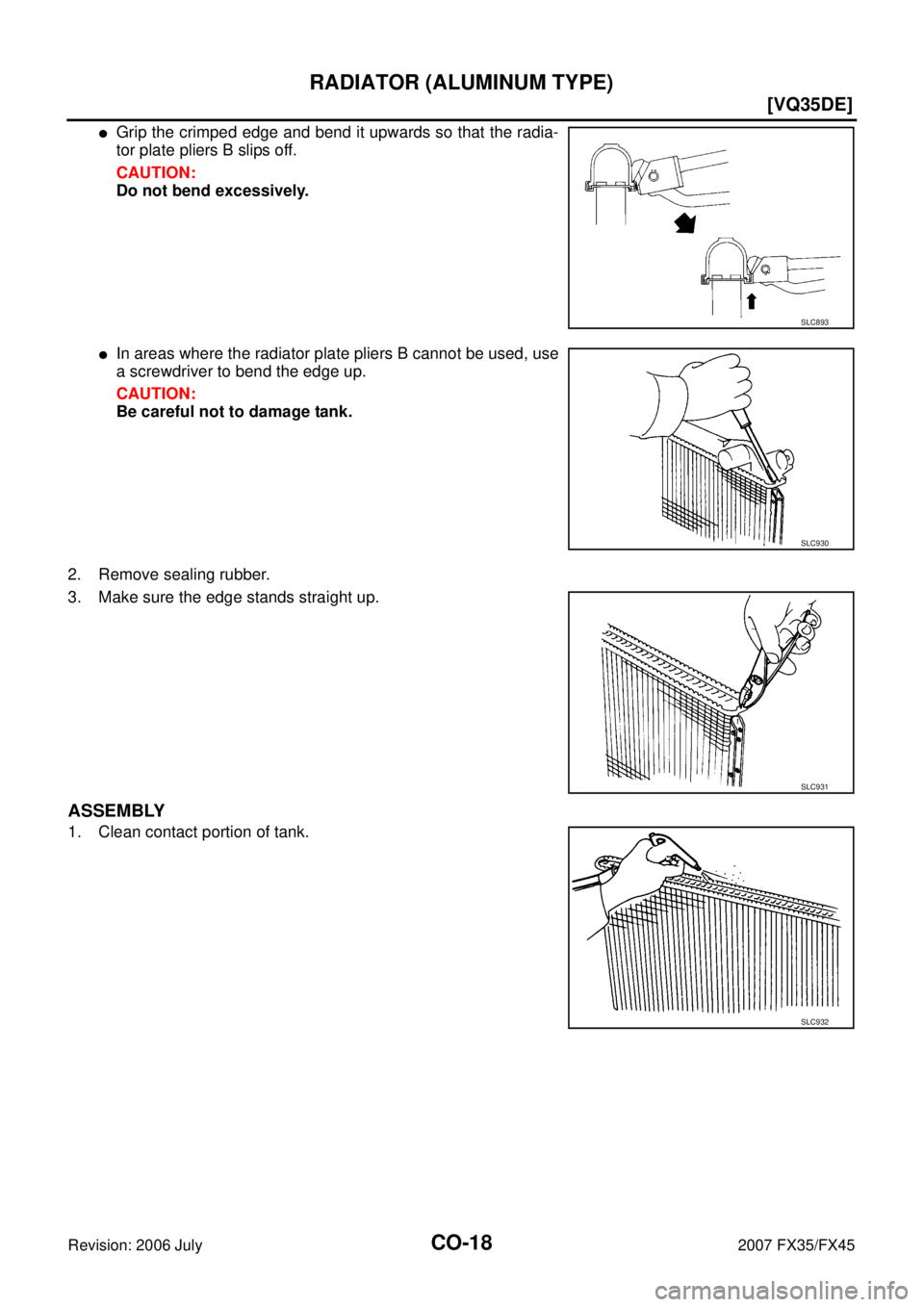
�Grip the crimped edge and bend it upwards so that the radia-
tor plate pliers B slips off.
CAUTION:
Do not bend excessively.
�In areas where the radiator plate pliers B cannot be used, use
a screwdriver to bend the edge up.
CAUTION:
Be careful not to damage tank.
2. Remove sealing rubber.
3. Make sure the edge stands straight up.
ASSEMBLY
1. Clean contact portion of tank.
SLC893
SLC930
SLC931
SLC932
Page 1209 of 4366
RADIATOR (ALUMINUM TYPE) CO-19
[VQ35DE]
C
D E
F
G H
I
J
K L
M A
CO
Revision: 2006 July 2007 FX35/FX45
2. Install new sealing rubber while pushing it with fingers.
CAUTION:
Be careful not to twist sealing rubber.
3. Caulk tank in numerical order as shown in the figure with the radiator plate pliers A (SST).
�Use pliers in the locations where the radiator plate pliers A
cannot be used.
SLC917A
SLC904-A
PBIC2076E
SLC897
Page 1210 of 4366
CO-20
[VQ35DE]
RADIATOR (ALUMINUM TYPE)
Revision: 2006 July 2007 FX35/FX45
4. Make sure that the rim is completely crimped down.
5. Make sure that there is no leakage. Refer to CO-20, "
INSPECTION" .
INSPECTION
1. Apply pressure with the radiator cap tester adapter (SST) and
the radiator cap tester (commercial service tool).
WARNING:
To prevent the risk of hose coming undone while under
pressure, securely fasten it down with hose clamp.
CAUTION:
Attach hose to A/T fluid cooler to seal its inlet and outlet.
2. Check for leakage by soaking radiator in water container with the testing pressure applied. Standard height “H” : 8.0 - 8.4 mm (0.315 - 0.331 in)
SLC554A
Testing pressure
: 157 kPa (1.6 kg/cm
2 , 23 psi)
SLC933-A
SLC934
![INFINITI FX35 2007 Service Manual RADIATOR (ALUMINUM TYPE) CO-17
[VQ35DE]
C
D E
F
G H
I
J
K L
M A
CO
Revision: 2006 July 2007 FX35/FX45
RADIATOR (ALUMINUM TYPE)PFP:21460
ComponentsNBS003K0
Disassembly and AssemblyNBS003K1](/manual-img/42/57018/w960_57018-1206.png "INFINITI FX35 2007 Service Manual RADIATOR (ALUMINUM TYPE) CO-17
[VQ35DE]
C
D E
F
G H
I
J
K L
M A
CO
Revision: 2006 July 2007 FX35/FX45
RADIATOR (ALUMINUM TYPE)PFP:21460
ComponentsNBS003K0
Disassembly and AssemblyNBS003K1")
![INFINITI FX35 2007 Service Manual RADIATOR (ALUMINUM TYPE) CO-19
[VQ35DE]
C
D E
F
G H
I
J
K L
M A
CO
Revision: 2006 July 2007 FX35/FX45
2. Install new sealing rubber while pushing it with fingers.
CAUTION:
Be careful no](/manual-img/42/57018/w960_57018-1208.png "INFINITI FX35 2007 Service Manual RADIATOR (ALUMINUM TYPE) CO-19
[VQ35DE]
C
D E
F
G H
I
J
K L
M A
CO
Revision: 2006 July 2007 FX35/FX45
2. Install new sealing rubber while pushing it with fingers.
CAUTION:
Be careful no")
![INFINITI FX35 2007 Service Manual CO-20
[VQ35DE]
RADIATOR (ALUMINUM TYPE)
Revision: 2006 July 2007 FX35/FX45
4. Make sure that the rim is completely crimped down.
5. Make sure that there is no leakage. Refer to CO-20, "
INSPECTION](/manual-img/42/57018/w960_57018-1209.png "INFINITI FX35 2007 Service Manual CO-20
[VQ35DE]
RADIATOR (ALUMINUM TYPE)
Revision: 2006 July 2007 FX35/FX45
4. Make sure that the rim is completely crimped down.
5. Make sure that there is no leakage. Refer to CO-20, \"
INSPECTION")