Page 3824 of 4366
PG-80
FUSE BLOCK - JUNCTION BOX (J/B)
Revision: 2006 July 2007 FX35/FX45
FUSE BLOCK - JUNCTION BOX (J/B)PFP:24350
Terminal ArrangementNKS003GU
CKIM0652E
Page 3825 of 4366
FUSE, FUSIBLE LINK AND RELAY BOX PG-81
C
D E
F
G H
I
J
L
M A
B
PG
Revision: 2006 July 2007 FX35/FX45
FUSE, FUSIBLE LINK AND RELAY BOXPFP:24382
Terminal ArrangementNKS003GV
CKIM0223E
Page 3826 of 4366
PG-82
FUSE, FUSIBLE LINK AND RELAY BOX
Revision: 2006 July 2007 FX35/FX45
Page 3913 of 4366

SUNROOF RF-11
C
D E
F
G H
J
K L
M A
B
RF
Revision: 2006 July 2007 FX35/FX45
System DescriptionNIS001SY
Power supplied at all time
�through 50A fusible link (letter M , located in the fuse and fusible link box)
�to BCM terminal 55.
�through 15A fuse [No.22, located in the fuse block (J/B)]
�to BCM terminal 42.
�through BCM terminal 54
�to sunroof motor assembly terminal 7.
When ignition switch ON or START position,
Power is supplied
�through 15A fuse [No.1, located in the fuse block (J/B)]
�to BCM terminal 38.
�through BCM terminal 53
�to sunroof motor assembly terminal 9.
Ground is supplied
�to BCM terminal 49 and 52
�through body grounds M35, M45, M85 and R6.
TILT UP / SLIDE CLOSE OPERATION
When tilt up / slide close switch is pressed,
Ground is supplied
�to sunroof motor assembly terminal 1
�through sunroof switch terminal 3
�through sunroof switch terminal 2
�through body grounds M35, M45, M85 and R6.
Then, the sunroof tilt up / slide close.
TILT DOWN / SLIDE OPEN OPERATION
When tilt down / slide open switch is pressed,
Ground is supplied
�to sunroof motor assembly terminal 5
�through sunroof switch terminal 1
�through sunroof switch terminal 2
�through body grounds M35, M45, M85 and R6.
Then, the sunroof tilt down / slide open.
AUTO OPERATION
The power sunroof AUTO feature makes it possible to slide open and slide close or tilt up and tilt down the
sunroof without holding the sunroof switch in the down or up / tilt up or tilt down position.
RETAINED POWER OPERATION
When the ignition switch is turned to OFF position from ON position, power is supplied for 45 seconds.
�through BCM terminal 53.
�to sunroof motor assembly terminal 9.
When power is supplied, the sunroof can be operated.
The retained power operation is canceled when the driver or passenger side door is opened.
RAP signal period can be changed by CONSULT-II. Refer to RF-15, "
CONSULT-II Function (BCM)" .
Page 3918 of 4366

RF-16
SUNROOF
Revision: 2006 July 2007 FX35/FX45
Trouble Diagnosis Chart by SymptomNIS001T6
Check BCM Power Supply and Ground CircuitNIS001T7
1. CHECK FUSE
�Check 15A fuse [No.1, located in the fuse block (J/B)]
�Check 15A fuse [No.22, located in the fuse block (J/B)]
�Check 50A fusible link (letter M, located in the fuse and fusible link box).
NOTE:
Refer to RF-10, "
Component Parts and Harness Connector Location" .
OK or NG
OK >> GO TO 2.
NG >> If fuse is blown out, be sure to eliminate cause of malfunction before installing new fuse. Refer to
RF-10, "
Component Parts and Harness Connector Location" .
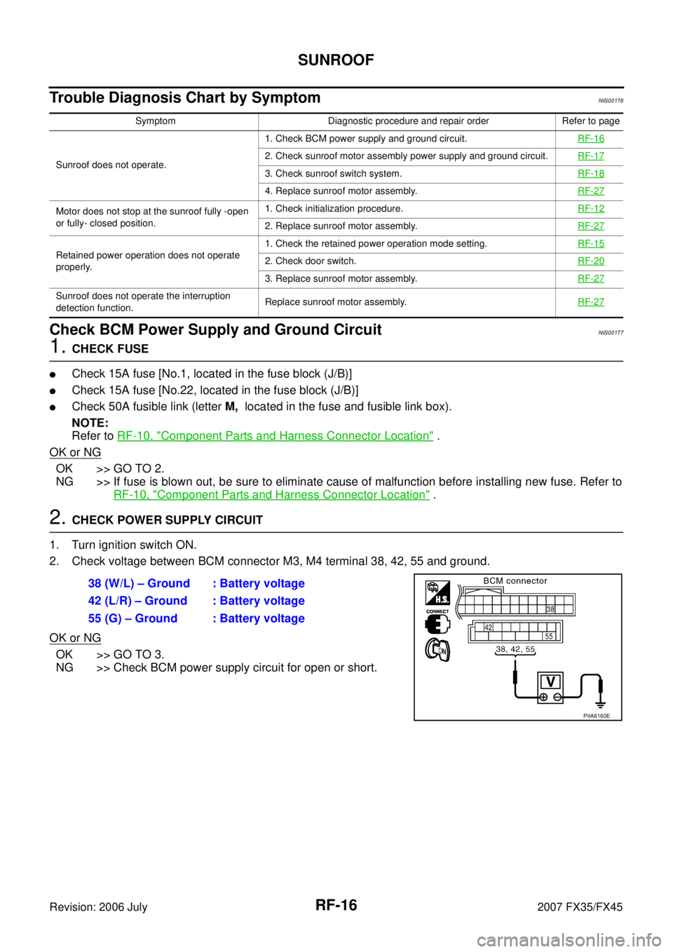
2. CHECK POWER SUPPLY CIRCUIT
1. Turn ignition switch ON.
2. Check voltage between BCM connector M3, M4 terminal 38, 42, 55 and ground.
OK or NG
OK >> GO TO 3.
NG >> Check BCM power supply circuit for open or short.
Symptom Diagnostic procedure and repair order Refer to page
Sunroof does not operate. 1. Check BCM power supply and ground circuit.
RF-16
2. Check sunroof motor assembly power supply and ground circuit.RF-17
3. Check sunroof switch system. RF-18
4. Replace sunroof motor assembly.RF-27
Motor does not stop at the sunroof fully -open
or fully- closed position. 1. Check initialization procedure.
RF-12
2. Replace sunroof motor assembly.RF-27
Retained power operation does not operate
properly. 1. Check the retained power operation mode setting.
RF-152. Check door switch.RF-20
3. Replace sunroof motor assembly.RF-27
Sunroof does not operate the interruption
detection function. Replace sunroof motor assembly.
RF-27
38 (W/L) – Ground : Battery voltage
42 (L/R) – Ground : Battery voltage
55 (G) – Ground : Battery voltage
PIIA6160E
Page 4015 of 4366

STARTING SYSTEM SC-17
C
D E
F
G H
I
J
L
M A
B
SC
Revision: 2006 July 2007 FX35/FX45
DIAGNOSTIC PROCEDURE 2
Check “S” Connector Circuit
1. CHECK POWER SUPPLY FOR STARTER MOTOR “S” TERMINAL
1. Remove fuel pump fuse.
2. Crank or start the engine (where possible) until the fuel pressure is released.
3. Turn ignition switch OFF.
4. Disconnect starter motor connector.
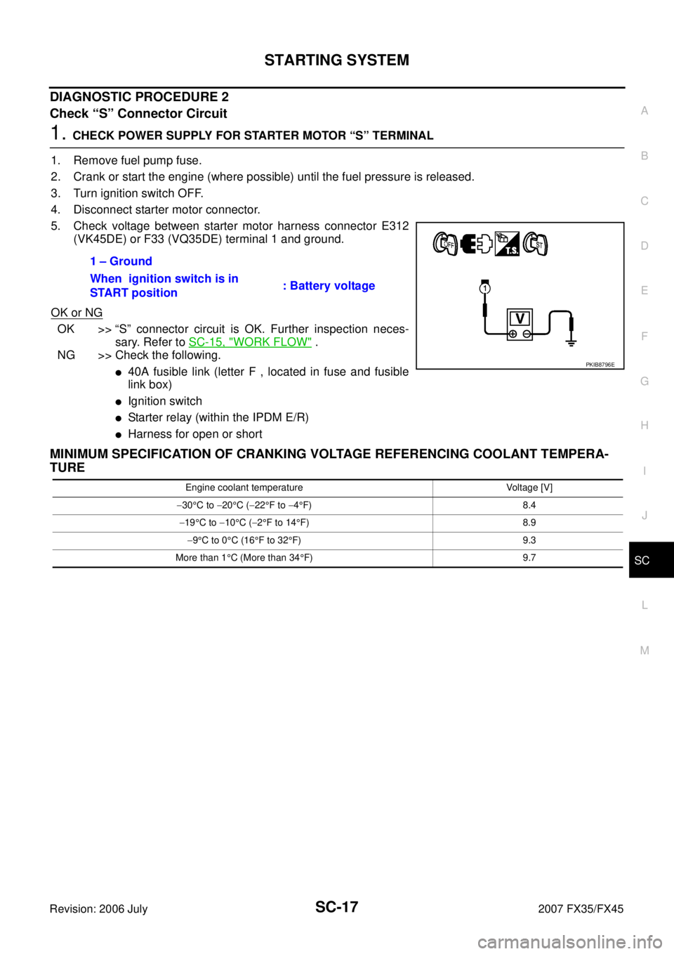
5. Check voltage between starter motor harness connector E312 (VK45DE) or F33 (VQ35DE) terminal 1 and ground.
OK or NG
OK >> “S” connector circuit is OK. Further inspection neces- sary. Refer to SC-15, "
WORK FLOW" .
NG >> Check the following.
�40A fusible link (letter F , located in fuse and fusible
link box)
�Ignition switch
�Starter relay (within the IPDM E/R)
�Harness for open or short
MINIMUM SPECIFICATION OF CRANKING VOLTAGE REFERENCING COOLANT TEMPERA-
TURE
1 – Ground
When ignition switch is in
START position : Battery voltage
PKIB8796E
Engine coolant temperature Voltage [V]
− 30 °C to −20 °C ( −22 °F to −4°F) 8.4
− 19 °C to −10 °C ( −2°F to 14 °F) 8.9
− 9°C to 0 °C (16 °F to 32 °F) 9.3
More than 1 °C (More than 34 °F) 9.7
Page 4075 of 4366

AUTOMATIC DRIVE POSITIONER SE-37
C
D E
F
G H
J
K L
M A
B
SE
Revision: 2006 July 2007 FX35/FX45
CHECK POWER SUPPLY AND GROUND
1. CHECK FUSE
Check if any of the following fuses in the BCM are blown.
�Check 50A fusible link (letter M , located in the fuse and fusible link box.)
�Check 15A fuse [No.22, located in the fuse block (J/B)]
�Check 10A fuse [No.1, located in the fuse block (J/B)]
�Check 10A fuse [No.6, located in the fuse block (J/B)]
NOTE:
Refer to SE-15, "
Component Parts and Harness Connector Location" .
OK or NG
OK >> GO TO 2.
NG >> If fuse is blown out, be sure to eliminate cause of malfunction before installing new fuse. Refer to
SE-15, "
Component Parts and Harness Connector Location" .
2. CHECK POWER SUPPLY CIRCUIT (BCM)
1. Turn ignition switch OFF.
2. Disconnect BCM connector.
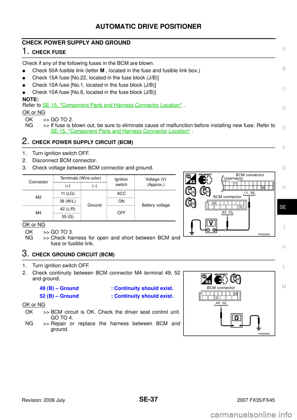
3. Check voltage between BCM connector and ground.
OK or NG
OK >> GO TO 3.
NG >> Check harness for open and short between BCM and fuse or fusible link.
3. CHECK GROUND CIRCUIT (BCM)
1. Turn ignition switch OFF.
2. Check continuity between BCM connector M4 terminal 49, 52 and ground.
OK or NG
OK >> BCM circuit is OK. Check the driver seat control unit. GO TO 4.
NG >> Repair or replace the harness between BCM and ground.
Connector Terminals (Wire color)
Ignition
switch Voltage (V)
(Approx.)
(+) (–)
M3 11 (LG)
Ground ACC
Battery voltage
38 (W/L) ON
M4 42 (L/R)
OFF
55 (G)
PIIA5083E
49 (B) – Ground : Continuity should exist.
52 (B) – Ground : Continuity should exist.
PIIA5084E
Page 4310 of 4366

WW-4
FRONT WIPER AND WASHER SYSTEM
Revision: 2006 July 2007 FX35/FX45
FRONT WIPER AND WASHER SYSTEMPFP:28810
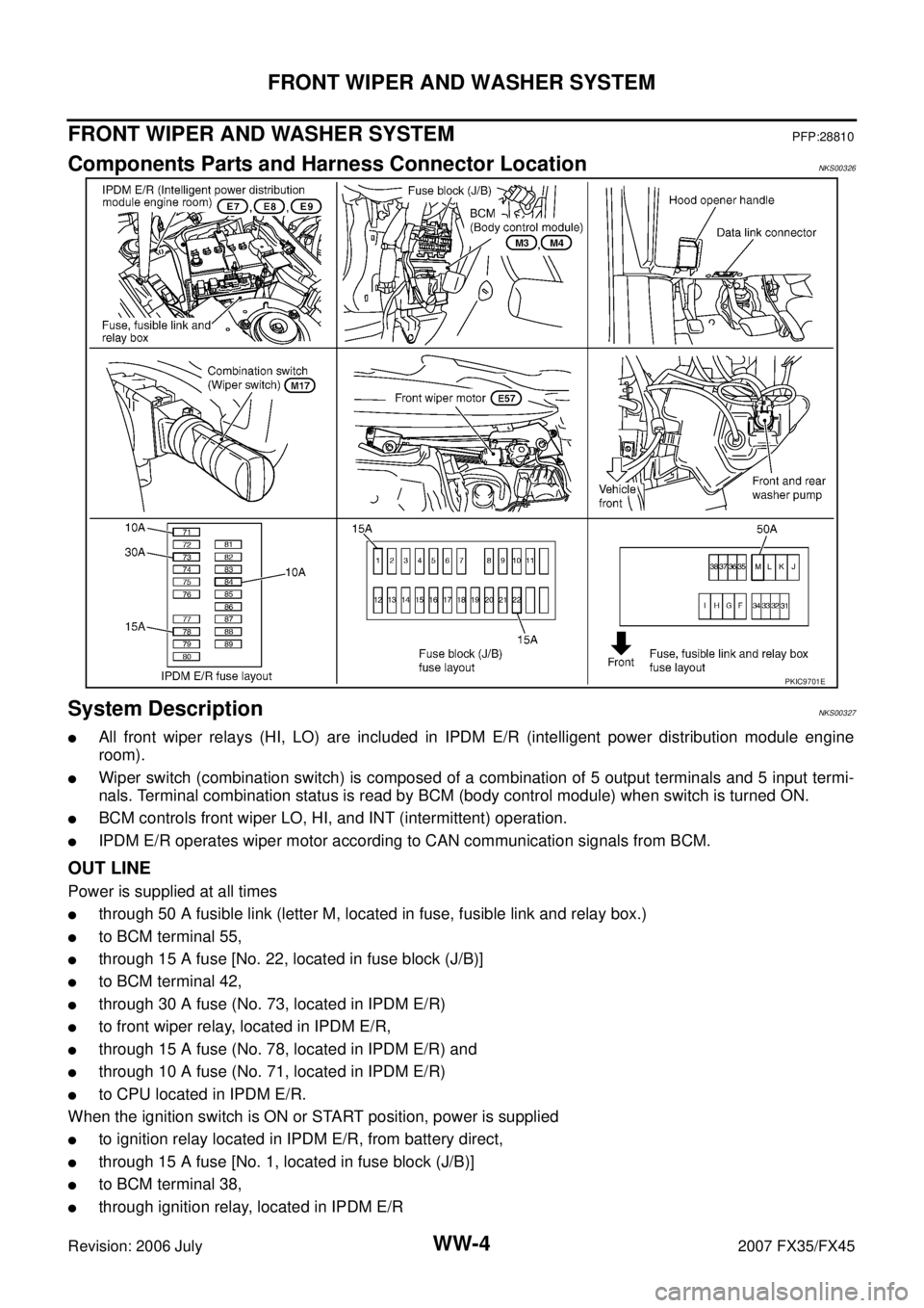
Components Parts and Harness Connector LocationNKS00326
System DescriptionNKS00327
�All front wiper relays (HI, LO) are included in IPDM E/R (intelligent power distribution module engine
room).
�Wiper switch (combination switch) is composed of a combination of 5 output terminals and 5 input termi-
nals. Terminal combination status is read by BCM (body control module) when switch is turned ON.
�BCM controls front wiper LO, HI, and INT (intermittent) operation.
�IPDM E/R operates wiper motor according to CAN communication signals from BCM.
OUT LINE
Power is supplied at all times
�through 50 A fusible link (letter M, located in fuse, fusible link and relay box.)
�to BCM terminal 55,
�through 15 A fuse [No. 22, located in fuse block (J/B)]
�to BCM terminal 42,
�through 30 A fuse (No. 73, located in IPDM E/R)
�to front wiper relay, located in IPDM E/R,
�through 15 A fuse (No. 78, located in IPDM E/R) and
�through 10 A fuse (No. 71, located in IPDM E/R)
�to CPU located in IPDM E/R.
When the ignition switch is ON or START position, power is supplied
�to ignition relay located in IPDM E/R, from battery direct,
�through 15 A fuse [No. 1, located in fuse block (J/B)]
�to BCM terminal 38,
�through ignition relay, located in IPDM E/R
PKIC9701E