Page 1331 of 4366
LANE DEPARTURE WARNING SYSTEM DI-85
C
D E
F
G H
I
J
L
M A
B
DI
Revision: 2006 July 2007 FX35/FX45
7. Touch “NEXT”, then a keyboard window is displayed. And input
“Dh”, and then touch “ENTER”.
NOTE:
Check the value “Dh”. Refer to DI-83, "
VEHICLE HEIGHT
CHECK" .
8. Check the regulated value. (Spec.) NOTE:
Check the value input at step 8.
a. Touch “NEXT” if appropriate.
b. Touch “CHANGE SET” to change “Dh”.
9. Touch “NEXT”. CAUTION:
Never change “Ht”.
10. Touch “NEXT”. CAUTION:
Never change “Dt”.
SKIB3147E
SKIB3148E
SKIB3149E
SKIB3173E
Page 1332 of 4366
DI-86
LANE DEPARTURE WARNING SYSTEM
Revision: 2006 July 2007 FX35/FX45
11. Touch “START”.
12. Check it display item.
a. “NORMALLY COMPLETED” is displayed, then touching “COM- PLETION”.
b. Perform the following services when displayed “SUSPENSION” or “ABNORMALLY COMPLETED”.
NOTE:
Replace camera unit if “suspension” is repeatedly indicated though the above two service is performed.
13. Check if “NORMALLY COMPLETED” is displayed and close the aiming adjustment procedure by touching “END”.
SKIB3150E
SKIB3151E
SKIB3152E
Displays item Service procedure
SUSPENSION 00H Routine not activated
Position the target appropriately again. Perform the aiming again.
Refer to DI-80, "
Camera Aiming Adjustment" .
10H Writing error
ABNORMALLY COMPLETED —
SKIB3153E
Page 1333 of 4366
LANE DEPARTURE WARNING SYSTEM DI-87
C
D E
F
G H
I
J
L
M A
B
DI
Revision: 2006 July 2007 FX35/FX45
Check After The Adjustment
1. Perform the LDW camera unit self-diagnosis. Refer to DI-92, "CONSULT-II Function (LDW)" .
2. Test the LDW system operation by running test. Refer to DI-80, "
LDW SYSTEM RUNNING TEST" .
Component Parts and Harness Connector LocationNKS00316
SKIB8486E
Page 1334 of 4366
DI-88
LANE DEPARTURE WARNING SYSTEM
Revision: 2006 July 2007 FX35/FX45
SchematicNKS00317
TKWM4366E
Page 1335 of 4366
LANE DEPARTURE WARNING SYSTEM DI-89
C
D E
F
G H
I
J
L
M A
B
DI
Revision: 2006 July 2007 FX35/FX45
Wiring Diagram — LDW —NKS00318
TKWM4367E
Page 1336 of 4366
DI-90
LANE DEPARTURE WARNING SYSTEM
Revision: 2006 July 2007 FX35/FX45
TKWM4368E
Page 1337 of 4366
LANE DEPARTURE WARNING SYSTEM DI-91
C
D E
F
G H
I
J
L
M A
B
DI
Revision: 2006 July 2007 FX35/FX45
TKWM4369E
Page 1338 of 4366

DI-92
LANE DEPARTURE WARNING SYSTEM
Revision: 2006 July 2007 FX35/FX45
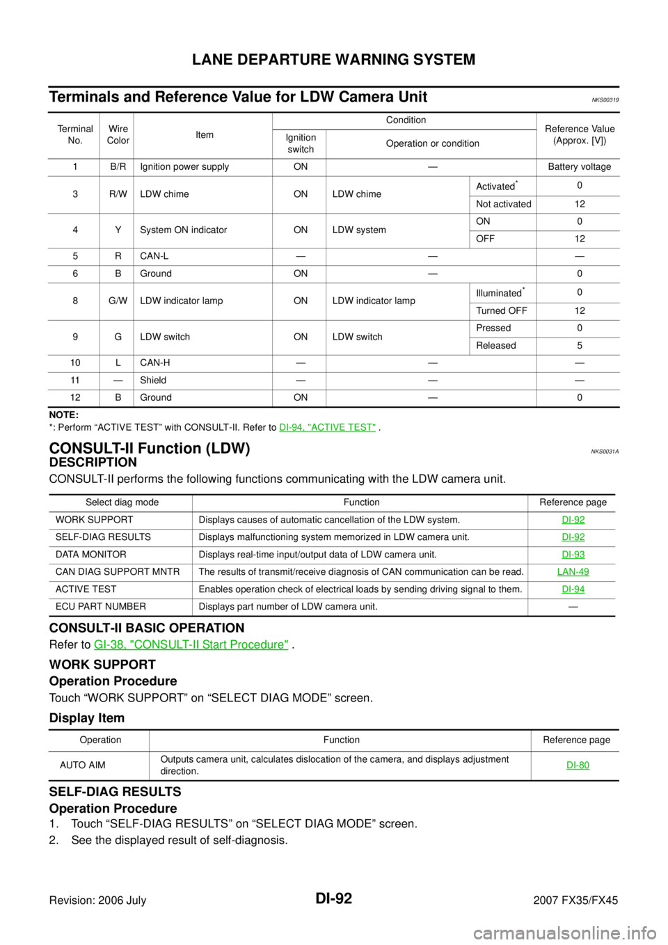
Terminals and Reference Value for LDW Camera UnitNKS00319
NOTE:
*: Perform “ACTIVE TEST” with CONSULT-II. Refer to DI-94, "
ACTIVE TEST" .
CONSULT-II Function (LDW)NKS0031A
DESCRIPTION
CONSULT-II performs the following functions communicating with the LDW camera unit.
CONSULT-II BASIC OPERATION
Refer to GI-38, "CONSULT-II Start Procedure" .
WORK SUPPORT
Operation Procedure
Touch “WORK SUPPORT” on “SELECT DIAG MODE” screen.
Display Item
SELF-DIAG RESULTS
Operation Procedure
1. Touch “SELF-DIAG RESULTS” on “SELECT DIAG MODE” screen.
2. See the displayed result of self-diagnosis.
Te r m i n a l No. Wire
Color Item Condition
Reference Value
(Approx. [V])
Ignition
switch Operation or condition
1 B/R Ignition power supply ON — Battery voltage
3 R/W LDW chime ON LDW chime Activated
*0
Not activated 12
4 Y System ON indicator ON LDW system ON 0
OFF 12
5 R CAN-L — — —
6 B Ground ON — 0
8 G/W LDW indicator lamp ON LDW indicator lamp Illuminated
*0
Turned OFF 12
9 G LDW switch ON LDW switch Pressed 0
Released 5
10 L CAN-H — — — 11 — Shield — — —
12 B Ground ON — 0
Select diag mode Function Reference page
WORK SUPPORT Displays causes of automatic cancellation of the LDW system. DI-92
SELF-DIAG RESULTS Displays malfunctioning system memorized in LDW camera unit.DI-92
DATA MONITOR Displays real-time input/output data of LDW camera unit.DI-93
CAN DIAG SUPPORT MNTR The results of transmit/receive diagnosis of CAN communication can be read.LAN-49
ACTIVE TEST Enables operation check of electrical loads by sending driving signal to them. DI-94
ECU PART NUMBER Displays part number of LDW camera unit. —
Operation Function Reference page
AUTO AIM Outputs camera unit, calculates dislocation of the camera, and displays adjustment
direction.
DI-80