Page 1295 of 4366

WARNING LAMPS DI-49
C
D E
F
G H
I
J
L
M A
B
DI
Revision: 2006 July 2007 FX35/FX45
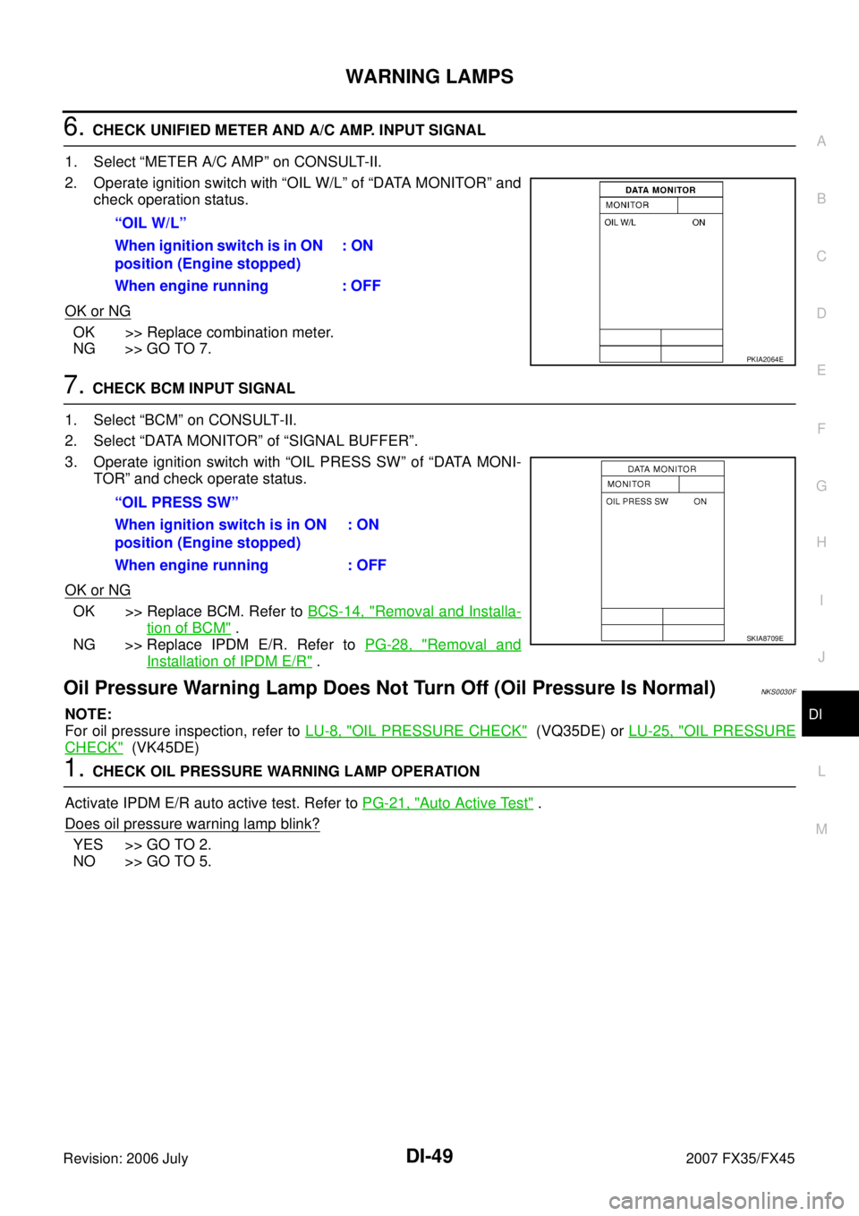
6. CHECK UNIFIED METER AND A/C AMP. INPUT SIGNAL
1. Select “METER A/C AMP” on CONSULT-II.
2. Operate ignition switch with “OIL W/L” of “DATA MONITOR” and check operation status.
OK or NG
OK >> Replace combination meter.
NG >> GO TO 7.
7. CHECK BCM INPUT SIGNAL
1. Select “BCM” on CONSULT-II.
2. Select “DATA MONITOR” of “SIGNAL BUFFER”.
3. Operate ignition switch with “OIL PRESS SW” of “DATA MONI- TOR” and check operate status.
OK or NG
OK >> Replace BCM. Refer to BCS-14, "Removal and Installa-
tion of BCM" .
NG >> Replace IPDM E/R. Refer to PG-28, "
Removal and
Installation of IPDM E/R" .
Oil Pressure Warning Lamp Does Not Turn Off (Oil Pressure Is Normal)NKS0030F
NOTE:
For oil pressure inspection, refer to LU-8, "
OIL PRESSURE CHECK" (VQ35DE) or LU-25, "OIL PRESSURE
CHECK" (VK45DE)
1. CHECK OIL PRESSURE WARNING LAMP OPERATION
Activate IPDM E/R auto active test. Refer to PG-21, "
Auto Active Test" .
Does oil pressure warning lamp blink?
YES >> GO TO 2.
NO >> GO TO 5. “OIL W/L”
When ignition switch is in ON
position (Engine stopped) : ON
When engine running : OFF
PKIA2064E
“OIL PRESS SW”
When ignition switch is in ON
position (Engine stopped) : ON
When engine running : OFF
SKIA8709E
Page 1296 of 4366

DI-50
WARNING LAMPS
Revision: 2006 July 2007 FX35/FX45
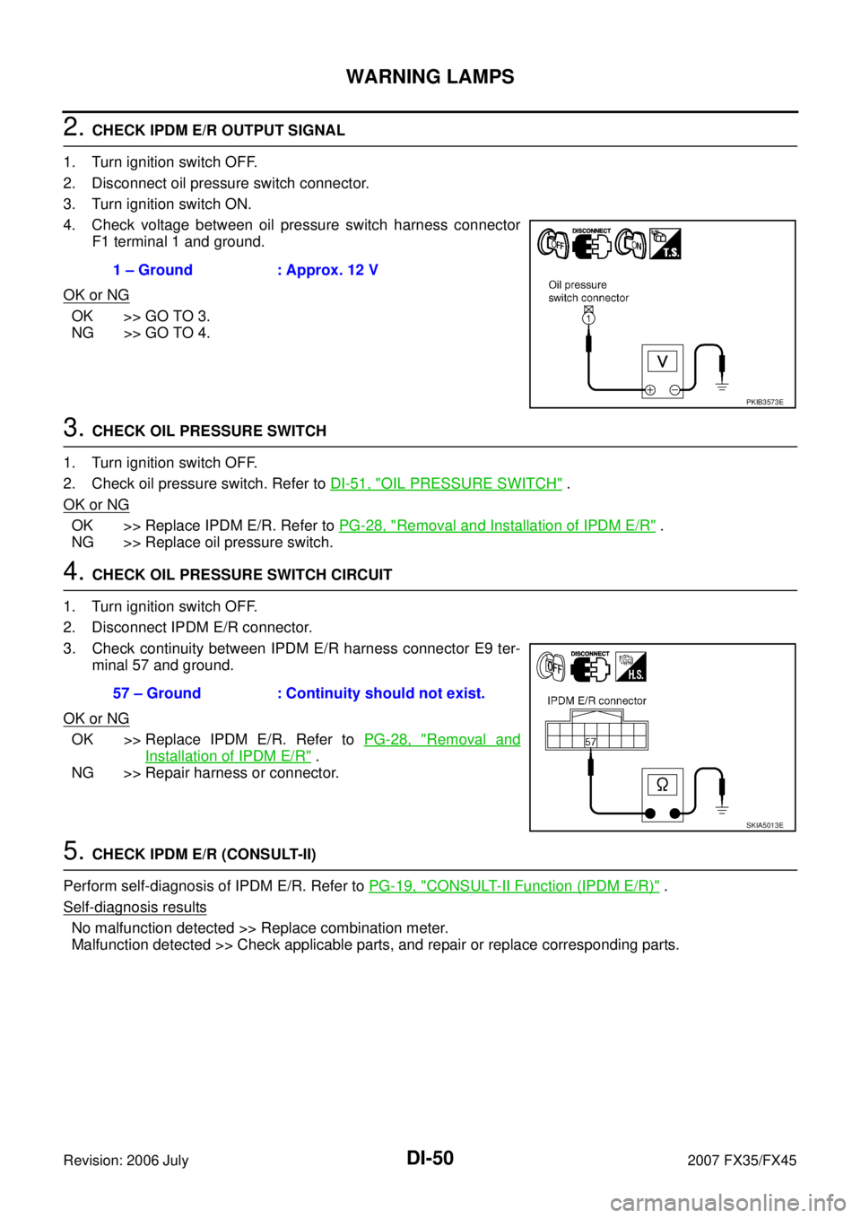
2. CHECK IPDM E/R OUTPUT SIGNAL
1. Turn ignition switch OFF.
2. Disconnect oil pressure switch connector.
3. Turn ignition switch ON.
4. Check voltage between oil pressure switch harness connector F1 terminal 1 and ground.
OK or NG
OK >> GO TO 3.
NG >> GO TO 4.
3. CHECK OIL PRESSURE SWITCH
1. Turn ignition switch OFF.
2. Check oil pressure switch. Refer to DI-51, "
OIL PRESSURE SWITCH" .
OK or NG
OK >> Replace IPDM E/R. Refer to PG-28, "Removal and Installation of IPDM E/R" .
NG >> Replace oil pressure switch.
4. CHECK OIL PRESSURE SWITCH CIRCUIT
1. Turn ignition switch OFF.
2. Disconnect IPDM E/R connector.
3. Check continuity between IPDM E/R harness connector E9 ter- minal 57 and ground.
OK or NG
OK >> Replace IPDM E/R. Refer to PG-28, "Removal and
Installation of IPDM E/R" .
NG >> Repair harness or connector.
5. CHECK IPDM E/R (CONSULT-II)
Perform self-diagnosis of IPDM E/R. Refer to PG-19, "
CONSULT-II Function (IPDM E/R)" .
Self-diagnosis results
No malfunction detected >> Replace combination meter.
Malfunction detected >> Check applicable parts, and repair or replace corresponding parts. 1 – Ground : Approx. 12 V
PKIB3573E
57 – Ground : Continuity should not exist.
SKIA5013E
Page 1297 of 4366
WARNING LAMPS DI-51
C
D E
F
G H
I
J
L
M A
B
DI
Revision: 2006 July 2007 FX35/FX45
Component InspectionNKS0030G
OIL PRESSURE SWITCH
Check continuity between oil pressure switch and ground.
Condition
Oil pressure [kPa (kg/cm2 , psi)] Continuity
Engine stopped Less than 29 (0.3, 4) Yes Engine running More than 29 (0.3, 4) No
ELF0044D
Page 1302 of 4366

DI-56
WARNING CHIME
Revision: 2006 July 2007 FX35/FX45
WARNING CHIMEPFP:24814
System DescriptionNKS0030J
�Buzzer for warning chime system is installed in the combination meter.
�The buzzer sounds when the combination meter receives buzzer output signal from each unit through uni-
fied meter and A/C amp.
POWER SUPPLY AND CIRCUIT
Power is supplied at all times
�through 50A fusible link (letter M , located in the fuse and fusible link block)
�to BCM terminal 55,
�through 15A fuse [No. 22, located in the fuse block (J/B)]
�to key switch and ignition knob switch terminal 3 (with Intelligent Key)
�to key switch terminal 2 (without Intelligent Key), and
�to BCM terminal 42,
�through 10A fuse [No. 38, located in the fuse and fusible link block (with Intelligent Key)]
�to key switch and ignition knob switch terminal 1,
�through 10A fuse [No. 19, located in the fuse block (J/B)]
�to unified meter and A/C amp. terminal 21, and
�to combination meter terminal 8.
When ignition switch is in ON or START position, power is supplied
�through 15A fuse [No. 1, located in the fuse block (J/B)]
�to BCM terminal 38,
�through 10A fuse [No. 12, located in the fuse block (J/B)]
�to unified meter and A/C amp. terminal 22,
�through 10A fuse [No. 14, located in the fuse block (J/B)]
�to combination meter terminal 7.
Ground is supplied
�to BCM terminals 49 and 52,
�to unified meter and A/C amp. terminals 29 and 30, and
�to combination meter terminals 5, 6 and 15
�through grounds M35, M45 and M85.
Page 1303 of 4366

WARNING CHIME DI-57
C
D E
F
G H
I
J
L
M A
B
DI
Revision: 2006 July 2007 FX35/FX45
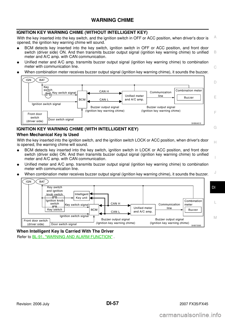
IGNITION KEY WARNING CHIME (WITHOUT INTELLIGENT KEY)
With the key inserted into the key switch, and the ignition switch in OFF or ACC position, when driver's door is
opened, the ignition key warning chime will sound.
�BCM detects key inserted into the key switch, ignition switch in OFF or ACC position, and front door
switch (driver side) ON. And then transmits buzzer output signal (ignition key warning chime) to unified
meter and A/C amp. with CAN communication.
�Unified meter and A/C amp. transmits buzzer output signal (ignition key warning chime) to combination
meter with communication line.
�When combination meter receives buzzer output signal (ignition key warning chime), it sounds the buzzer.
IGNITION KEY WARNING CHIME (WITH INTELLIGENT KEY)
When Mechanical Key Is Used
With the key inserted into the ignition switch, and the ignition switch LOCK or ACC position, when driver's door
is opened, the warning chime will sound.
�BCM detects key inserted into the key switch, ignition switch in LOCK or ACC position, and front door
switch (driver side) ON. And then transmits buzzer output signal (ignition key warning chime) to unified
meter and A/C amp. with CAN communication.
�Unified meter and A/C amp. transmits buzzer output signal (ignition key warning chime) to combination
meter with communication line.
�When combination meter receives buzzer output signal (ignition key warning chime), it sounds the buzzer.
When Intelligent Key Is Carried With The Driver
Refer to BL-91, "WARNING AND ALARM FUNCTION" .
SKIB6481E
SKIB7258E
Page 1304 of 4366

DI-58
WARNING CHIME
Revision: 2006 July 2007 FX35/FX45
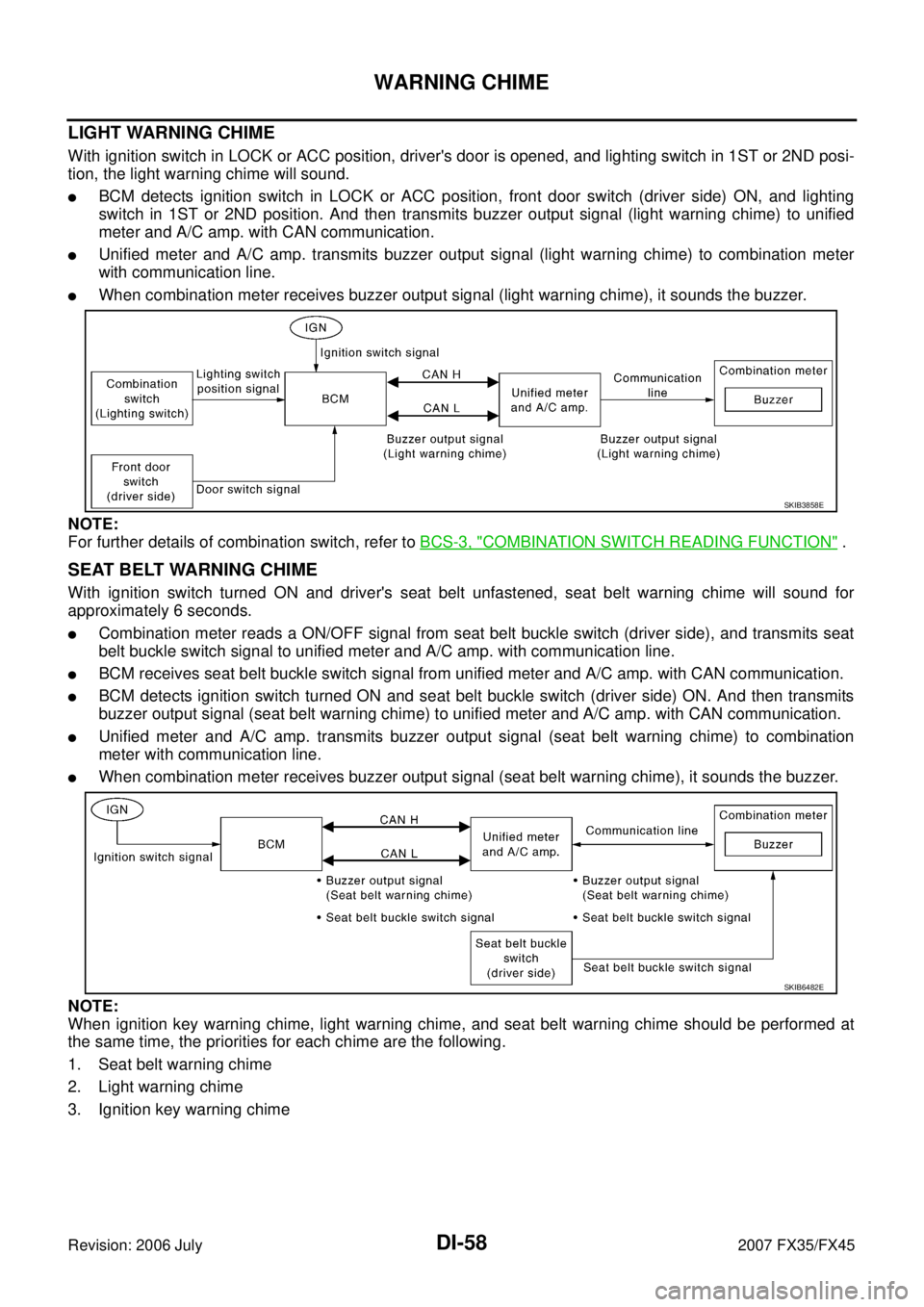
LIGHT WARNING CHIME
With ignition switch in LOCK or ACC position, driver's door is opened, and lighting switch in 1ST or 2ND posi-
tion, the light warning chime will sound.
�BCM detects ignition switch in LOCK or ACC position, front door switch (driver side) ON, and lighting
switch in 1ST or 2ND position. And then transmits buzzer output signal (light warning chime) to unified
meter and A/C amp. with CAN communication.
�Unified meter and A/C amp. transmits buzzer output signal (light warning chime) to combination meter
with communication line.
�When combination meter receives buzzer output signal (light warning chime), it sounds the buzzer.
NOTE:
For further details of combination switch, refer to BCS-3, "
COMBINATION SWITCH READING FUNCTION" .
SEAT BELT WARNING CHIME
With ignition switch turned ON and driver's seat belt unfastened, seat belt warning chime will sound for
approximately 6 seconds.
�Combination meter reads a ON/OFF signal from seat belt buckle switch (driver side), and transmits seat
belt buckle switch signal to unified meter and A/C amp. with communication line.
�BCM receives seat belt buckle switch signal from unified meter and A/C amp. with CAN communication.
�BCM detects ignition switch turned ON and seat belt buckle switch (driver side) ON. And then transmits
buzzer output signal (seat belt warning chime) to unified meter and A/C amp. with CAN communication.
�Unified meter and A/C amp. transmits buzzer output signal (seat belt warning chime) to combination
meter with communication line.
�When combination meter receives buzzer output signal (seat belt warning chime), it sounds the buzzer.
NOTE:
When ignition key warning chime, light warning chime, and seat belt warning chime should be performed at
the same time, the priorities for each chime are the following.
1. Seat belt warning chime
2. Light warning chime
3. Ignition key warning chime
SKIB3858E
SKIB6482E
Page 1305 of 4366
WARNING CHIME DI-59
C
D E
F
G H
I
J
L
M A
B
DI
Revision: 2006 July 2007 FX35/FX45
Component Parts and Harness Connector LocationNKS0030M
SKIB8485E
Page 1306 of 4366
DI-60
WARNING CHIME
Revision: 2006 July 2007 FX35/FX45
SchematicNKS0030N
TKWM4356E