Page 3944 of 4366
RFD-14
SIDE OIL SEAL
Revision: 2006 July 2007 FX35/FX45
SIDE OIL SEALPFP:33142
Removal and InstallationNDS000BP
REMOVAL
1. Remove center muffler with a power tool. Refer to EX-3, "EXHAUST SYSTEM" .
2. Remove rear wheel sensor. Refer to BRC-57, "
WHEEL SENSORS" .
3. Remove drive shaft from final drive. Then suspend it by wire etc. Refer to RAX-9, "
REAR DRIVE SHAFT"
.
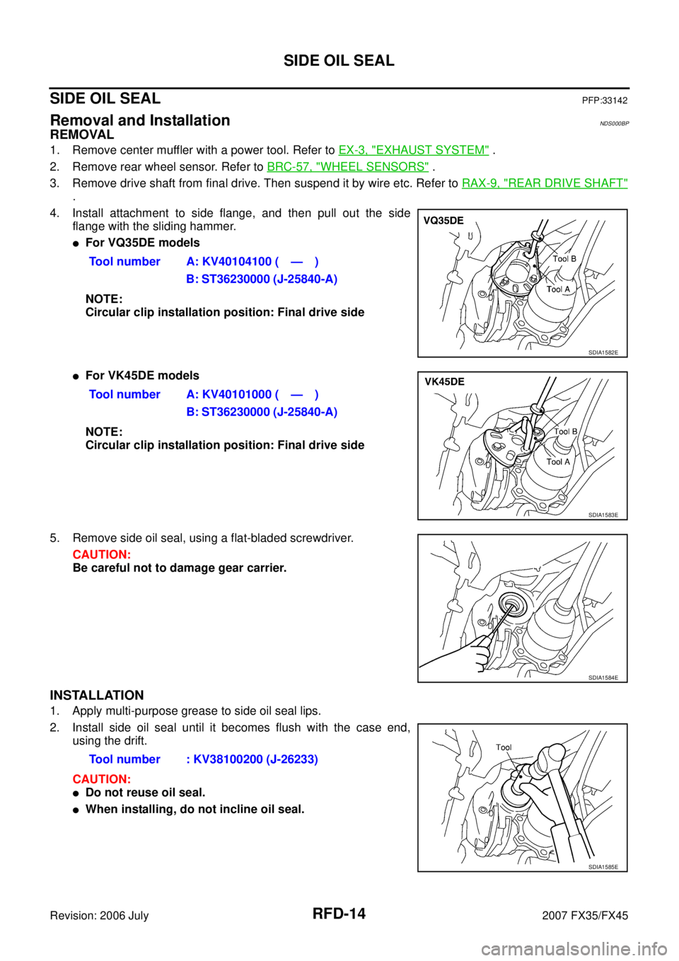
4. Install attachment to side flange, and then pull out the side flange with the sliding hammer.
�For VQ35DE models
NOTE:
Circular clip installation position: Final drive side
�For VK45DE models
NOTE:
Circular clip installation position: Final drive side
5. Remove side oil seal, using a flat-bladed screwdriver. CAUTION:
Be careful not to damage gear carrier.
INSTALLATION
1. Apply multi-purpose grease to side oil seal lips.
2. Install side oil seal until it becomes flush with the case end, using the drift.
CAUTION:
�Do not reuse oil seal.
�When installing, do not incline oil seal. Tool number A: KV40104100 ( — )
B: ST36230000 (J-25840-A)
SDIA1582E
Tool number A: KV40101000 ( — )B: ST36230000 (J-25840-A)
SDIA1583E
SDIA1584E
Tool number : KV38100200 (J-26233)
SDIA1585E
Page 3945 of 4366
SIDE OIL SEAL RFD-15
C E F
G H
I
J
K L
M A
B
RFD
Revision: 2006 July 2007 FX35/FX45
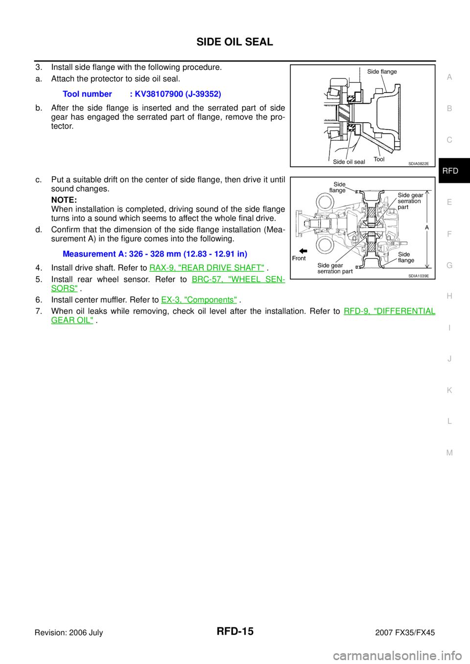
3. Install side flange with the following procedure.
a. Attach the protector to side oil seal.
b. After the side flange is inserted and the serrated part of side gear has engaged the serrated part of flange, remove the pro-
tector.
c. Put a suitable drift on the center of side flange, then drive it until sound changes.
NOTE:
When installation is completed, driving sound of the side flange
turns into a sound which seems to affect the whole final drive.
d. Confirm that the dimension of the side flange installation (Mea- surement A) in the figure comes into the following.
4. Install drive shaft. Refer to RAX-9, "
REAR DRIVE SHAFT" .
5. Install rear wheel sensor. Refer to BRC-57, "
WHEEL SEN-
SORS" .
6. Install center muffler. Refer to EX-3, "
Components" .
7. When oil leaks while removing, check oil level after the installation. Refer to RFD-9, "
DIFFERENTIAL
GEAR OIL" .
Tool number : KV38107900 (J-39352)
SDIA0822E
Measurement A: 326 - 328 mm (12.83 - 12.91 in)
SDIA1039E
Page 3946 of 4366
RFD-16
REAR FINAL DRIVE ASSEMBLY
Revision: 2006 July 2007 FX35/FX45
REAR FINAL DRIVE ASSEMBLYPFP:38300
Removal and InstallationNDS000CW
COMPONENTS
REMOVAL
1. Remove center muffler with a power tool. Refer to EX-3, "EXHAUST SYSTEM" .
2. Remove rear stabilizer bar with a power tool. Refer to RSU-16, "
STABILIZER BAR" .
3. Remove propeller shaft from the final drive. Refer to PR-9, "
Removal and Installation" .
4. Remove drive shaft from final drive with a power tool. Then sus- pend it by wire etc. Refer to RAX-9, "
REAR DRIVE SHAFT" .
5. Remove breather hose from the final drive.
6. Remove rear wheel sensor. Refer to BRC-57, "
WHEEL SEN-
SORS" .
1. Rear final drive assembly 2. Upper stopper 3. Propeller shaft
4. Washer 5. Lower stopper 6. Drive shaft
: For VQ35DE models
: For VK45DE models
Refer to GI-11, "
Components" , for the symbols in the figure.
SDIA3563E
SDIA1094E
Page 3948 of 4366

RFD-18
REAR FINAL DRIVE ASSEMBLY
Revision: 2006 July 2007 FX35/FX45
Disassembly and AssemblyNDS000CX
COMPONENTS
1. Drive pinion lock nut 2. Companion flange 3. Front oil seal
4. Pinion front bearing 5. Gear carrier 6. Side oil seal
7. Side flange 8. Collapsible spacer 9. Pinion rear bearing
10. Pinion height adjusting washer 11. Drive pinion 12. Side bearing adjusting washer
13. Side bearing 14. Side gear thrust washer 15. Circular clip
16. Side gear 17. Lock pin 18. Pinion mate gear
19. Pinion mate thrust washer 20. Pinion mate shaft 21. Drive gear
22. Differential case 23. Bearing cap 24. Filler plug
25. Gasket 26. Rear cover 27. Drain plug
A: Oil seal lip
B: Screw hole
C: After tightening the bolts to the specified torque, tighten the bolts additionally by turning the bolts 31 to 36 degrees.
Refer to GI-11, "
Components" and the followings for the symbols in the figure.
: Apply multi-purpose grease.
: Apply gear oil.
: Apply anti-corrosion oil.
: Apply Genuine Silicone RTV or equivalent. Refer to
GI-48, "
Recommended Chemical Products and Sealants" .
: Apply Genuine High Strength Thread Locking Sealant or equivalent. Refer to
GI-48, "
Recommended Chemical Prod-
ucts and Sealants" .
PDIA0986E
Page 3954 of 4366
RFD-24
REAR FINAL DRIVE ASSEMBLY
Revision: 2006 July 2007 FX35/FX45
10. For proper reinstallation, paint matching marks on one differen-
tial case assembly.
CAUTION:
For matching marks, use paint. Do not damage differential
case and drive gear.
11. Remove drive gear mounting bolts.
12. Tap drive gear off differential case assembly with a soft hammer. CAUTION:
Tap evenly all around to keep drive gear from bending.
13. Remove lock pin of pinion mate shaft with a punch from drive gear side.
14. Remove pinion mate shaft.
15. Turn pinion mate gear, then remove pinion mate gear, pinion mate thrust washer, side gear and side gear thrust washer from
differential case.
Drive Pinion Assembly
1. Remove differential assembly. Refer to RFD-33, "Differential Assembly" .
PDIA0496E
PDIA0759J
SDIA0031J
SDIA0032J
Page 3964 of 4366
RFD-34
REAR FINAL DRIVE ASSEMBLY
Revision: 2006 July 2007 FX35/FX45
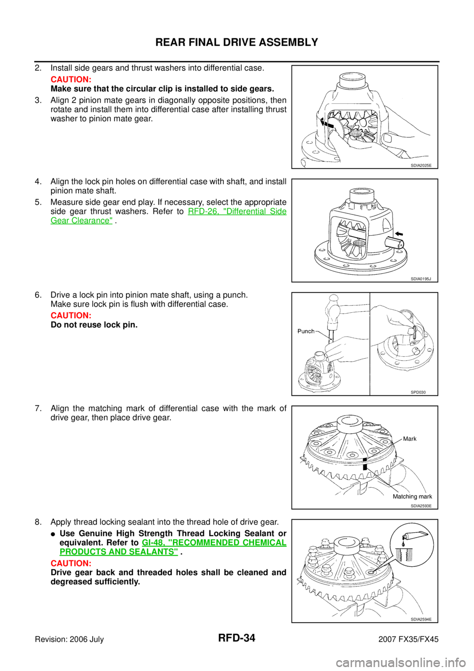
2. Install side gears and thrust washers into differential case.
CAUTION:
Make sure that the circular clip is installed to side gears.
3. Align 2 pinion mate gears in diagonally opposite positions, then rotate and install them into differential case after installing thrust
washer to pinion mate gear.
4. Align the lock pin holes on differential case with shaft, and install pinion mate shaft.
5. Measure side gear end play. If necessary, select the appropriate side gear thrust washers. Refer to RFD-26, "
Differential Side
Gear Clearance" .
6. Drive a lock pin into pinion mate shaft, using a punch. Make sure lock pin is flush with differential case.
CAUTION:
Do not reuse lock pin.
7. Align the matching mark of differential case with the mark of drive gear, then place drive gear.
8. Apply thread locking sealant into the thread hole of drive gear.
�Use Genuine High Strength Thread Locking Sealant or
equivalent. Refer to GI-48, "
RECOMMENDED CHEMICAL
PRODUCTS AND SEALANTS" .
CAUTION:
Drive gear back and threaded holes shall be cleaned and
degreased sufficiently.
SDIA2025E
SDIA0195J
SPD030
SDIA2593E
SDIA2594E
Page 3972 of 4366
RSU-4
NOISE, VIBRATION AND HARSHNESS (NVH) TROUBLESHOOTING
Revision: 2006 July 2007 FX35/FX45
NOISE, VIBRATION AND HARSHNESS (NVH) TROUBLESHOOTINGPFP:00003
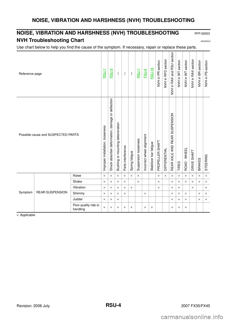
NVH Troubleshooting ChartNES000G3
Use chart below to help you find the cause of the symptom. If necessary, repair or replace these parts.
×: Applicable Reference page
RSU-7RSU-9—
—
—
RSU-7FSU-6RSU-16
NVH in PR section
NVH in RFD section
NVH in RAX and RSU section NVH in WT section
NVH in WT section
NVH in RAX section NVH in BR sectionNVH in PS section
Possible cause and SUSPECTED PARTS
Improper installation, looseness
Shock absorber deformation, damage or deflection
Bushing or mounting deterioration
Parts interference
Spring fatigue
Suspension looseness
Incorrect wheel alignment
Stabilizer bar fatigue
PROPELLER SHAFT
DIFFERENTIAL
REAR AXLE AND REAR SUSPENSION
TIRES
ROAD WHEEL
DRIVE SHAFT
BRAKES
STEERING
Symptom REAR SUSPENSION Noise
×××××× ××××××××
Shake ×××× × × ××××××
Vibration ××××× × ×× × ×
Shimmy ×××× × ××× ××
Judder ××× ××× ××
Poor quality ride or
handling ××××× ×× ×××
Page 3976 of 4366
RSU-8
REAR SUSPENSION ASSEMBLY
Revision: 2006 July 2007 FX35/FX45
REMOVAL
1. Remove tires from vehicle with power tool.
2. Remove brake caliper with power tool. Hang it in a place where it will not interfere with work. Refer to BR-
25, "REAR DISC BRAKE" .
NOTE:
Avoid depressing brake pedal while brake caliper is removed.
3. Remove wheel sensor from rear final drive, then remove wheel sensor harness from rear suspension member.
4. Remove height sensor harness from rear suspension member (if equipped).
5. Remove center muffler and main muffler. Refer to EX-3, "
Components" .
6. Remove stabilizer bar. Refer to RSU-16, "
Removal and Installation" .
7. Remove rear propeller shaft. Refer to PR-9, "
Removal and Installation" .
8. Separate attachments between parking brake cable and vehicle and rear suspension member.
9. Remove rear lower link and coil spring. Refer to RSU-14, "
Removal and Installation" .
10. Remove fixing bolt in lower side of shock absorber with power tool.
11. Set jack under rear final drive.
12. Remove fixing bolts and nuts of tunnel stay and member stay with power tool, then remove those parts from vehicle.
13. Remove fixing bolts and nuts of rear pin stay with power tool and then remove rear pin stay from vehicle.
14. Gradually lowering jack, remove rear suspension assembly.
INSTALLATION
�Refer to RSU-7, "Removal and installation" for tightening torque. Install in the reverse order of removal.
NOTE:
Refer to component parts location and do not reuse non-reusable parts.
�Perform final tightening of installation position of links (rubber bushing) under unladen conditions with tires
on level ground. Check wheel alignment. Refer to RSU-5, "
Wheel Alignment Inspection" .
�After adjusting wheel alignment, adjust neutral position of steering angle sensor. Refer to BRC-6, "Adjust-
ment of Steering Angle Sensor Neutral Position" .
1. Bushing 2. Mounting seal 3. Mounting seal bracket
4. Distance tube 5. Bound bumper cover 6. Bound bumper
7. Shock absorber 8. Upper seat 9. Coil spring
10. Rubber seat 11. Rear lower link 12. Axle assembly
13. Cotter pin 14. Radius rod 15. Front lower link protector
16. Front lower link 17. Stopper rubber 18. Shock absorber assembly
19. Suspension arm 20. Stabilizer connecting rod mounting bracket 21. Stabilizer connecting rod
22. Rear pin stay 23. Rear suspension member 24. Stabilizer bar
25. Stabilizer bushing 26. Stabilizer clamp 27. Member stay
28. Tunnel stay A: With height sensor B: Without height sensor
Refer to GI-11, "
Components" , for the symbols in the figure.