Page 4250 of 4366
TF-46
TRANSFER ASSEMBLY
Revision: 2006 July 2007 FX35/FX45
DISASSEMBLY
Front Case and Rear Case
1. Remove drain plug and filler plug.
2. Remove mainshaft oil seal from front case, using a flat-bladed screwdriver.
CAUTION:
Be careful not to damage the front case and mainshaft.
3. Remove front oil seal from front case, using a flat-bladed screw- driver.
CAUTION:
Be careful not to damage the front case and front drive
shaft.
4. Remove self-lock nut.
5. Put a matching mark on the end of mainshaft. The mark should be in line with the mark on the companion flange.
CAUTION:
For matching mark, use paint. Do not damage mainshaft.
6. Remove companion flange, using a puller. CAUTION:
Be careful not to damage the companion flange.
PDIA0253E
PDIA0255E
SDIA2378E
PDIA0258E
Page 4252 of 4366
TF-48
TRANSFER ASSEMBLY
Revision: 2006 July 2007 FX35/FX45
11. Remove snap ring from front case.
12. Remove mainshaft bearing from front case, using a drift.
13. Remove drive chain and front drive shaft while tapping front drive shaft with plastic hammer.
CAUTION:
Be careful not to tap drive chain.
14. Remove oil gutter from rear case.
15. Remove oil cover bolt and sensor fixing bolt from rear case. And then, remove oil cover.
PDIA0267E
Tool number : KV38100300 (J-25523)
PDIA0256E
PDIA0257E
PDIA0261E
SDIA2403E
Page 4254 of 4366
TF-50
TRANSFER ASSEMBLY
Revision: 2006 July 2007 FX35/FX45
Mainshaft Assembly
1. Separate front case and rear case, then remove mainshaft assembly. Refer to TF-46, "Front Case and
Rear Case" .
2. Remove snap ring from mainshaft.
3. Remove spacer from mainshaft.
4. Remove electric controlled coupling and sprocket from main- shaft.
5. Remove needle bearing from mainshaft.
Front Drive Shaft and Drive Chain
1. Separate front case and rear case. Refer to TF-46, "Front Case and Rear Case" .
2. Remove drive chain and front drive shaft while tapping front drive shaft with plastic hammer.
CAUTION:
Be careful not to tap drive chain.
3. Remove front drive shaft front bearing, using drift and puller.
4. Remove front drive shaft rear bearing, using drift and puller.
SDIA1602E
PDIA0257E
Tool number : ST31214000 (J-25269-B)
PDIA0269E
Tool number : ST31214000 (J-25269-B)
PDIA0270E
Page 4256 of 4366
TF-52
TRANSFER ASSEMBLY
Revision: 2006 July 2007 FX35/FX45
ASSEMBLY
Front Drive Shaft and Drive Chain
1. Install front drive shaft front bearing, using drifts.
2. Install front drive shaft rear bearing, using a drift.
3. Install drive chain to front drive shaft. CAUTION:
Identification mark of drive chain should be in the side of
front bearing of front drive shaft.
4. Install drive chain to mainshaft, and then install tap front drive shaft with plastic hammer. Press-fit rear bearing of front drive
shaft to rear case.
CAUTION:
Be careful not to tap drive chain.
5. Install front case to rear case. Refer to TF-53, "
Front Case and
Rear Case" .
Tool number : ST33200000 (J-26082)
PDIA0276E
Tool number : KV38104010 ( — )
PDIA0277E
PDIA0284E
PDIA0257E
Page 4259 of 4366
TRANSFER ASSEMBLY TF-55
C E F
G H
I
J
K L
M A
B
TF
Revision: 2006 July 2007 FX35/FX45
11. Install oil gutter to rear case.
CAUTION:
The tip of oil gutter should be put into rear case groove.
12. Install drive chain to front drive shaft. CAUTION:
Identification mark of drive chain should be in the side of
front bearing of front drive shaft.
13. Install drive chain to mainshaft, and then install tap front drive shaft with plastic hammer. Press-fit rear bearing of front drive
shaft to rear case.
CAUTION:
Be careful not to tap drive chain.
14. Install mainshaft bearing to front case, using a drift.
15. Install snap ring to front case. CAUTION:
Do not reuse snap ring.
PDIA0261E
PDIA0284E
PDIA0257E
Tool number : ST30621000 (J-25742-5)
PDIA0283E
PDIA0267E
Page 4271 of 4366

NOISE, VIBRATION AND HARSHNESS (NVH) TROUBLESHOOTING WT-7
C
D
F
G H
I
J
K L
M A
B
WT
Revision: 2006 July 2007 FX35/FX45
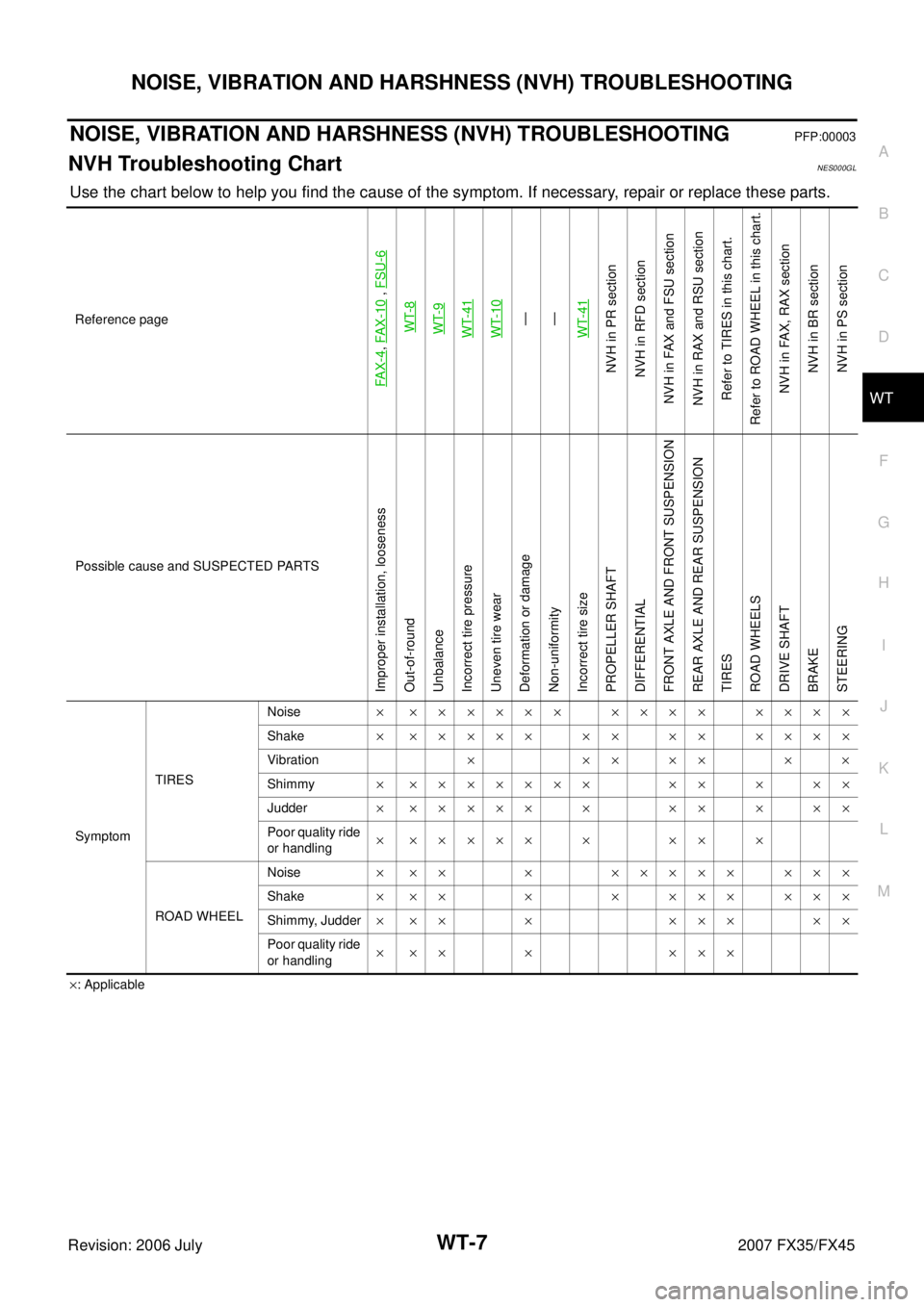
NOISE, VIBRATION AND HARSHNESS (NVH) TROUBLESHOOTINGPFP:00003
NVH Troubleshooting ChartNES000GL
Use the chart below to help you find the cause of the symptom. If necessary, repair or replace these parts.
×: Applicable
Reference page
FAX-4
,
FAX-10
, FSU-6
WT-8WT-9WT-41WT-10—
—
WT-41
NVH in PR section
NVH in RFD section
NVH in FAX and FSU section
NVH in RAX and RSU section Refer to TIRES in this chart.
Refer to ROAD WHEEL in this chart.
NVH in FAX, RAX sectionNVH in BR sectionNVH in PS section
Possible cause and SUSPECTED PARTS
Improper installation, looseness
Out-of-round
Unbalance
Incorrect tire pressure
Uneven tire wear
Deformation or damage
Non-uniformity
Incorrect tire size
PROPELLER SHAFT
DIFFERENTIAL
FRONT AXLE AND FRONT SUSPENSION
REAR AXLE AND REAR SUSPENSION
TIRES
ROAD WHEELS
DRIVE SHAFT
BRAKE
STEERING
Symptom TIRES Noise
× ×××××× ×××× ××××
Shake × ××××× ×× ×× ××××
Vibration ×××××××
Shimmy × ××××××× ×× × ××
Judder × ××××× × ×× × ××
Poor quality ride
or handling × ××××× × ×× ×
ROAD WHEEL Noise
× ×× × ××××× ×××
Shake × ×× × × ××× ×××
Shimmy, Judder × ×× × ××× ××
Poor quality ride
or handling × ×× × ×××