Page 3832 of 4366
PR-6
FRONT PROPELLER SHAFT
Revision: 2006 July 2007 FX35/FX45
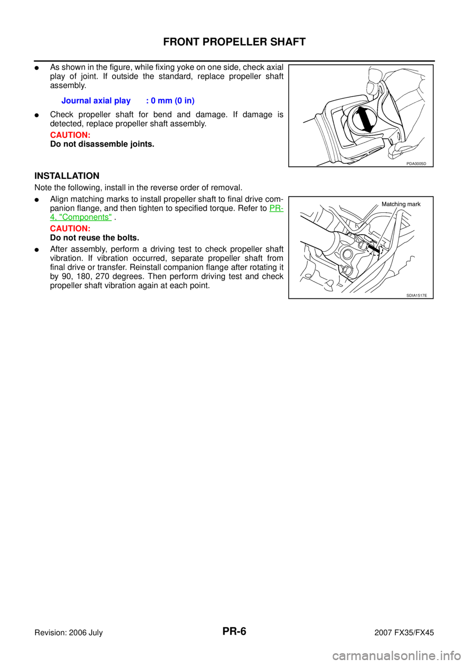
�As shown in the figure, while fixing yoke on one side, check axial
play of joint. If outside the standard, replace propeller shaft
assembly.
�Check propeller shaft for bend and damage. If damage is
detected, replace propeller shaft assembly.
CAUTION:
Do not disassemble joints.
INSTALLATION
Note the following, install in the reverse order of removal.
�Align matching marks to install propeller shaft to final drive com-
panion flange, and then tighten to specified torque. Refer to PR-
4, "Components" .
CAUTION:
Do not reuse the bolts.
�After assembly, perform a driving test to check propeller shaft
vibration. If vibration occurred, separate propeller shaft from
final drive or transfer. Reinstall companion flange after rotating it
by 90, 180, 270 degrees. Then perform driving test and check
propeller shaft vibration again at each point. Journal axial play : 0 mm (0 in)
PDA0005D
SDIA1517E
Page 3833 of 4366

REAR PROPELLER SHAFT PR-7
C E F
G H
I
J
K L
M A
B
PR
Revision: 2006 July 2007 FX35/FX45
REAR PROPELLER SHAFTPFP:37000
On-Vehicle InspectionNDS000AW
APPEARANCE AND NOISE INSPECTION
�Check the propeller shaft tube surface for dents or cracks. If damaged, replace propeller shaft assembly.
�If center bearing is noisy or damaged, replace center bearing.
PROPELLER SHAFT VIBRATION
If vibration is present at high speed, inspect propeller shaft runout first.
1. Measure propeller shaft runout at runout measuring points by rotating final drive companion flange with hands. For measuring
point, refer to PR-4, "
Propeller Shaft Runout Measuring Point" .
2. If runout still exceeds specifications, separate propeller shaft at final drive companion flange; then rotate companion flange 60,
120, 180, 240, 300 degrees and install propeller shaft.
3. Check runout again. If runout still exceeds specifications, replace propeller shaft assembly.
4. Check the vibration by driving vehicle.
Propeller Shaft Runout Measuring Point
� 2WD models (3S80A-1VL107 type)
� AWD models (3F80A-1VL107 type) Propeller shaft runout limit : 0.8 mm (0.031 in)
SDIA1781E
Dimension A: 192 mm (7.56 in)
B: 190 mm (7.48 in)
C: 185 mm (7.28 in)
SDIA1581E
Dimension A: 162 mm (6.38 in) B: 245 mm (9.65 in)
C: 185 mm (7.28 in)
SDIA1779E
Page 3835 of 4366

REAR PROPELLER SHAFT PR-9
C E F
G H
I
J
K L
M A
B
PR
Revision: 2006 July 2007 FX35/FX45
Removal and InstallationNDS000AY
REMOVAL
1. Move the A/T select lever to N position and release the parking brake.
2. Remove the tunnel stay with power tool. Refer to RSU-5, "
REAR
SUSPENSION ASSEMBLY" .
3. Remove the center muffler with power tool. Refer to EX-3,
"EXHAUST SYSTEM" .
4. Loosen mounting nuts of center bearing mounting brackets with power tool.
CAUTION:
Tighten mounting nuts temporarily.
5. For 2WD models
�Put matching marks on propeller shaft rebro joint with final
drive companion flange.
CAUTION:
For matching mark, use paint. Do not damage propeller
shaft and companion flange.
For AWD models
�Put matching marks on propeller shaft flange yoke with trans-
fer companion flange and on rebro joint with final drive com-
panion flange.
CAUTION:
For matching mark, use paint. Do not damage propeller shaft flange yoke, rebro joint and com-
panion flanges.
6. Remove propeller shaft fixing bolts and nuts.
7. Remove center bearing mounting bracket fixing nuts.
8. Remove propeller shaft.
CAUTION:
If constant velocity joint was bent during propeller shaft assembly removal, installation, or trans-
portation, its boot may be damaged. Wrap boot interference area to metal part with shop cloth or
rubber to protect boot from breakage.
PDIA0744E
PDIA0402E
PDIA0470E
Page 3837 of 4366

REAR PROPELLER SHAFT PR-11
C E F
G H
I
J
K L
M A
B
PR
Revision: 2006 July 2007 FX35/FX45
INSTALLATION
Note the following, and install in the reverse order of removal.
CAUTION:
Avoid damaging the rebro joint boot, protect it with a shop towel or equivalent.
�Align matching marks to install propeller shaft to final drive and transfer (AWD models only) companion
flanges, and then tighten to specified torque. Refer to PR-8, "
Components" .
�Install center bearing mounting bracket (Upper) with its arrow
mark facing forward.
�Adjust position of mounting bracket sliding back and forth to pre-
vent play in thrust direction of center bearing insulator. Install
bracket to vehicle.
�After assembly, perform a driving test to check propeller shaft
vibration. If vibration occurred, separate propeller shaft from
final drive. Reinstall companion flange after rotating it by 60,
120, 180, 240, 300 degrees. Then perform driving test and
check propeller shaft vibration again at each point.
�If propeller shaft or final drive has been replaced, connect them
as follows:
1. Install the propeller shaft while aligning its matching mark A with the matching mark B on the joint as close as possible.
2. Tighten the joint bolts to the specified torque. Refer to PR-8,
"Components" .
CAUTION:
Do not reuse the bolts, nuts and washers.
PDIA0017E
SDIA2049E
Page 3840 of 4366

Revision: 2006 July 2007 FX35/FX45
SERVICE DATA AND SPECIFICATIONS (SDS)PFP:00030
General SpecificationsNDS000B0
2WD MODELS
AW D M OD E LS
Journal Axal Pl")
PR-14
SERVICE DATA AND SPECIFICATIONS (SDS)
Revision: 2006 July 2007 FX35/FX45
SERVICE DATA AND SPECIFICATIONS (SDS)PFP:00030
General SpecificationsNDS000B0
2WD MODELS
AW D M OD E LS
Journal Axal PlayNDS000B1
Propeller Shaft RunoutNDS000B2
Applied model VQ35DE
Propeller shaft model 3S80A-1VL107
Number of joints 3
Coupling method with transmission Sleeve type
Coupling method with rear final drive Rebro joint type
Shaft length 1st (Spider to spider) 795 mm (31.30 in)
2nd (Spider to rebro joint center) 681 mm (35.51 in)
Shaft outer diameter 1st 82.6 mm (3.25 in)
2nd 82.6 mm (3.25 in)
Applied model VQ35DE VK45DE
Front Propeller shaft model 2S56A Number of joints 2
Coupling method with transfer Sleeve type
Coupling method with front final drive Flange type
Shaft length (Spider to spider) 763 mm (30.04 in)
Shaft outer diameter 42.7 mm (1.68 in)
Rear Propeller shaft model 3F80A-1VL107 Number of joints 3
Coupling method with transfer Flange type
Coupling method with rear final drive Rebro joint type
Shaft length 1st (Spider to spider) 399 mm (15.71 in)
2nd (Spider to rebro joint center) 753 mm (29.65 in)
Shaft outer
diameter 1st 82.6 mm (3.25 in)
2nd 82.6 mm (3.25 in)
Model Front propeller shaft Rear propeller shaft
2S56A 3S80A-1VL107 3F80A-1VL107
Journal axial play 0 mm (0 in)
Model Front propeller shaft Rear propeller shaft
2S56A 3S80A-1VL107 3F80A-1VL107
Propeller shaft runout limit 0.8 mm (0.031 in)
Page 3847 of 4366
 TROUBLESHOOTING PS-7
C
D E
F
H I
J
K L
M A
B
PS
Revision: 2006 July 2007 FX35/FX45
NOISE, VIBRATION AND HARSHNESS (NVH) TROUBLESHOOTINGPFP:00003
NVH T")
NOISE, VIBRATION AND HARSHNESS (NVH) TROUBLESHOOTING PS-7
C
D E
F
H I
J
K L
M A
B
PS
Revision: 2006 July 2007 FX35/FX45
NOISE, VIBRATION AND HARSHNESS (NVH) TROUBLESHOOTINGPFP:00003
NVH Troubleshooting ChartNGS000BS
Use chart below to help you find the cause of the symptom. If necessary, repair or replace these parts.
×: Applicable Reference page
PS-8PS-8PS-24PS-24PS-24PS-8PS-10PS-10
EM-15
,
EM-174PS-10PS-13PS-18PS-13PS-13PS-18
NVH in PR section
NVH in RFD section
NVH in FAX, RAX, FSU, RSU section NVH in WT section
NVH in WT section
NVH in FAX section
NVH in BR section
Possible cause and suspected parts
Fluid level
Air in hydraulic system
Outer socket ball joint swinging force
Outer socket ball joint rotating torque
Outer socket ball joint end play
Steering fluid leakage
Steering wheel play
Steering gear rack sliding force
Drive belt looseness
Improper steering wheel
Improper installation or looseness of tilt lock lever
Mounting rubber deterioration
Steering column deformation or damage
Improper installation or looseness of steering column
Steering linkage looseness
PROPELLER SHAFT
DIFFERENTIAL
AXLE and SUSPENSION
TIRES
ROAD WHEEL
DRIVE SHAFT
BRAKES
Symptom STEERING Noise
× × ××××× × × ×××××× ×
Shake ××× × ×××× ×
Vibration ××××× × ×× ×
Shimmy ××× × ××× ×
Judder × × ××× ×
Page 3853 of 4366

STEERING COLUMN PS-13
C
D E
F
H I
J
K L
M A
B
PS
Revision: 2006 July 2007 FX35/FX45
STEERING COLUMNPFP:48810
Removal and InstallationNGS000BY
COMPONENTS
CAUTION:
�Care must be taken not to give axial impact to steering column assembly during removal and
installation.
�Care must be taken not to move steering gear during removal of steering column assembly.
REMOVAL
1. Set vehicle to the straight ahead-direction.
2. Remove driver air bag module from steering wheel. Refer to SRS-42, "
DRIVER AIR BAG MODULE" .
3. Disconnect steering switch connector, remove steering wheel lock nut, then remove steering wheel. Refer to SRS-44, "
SPIRAL CABLE" .
4. Remove steering column cover. Refer to IP-10, "
INSTRUMENT PANEL ASSEMBLY" .
5. Remove combination switch & spiral cable from steering column assembly. Refer to SRS-44, "
SPIRAL
CABLE" .
6. Remove instrument lower panel (driver side). Refer to IP-10, "
INSTRUMENT PANEL ASSEMBLY" .
7. Remove combination meter. Refer to IP-10, "
INSTRUMENT PANEL ASSEMBLY" .
1. Steering wheel 2. Combination switch & spiral cable 3. Steering column assembly
4. Collar 5. Hole cover seal 6. Clamp
7. Hole cover 8. Lower shaft 9. Lower joint
Refer to GI-11, "
Components" , for the symbols in the figure.
SGIA1612E
Page 3868 of 4366

PS-28
POWER STEERING GEAR AND LINKAGE
Revision: 2006 July 2007 FX35/FX45
18. Install large-diameter side of boot to gear housing assembly.
19. Install small-diameter side of boot to the mounting groove of inner socket boot.
20. Install boot clamp to the small-diameter side of boot.
21. Install boot clamp to the large-diameter side of boot.
a. Tighten large-diameter side of RH/LH boot with boot clamp (stainless wire).
b. After wrapping clamp around boot groove for two turns, insert screwdriver in loop on both ends of wire. Twist 4 to 4.5 turns
while pulling with a force of approx. 98 N (10 kg, 22 lb).
c. Twist boot clamp as shown in the figure, pay attention to rela- tionship between winding and twisting directions.
22. Install cylinder tubes to gear housing assembly.
23. Install lock nut and outer socket to inner socket.
Measuring point Axial direction of rack 5 mm (0.2 in) away from end of gear housing
Radius direction of rack Shaft direction of adjusting screw
SGIA1325E
Wire length “L” : 390 mm (15.35 in)
SGIA0163E
SGIA0164E
SGIA0544E