Page 3873 of 4366
NGS000C8
COMPONENTS
INSPECTION BEFORE DISASSEMBLY
Disa")
POWER STEERING OIL PUMP PS-33
C
D E
F
H I
J
K L
M A
B
PS
Revision: 2006 July 2007 FX35/FX45
Disassembly and Assembly (VQ35DE Models)NGS000C8
COMPONENTS
INSPECTION BEFORE DISASSEMBLY
Disassemble power steering oil pump only if the following items are found.
�Oil leakage from oil pump
�Deformed or damaged pulley
�Poor performance
DISASSEMBLY
NOTE:
Fix oil pump in vise as the occasion demands.
CAUTION:
When retaining drive shaft in a vise, always use copper or aluminum plates between vise and shaft.
1. Unscrew four rear cover bolts and remove rear cover from body assembly.
2. Remove rear side plate from cartridge, then remove Teflon ring and O-ring from rear side plate.
3. Remove rotor snap ring with snap ring pliers, and remove pulley from body assembly.
CAUTION:
When removing rotor snap ring, be careful not to damage
pulley shaft.
4. Remove oil seal from body assembly.
1. Rear cover 2. Teflon ring 3. O-ring
4. Rear side plate 5. Rotor snap ring 6. Dowel pin
7. Cam ring 8. Rotor 9. Vane
10. Cartridge 11. Front side plate 12. O-ring
13. Flow control valve A 14. Spring 15. Flow control valve B assembly
16. Body assembly 17. Oil seal 18. Pulley
19. O-ring 20. Suction pipe 21. Bracket
SGIA1679E
SGIA0059E
Page 3874 of 4366

PS-34
POWER STEERING OIL PUMP
Revision: 2006 July 2007 FX35/FX45
5. Remove cam ring, rotor, vane, front side plate, flow control valve
A, spring, flow control valve B assembly and O-ring from body
assembly.
CAUTION:
Be careful not to drop and deform flow control valve A and
flow control valve B assembly.
6. Remove suction pipe from body assembly.
7. Remove O-ring from suction pipe.
8. Remove bracket from body assembly.
INSPECTION AFTER DISASSEMBLY
Body Assembly and Rear Cover Inspection
Check body assembly and rear cover for internal damage. Replace rear cover if it is damaged. Replace oil
pump assembly if body assembly is damaged.
Cartridge Assembly Inspection
Check cam ring, rotor and vane for damage. Replace cartridge assembly if necessary.
Side Plate Inspection
Check side plate (front and rear) for damage. Side plate (front and rear) must be replaced as a set if they are
damaged.
Flow Control Valve Inspection
Check flow control valve A, flow control valve spring and flow control valve B assembly for damage. Replace if
there are.
ASSEMBLY
NOTE:
Fix oil pump in vise as occasion demands.
CAUTION:
When retaining drive shaft in a vise, always use copper or aluminum plates between vise and shaft.
1. Apply recommended grease to oil seal lips. Apply recommended fluid to around oil seal, and then install oil seal to body assembly
using the drift [SST].
2. If dowel pin has been removed, insert it into body assembly by hand. If it cannot be inserted by hand, lightly tap with a hammer.
3. Install flow control valve A, flow control valve spring and flow control valve B assembly to locations shown in the figure.
SGIA0526E
SGIA0527E
SGIA0526E
Page 3877 of 4366
NGS000C9
COMPONENTS
INSPECTION BEFORE DISASSEMBLY
Disa")
POWER STEERING OIL PUMP PS-37
C
D E
F
H I
J
K L
M A
B
PS
Revision: 2006 July 2007 FX35/FX45
Disassembly and Assembly (VK45DE Models)NGS000C9
COMPONENTS
INSPECTION BEFORE DISASSEMBLY
Disassemble power steering oil pump only if the following items are found.
�Oil leakage from oil pump.
�Deformed or damaged pulley
�Poor performance
DISASSEMBLY
NOTE:
Fix oil pump in vise as the occasion demands.
CAUTION:
When retaining drive shaft in a vise, always use copper or aluminum plates between vise and shaft.
1. Unscrew three bracket bolts and remove bracket from rear cover.
2. Unscrew four rear cover bolts and remove rear cover from body assembly.
3. Remove gasket from body assembly.
4. Remove lock pin, cartridge and side plate from body assembly.
5. Remove pulley from drive shaft assembly.
1. Bracket 2. Rear cover 3. Gasket
4. Lock pin 5. Cam ring 6. Rotor
7. Vane 8. Cartridge 9. Side plate
10. O-ring 11. Body assembly 12. Oil seal
13. Drive shaft assembly 14. Snap ring 15. Pulley
16. Spring washer 17. Spring 18. Flow control valve
19. O-ring 20. Connector bolt 21. Joint
22. Washer 23. Suction pipe 24. O-ring
SGIA1680E
Page 3878 of 4366

PS-38
POWER STEERING OIL PUMP
Revision: 2006 July 2007 FX35/FX45
6. Remove snap ring from drive shaft assembly and press out it.
CAUTION:
When removing snap ring, be careful not to damage drive
shaft assembly.
7. Using a screwdriver, remove oil seal for body assembly.
8. Remove O-ring from body assembly.
9. Loosen lock nut and remove washer, O-ring, joint then remove connector bolt, O-ring and pull out flow control valve and spring
from body assembly.
CAUTION:
Be careful not to drop and deform the flow control valve.
10. Remove suction pipe from body assembly.
11. Remove O-ring for suction pipe.
INSPECTION AFTER DISASSEMBLY
Body Assembly and Rear Cover Inspection
Check body assembly and rear cover for internal damage. Replace rear cover if it is damaged. Replace oil
pump assembly if body assembly is damaged.
Cartridge Assembly Inspection
Check cam ring, rotor and vane for damage. Replace cartridge assembly if there are.
Side Plate Inspection
Check side plate for damage. Replace side plate if there are.
Flow Control Valve Inspection
Check flow control valve and spring for damage. Replace if there are.
SST010B
SST034A
SGIA0524E
Page 3879 of 4366

POWER STEERING OIL PUMP PS-39
C
D E
F
H I
J
K L
M A
B
PS
Revision: 2006 July 2007 FX35/FX45
ASSEMBLY
NOTE:
Fix oil pump in vise as vise occasion demands.
CAUTION:
When retaining drive shaft assembly in a vise, always use copper or aluminum plates between vise
and shaft.
1. Apply recommended grease to oil seal lips (1). Apply recom- mended fluid to around oil seal, and then install oil seal to body
assembly.
2. Apply recommended fluid to drive shaft assembly and press drive shaft assembly into body assembly with suitable tool, then
install snap ring.
3. Apply recommended fluid to O-ring and Install O-ring into body assembly.
4. Install side plate to body assembly.
5. Install lock pin into lock pin hole, and install cam-ring as shown in the figure.
�When installing cam-ring, turn carved face with a letter (E) of
it to rear cover.
CAUTION:
Do not confuse the assembling direction of cam ring. If
cam ring is installed facing the incorrect direction, it may
cause pump operation malfunction.
6. Install rotor to body assembly.
SGIA1150E
SGIA0422E
SGIA0591E
Page 3880 of 4366
PS-40
POWER STEERING OIL PUMP
Revision: 2006 July 2007 FX35/FX45
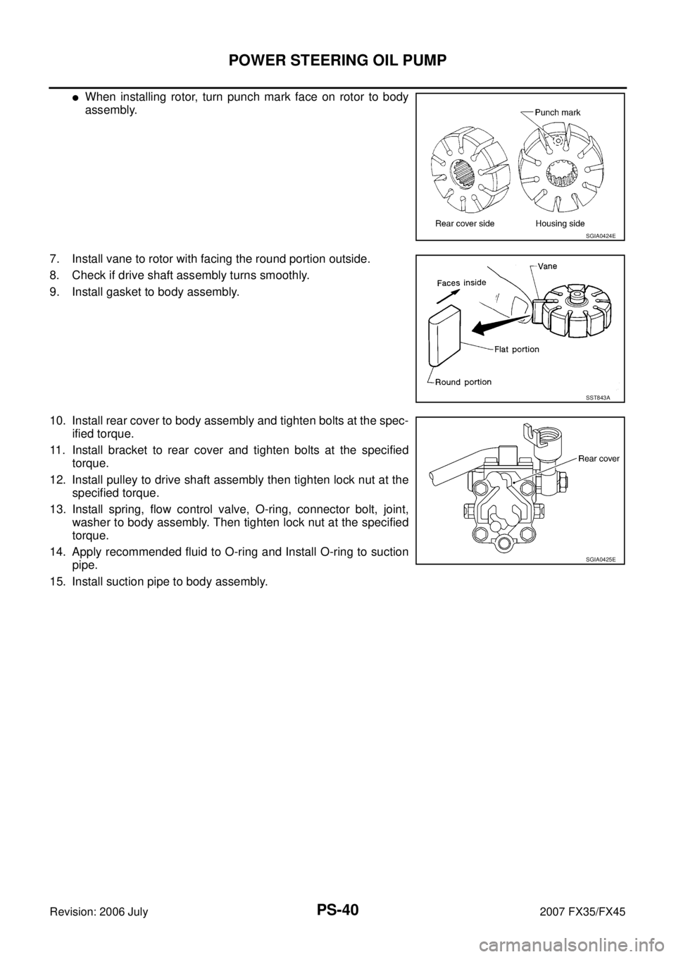
�When installing rotor, turn punch mark face on rotor to body
assembly.
7. Install vane to rotor with facing the round portion outside.
8. Check if drive shaft assembly turns smoothly.
9. Install gasket to body assembly.
10. Install rear cover to body assembly and tighten bolts at the spec- ified torque.
11. Install bracket to rear cover and tighten bolts at the specified torque.
12. Install pulley to drive shaft assembly then tighten lock nut at the specified torque.
13. Install spring, flow control valve, O-ring, connector bolt, joint, washer to body assembly. Then tighten lock nut at the specified
torque.
14. Apply recommended fluid to O-ring and Install O-ring to suction pipe.
15. Install suction pipe to body assembly.
SGIA0424E
SST843A
SGIA0425E
Page 3887 of 4366

RAX-1
REAR AXLE
D DRIVELINE/AXLE
CONTENTS
C E F
G H
I
J
K L
M
SECTION
A
B
RAX
Revision: 2006 July 2007 FX35/FX45
REAR AXLE
PRECAUTIONS .......................................................... 2
Caution ................................................................ ..... 2
PREPARATION ...................................................... ..... 3
Special Service Tools (SST) ................................ ..... 3
Commercial Service Tools ................................... ..... 3
NOISE, VIBRATION AND HARSHNESS (NVH)
TROUBLESHOOTING ........................................... ..... 4
NVH Troubleshooting Chart ................................ ..... 4
REAR WHEEL HUB AND KNUCKLE ................... ..... 5
On-Vehicle Inspection ......................................... ..... 5
WHEEL BEARING INSPECTION .................... ..... 5
Removal and Installation ..................................... ..... 5
COMPONENTS ............................................... ..... 5
REMOVAL ........................................................ ..... 5
INSPECTION AFTER REMOVAL .................... ..... 6 INSTALLATION ................................................
..... 6
Disassembly and Assembly ................................. ..... 7
DISASSEMBLY ................................................ ..... 7
INSPECTION AFTER DISASSEMBLY ............. ..... 7
ASSEMBLY ...................................................... ..... 8
INSPECTION AFTER ASSEMBLY ................... ..... 8
REAR DRIVE SHAFT ............................................ ..... 9
Removal and Installation ..................................... ..... 9
COMPONENTS ................................................ ..... 9
REMOVAL ........................................................ ..... 9
INSPECTION AFTER REMOVAL .................... ..... 9
INSTALLATION ................................................ ..... 9
Disassembly and Assembly ................................. ... 10
COMPONENTS ................................................ ... 10
DISASSEMBLY ................................................ ... 10
INSPECTION AFTER DISASSEMBLY ............. ... 11
ASSEMBLY ...................................................... ... 12
SERVICE DATA AND SPECIFICATIONS (SDS) ... ... 15
Wheel Bearing ..................................................... ... 15
Drive Shaft ........................................................... ... 15
Page 3888 of 4366
RAX-2
PRECAUTIONS
Revision: 2006 July 2007 FX35/FX45
PRECAUTIONSPFP:00001
CautionNDS000CD
Observe the following precautions when disassembling and servicing drive shaft.
�Perform work in a location which is as dust-free as possible.
�Before disassembling and servicing, clean the outside of parts.
�Prevention of the entry of foreign objects must be taken into account during disassembly of the service
location.
�Disassembled parts must be carefully reassembled in the correct order. If work is interrupted, a clean
cover must be placed over parts.
�Paper shop cloths must be used. Fabric shop cloths must not be used because of the danger of lint adher-
ing to parts.
�Disassembled parts (except for rubber parts) should be cleaned with kerosene which shall be removed by
blowing with air or wiping with paper shop cloths.