Page 1225 of 4366
OVERHEATING CAUSE ANALYSIS CO-35
[VK45DE]
C
D E
F
G H
I
J
K L
M A
CO
Revision: 2006 July 2007 FX35/FX45
Except cool-
ing system
parts mal-
function — Overload on engine
Abusive driving
High engine rpm under no
load
Driving in low gear for
extended time
Driving at extremely high
speed
Powertrain system mal-
function
—
Installed improper size
wheels and tires
Dragging brakes
Improper ignition timing
Blocked or restricted air
flow Blocked bumper —
—
Blocked radiator grille
Installed car brassiere
Mud contamination or
paper clogging
Blocked radiator —
Blocked condenser Blocked air flow
Installed large fog lamp
Symptom Check items
Page 1228 of 4366
![INFINITI FX35 2007 Service Manual CO-38
[VK45DE]
ENGINE COOLANT
Revision: 2006 July 2007 FX35/FX45
ENGINE COOLANTPFP:KQ100
InspectionNBS003KI
LEVEL CHECK
�Check if the reservoir tank engine coolant level is within the
“MIN” to �](/manual-img/42/57018/w960_57018-1227.png "INFINITI FX35 2007 Service Manual CO-38
[VK45DE]
ENGINE COOLANT
Revision: 2006 July 2007 FX35/FX45
ENGINE COOLANTPFP:KQ100
InspectionNBS003KI
LEVEL CHECK
�Check if the reservoir tank engine coolant level is within the
“MIN” to �")
CO-38
[VK45DE]
ENGINE COOLANT
Revision: 2006 July 2007 FX35/FX45
ENGINE COOLANTPFP:KQ100
InspectionNBS003KI
LEVEL CHECK
�Check if the reservoir tank engine coolant level is within the
“MIN” to “MAX” when engine is cool.
�Adjust the engine coolant level as necessary.
LEAK CHECK
�To check for leaks, apply pressure to the cooling system with
radiator cap tester (commercial service tool) and radiator cap
tester adapter (SST).
WARNING:
Do not remove radiator cap when engine is hot. Serious
burns could occur from high-pressure engine coolant
escaping from thermostat housing.
CAUTION:
Higher testing pressure than specified may cause radiator
damage.
NOTE:
In a case engine coolant decreases, replenish radiator with engine coolant.
�If anything is found, repair or replace damaged parts.
Changing Engine CoolantNBS003KJ
WARNING:
�To avoid being scalded, do not change engine coolant when engine is hot.
�Wrap a thick cloth around radiator cap and carefully remove radiator cap. First, turn radiator cap a
quarter of a turn to release built-up pressure. Then turn radiator cap all the way.
DRAINING ENGINE COOLANT
1. Remove front engine undercover with power tool.
2. Open radiator drain plug at the bottom of radiator, and then remove radiator cap.
When draining all of engine coolant in the system, open water drain plugs on cylinder block. Refer
to EM-249, "
DISASSEMBLY" .
3. Remove reservoir tank as necessary, and drain engine coolant and clean reservoir tank before installing.
4. Check drained engine coolant for contaminants such as rust, corrosion or discoloration. If contaminated, flush the engine cooling system. Refer to CO-40, "
FLUSHING COOLING SYSTEM" .
SMA412B
Testing pressure : 157 kPa (1.6 kg/cm2 , 23 psi)
PBIC1528E
SBIA0444E
Page 1230 of 4366
![INFINITI FX35 2007 Service Manual CO-40
[VK45DE]
ENGINE COOLANT
Revision: 2006 July 2007 FX35/FX45
9. Repeat steps 4 through 7 two or more times with radiator cap installed until engine coolant level no longer
drops.
10. Check cooli](/manual-img/42/57018/w960_57018-1229.png "INFINITI FX35 2007 Service Manual CO-40
[VK45DE]
ENGINE COOLANT
Revision: 2006 July 2007 FX35/FX45
9. Repeat steps 4 through 7 two or more times with radiator cap installed until engine coolant level no longer
drops.
10. Check cooli")
CO-40
[VK45DE]
ENGINE COOLANT
Revision: 2006 July 2007 FX35/FX45
9. Repeat steps 4 through 7 two or more times with radiator cap installed until engine coolant level no longer
drops.
10. Check cooling system for leaks with engine running.
11. Warm up engine, and check for sound of engine coolant flow while running engine from idle up to 3,000 rpm with heater temperature controller set at several position between “COOL” and “WARM”.
�Sound may be noticeable at heater unit.
12. Repeat step 11 three times.
13. If sound is heard, bleed air from cooling system by repeating steps 4 through 7 until engine coolant level no longer drops.
FLUSHING COOLING SYSTEM
1. Install reservoir tank, and radiator drain plug.
CAUTION:
Be sure to clean drain plug and install with new O-ring.
If water drain plugs on cylinder block are removed, close and tighten them. Refer to EM-253,
"ASSEMBLY" .
2. Remove air relief plug on heater hose.
3. Fill thermostat housing with water until water spills from the air relief hole, then close air relief plug. Fill thermostat housing and reservoir tank with water and reinstall radiator cap.
4. Run engine and warm it up to normal operating temperature.
5. Rev engine two or three times under no-load.
6. Stop engine and wait until it cools down.
7. Drain water from the system. Refer to CO-38, "
DRAINING ENGINE COOLANT" .
8. Repeat steps 1 through 7 until clear water begins to drain from radiator. Radiator drain plug:
: 1.19 N·m (0.12 kg-m, 11 in-lb)
PBIC1530E
Page 1233 of 4366
![INFINITI FX35 2007 Service Manual RADIATOR CO-43
[VK45DE]
C
D E
F
G H
I
J
K L
M A
CO
Revision: 2006 July 2007 FX35/FX45
11. Lift up and remove radiator.
CAUTION:
Do not damage or scratch A/C condenser and radiator core](/manual-img/42/57018/w960_57018-1232.png "INFINITI FX35 2007 Service Manual RADIATOR CO-43
[VK45DE]
C
D E
F
G H
I
J
K L
M A
CO
Revision: 2006 July 2007 FX35/FX45
11. Lift up and remove radiator.
CAUTION:
Do not damage or scratch A/C condenser and radiator core")
RADIATOR CO-43
[VK45DE]
C
D E
F
G H
I
J
K L
M A
CO
Revision: 2006 July 2007 FX35/FX45
11. Lift up and remove radiator.
CAUTION:
Do not damage or scratch A/C condenser and radiator core
when removing.
INSTALLATION
Install in the reverse order of removal.
INSPECTION AFTER INSTALLATION
�Check for leaks of engine coolant using radiator cap tester adapter [SST: EG17650301 (J33984-A)] and
radiator cap tester (commercial service tool). Refer to CO-38, "
LEAK CHECK" .
�Start and warm up engine. Visually Check if there is no leaks of engine coolant and A/T fluid.
Checking Radiator CapNBS003KL
�Check valve seat of radiator cap.
–Check if valve seat is swollen to the extent that the edge of the
plunger cannot be seen when watching it vertically from the top.
–Check if valve seat has no soil and damage.
�Pull negative-pressure valve to open it, and make sure that it
close completely when released.
–Make sure that there is no dirt or damage on the valve seat of
radiator cap negative-pressure valve.
–Make sure that there are no unusualness in the opening and
closing conditions of negative-pressure valve.
�Check radiator cap relief pressure.
–When connecting radiator cap to the radiator cap tester adapter
(SST) and the radiator cap tester (Commercial service tool),
apply engine coolant to the cap seal surface.
�Replace radiator cap if there is an unusualness.
PBIC1536E
PBIC2816E
SMA967B
Standard : 78 - 98 kPa (0.8 - 1.0 kg/cm2 , 11 - 14 psi)
Limit : 59 kPa (0.6 kg/cm
2 , 9 psi)
SLC755A
Page 1241 of 4366
![INFINITI FX35 2007 Service Manual WATER PUMP CO-51
[VK45DE]
C
D E
F
G H
I
J
K L
M A
CO
Revision: 2006 July 2007 FX35/FX45
WAT E R P U MPPFP:21020
ComponentsNBS005S0
Removal and InstallationNBS003KR
CAUTION:
�When removin](/manual-img/42/57018/w960_57018-1240.png "INFINITI FX35 2007 Service Manual WATER PUMP CO-51
[VK45DE]
C
D E
F
G H
I
J
K L
M A
CO
Revision: 2006 July 2007 FX35/FX45
WAT E R P U MPPFP:21020
ComponentsNBS005S0
Removal and InstallationNBS003KR
CAUTION:
�When removin")
WATER PUMP CO-51
[VK45DE]
C
D E
F
G H
I
J
K L
M A
CO
Revision: 2006 July 2007 FX35/FX45
WAT E R P U MPPFP:21020
ComponentsNBS005S0
Removal and InstallationNBS003KR
CAUTION:
�When removing water pump, be careful not to get engine coolant on drive belts.
�Water pump can not be disassembled and should be replaced as a unit.
�After installing water pump, connect hose and clamp securely, then check for leaks using radiator
cap tester (commercial service tool) and radiator cap tester adapter [SST: EG17650301 (J33984-
A)].
REMOVAL
1. Drain engine coolant from drain plugs on radiator and both side of cylinder block. Refer to CO-38, "Chang-
ing Engine Coolant" and EM-249, "DISASSEMBLY" .
CAUTION:
�Perform this step when engine is cold.
�Do not spill engine coolant on drive belts.
2. Remove following parts:
�Engine front undercover
�Air duct (inlet); Refer to EM-177, "AIR CLEANER AND AIR DUCT" .
�Alternator, water pump and A/C compressor belt; Refer to EM-174, "DRIVE BELTS" .
3. Remove fan coupling with cooling fan, and then fan and water pump pulley.
4. Remove water pump.
�Engine coolant will leak from cylinder block, so have a receptacle ready under vehicle.
CAUTION:
�Handle the water pump vane so that it does not contact any other parts.
�Do not disassemble water pump.
1. Fan and water pump pulley 2. Water pump 3. Gasket
PBIC1538E
Page 1242 of 4366
CO-52
[VK45DE]
WATER PUMP
Revision: 2006 July 2007 FX35/FX45
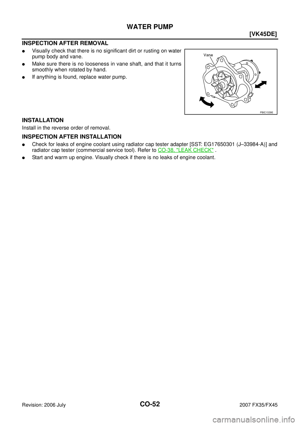
INSPECTION AFTER REMOVAL
�Visually check that there is no significant dirt or rusting on water
pump body and vane.
�Make sure there is no looseness in vane shaft, and that it turns
smoothly when rotated by hand.
�If anything is found, replace water pump.
INSTALLATION
Install in the reverse order of removal.
INSPECTION AFTER INSTALLATION
�Check for leaks of engine coolant using radiator cap tester adapter [SST: EG17650301 (J–33984-A)] and
radiator cap tester (commercial service tool). Refer to CO-38, "
LEAK CHECK" .
�Start and warm up engine. Visually check if there is no leaks of engine coolant.
PBIC1539E
Page 1244 of 4366
![INFINITI FX35 2007 Service Manual CO-54
[VK45DE]
THERMOSTAT AND WATER CONTROL VALVE
Revision: 2006 July 2007 FX35/FX45
�Refer to GI-11, "Components" for symbol marks in the figure.
Removal and InstallationNBS003KS
REMOVAL
1. Drain en](/manual-img/42/57018/w960_57018-1243.png "INFINITI FX35 2007 Service Manual CO-54
[VK45DE]
THERMOSTAT AND WATER CONTROL VALVE
Revision: 2006 July 2007 FX35/FX45
�Refer to GI-11, \"Components\" for symbol marks in the figure.
Removal and InstallationNBS003KS
REMOVAL
1. Drain en")
CO-54
[VK45DE]
THERMOSTAT AND WATER CONTROL VALVE
Revision: 2006 July 2007 FX35/FX45
�Refer to GI-11, "Components" for symbol marks in the figure.
Removal and InstallationNBS003KS
REMOVAL
1. Drain engine coolant from drain plugs on radiator and both side of cylinder block. Refer to CO-38, "Chang-
ing Engine Coolant" and EM-249, "DISASSEMBLY" .
CAUTION:
�Perform this step when engine is cold.
�Do not spill engine coolant on drive belts.
2. Remove engine cover with power tool. Refer to EM-173, "
ENGINE ROOM COVER" .
3. Remove air duct (inlet). Refer to EM-177, "
AIR CLEANER AND AIR DUCT" .
4. Disconnect water suction hose from water inlet.
5. Remove water inlet and thermostat. CAUTION:
Do not disassemble thermostat.
6. Remove intake manifolds (upper and lower). Refer to EM-179, "
INTAKE MANIFOLD" .
7. Disconnect radiator hose (upper) and water hoses from thermostat housing.
8. Disconnect heater hoses from water outlet and heater pipe.
9. Remove thermostat housing, water outlet pipe, water connector, water control valve, water outlet and heater pipe.
CAUTION:
Do not disassemble water control valve.
INSPECTION AFTER REMOVAL
�Make sure that valves both in thermostat and water control valve are completely closing at normal temper-
ature.
�Place a thread so that it is caught in the valves of the thermostat
and water control valve. Immerse fully in a container filled with
water. Heat while stirring. (The example in the figure shows ther-
mostat.)
�The valve opening temperature is the temperature at which the
valve opens and falls from the thread.
�Continue heating. Check the maximum valve lift.
NOTE:
The maximum valve lift standard temperature for water control
valve is the reference value.
� After checking the maximum valve lift, lower the water tempera-
ture and check the valve closing temperature.
Standard values:
�If the malfunctioning condition, when closing valve at normal temperature, or measured values are out of
the standard, replace thermostat and/or water control valve.
INSTALLATION
Note the following, and install in the reverse order of removal.
CAUTION:
Be careful not to spill engine coolant over engine room. Use rag to absorb engine coolant.
D. To heater core E. To cylinder head (left bank) F. To cylinder head (right bank)
G. To intake manifold adapter
SLC252B
Thermostat Water control valve
Valve opening temperature 80 - 84 °C (176 - 183 °F) 93.5 - 96.5 °C (200 - 206 °F)
Maximum valve lift More than 10 mm/ 95
°C
(0.39 in/ 203 °F) More than 8 mm/ 108
°C
(0.315 in/ 226 °F)
Valve closing temperature 77 °C (171 °F) 90 °C (194 °F)
Page 1245 of 4366
![INFINITI FX35 2007 Service Manual THERMOSTAT AND WATER CONTROL VALVE CO-55
[VK45DE]
C
D E
F
G H
I
J
K L
M A
CO
Revision: 2006 July 2007 FX35/FX45
Thermostat and Water Control Valve
�Install thermostat and water control va](/manual-img/42/57018/w960_57018-1244.png "INFINITI FX35 2007 Service Manual THERMOSTAT AND WATER CONTROL VALVE CO-55
[VK45DE]
C
D E
F
G H
I
J
K L
M A
CO
Revision: 2006 July 2007 FX35/FX45
Thermostat and Water Control Valve
�Install thermostat and water control va")
THERMOSTAT AND WATER CONTROL VALVE CO-55
[VK45DE]
C
D E
F
G H
I
J
K L
M A
CO
Revision: 2006 July 2007 FX35/FX45
Thermostat and Water Control Valve
�Install thermostat and water control valve with the whole circum-
ference of each flange part fit securely inside rubber ring. (The
example in the figure shows thermostat.)
�Install thermostat with jiggle valve facing upwards. (The position
deviation may be within the range of ±10 degrees)
�Install water control valve with the up-mark facing up and the
frame center part facing upwards. (The position deviation may
be within the range of ±10 degrees)
Water Outlet Pipe and Heater Pipe
First apply a neutral detergent to O-rings, then quickly insert the insertion parts of the water outlet pipe and
heater pipe into the installation holes.
INSPECTION AFTER INSTALLATION
�Check for leaks of engine coolant using radiator cap tester adapter [SST: EG17650301 (J33984-A)] and
radiator cap tester (commercial service tool). Refer to CO-38, "
LEAK CHECK" .
�Start and warm up engine. Visually check if there is no leaks of engine coolant.
PBIC0157E
PBIC0158E
![INFINITI FX35 2007 Service Manual OVERHEATING CAUSE ANALYSIS CO-35
[VK45DE]
C
D E
F
G H
I
J
K L
M A
CO
Revision: 2006 July 2007 FX35/FX45
Except cool-
ing system
parts mal-
function — Overload on engine
Abusive dri](/manual-img/42/57018/w960_57018-1224.png "INFINITI FX35 2007 Service Manual OVERHEATING CAUSE ANALYSIS CO-35
[VK45DE]
C
D E
F
G H
I
J
K L
M A
CO
Revision: 2006 July 2007 FX35/FX45
Except cool-
ing system
parts mal-
function — Overload on engine
Abusive dri")