Page 1640 of 4366
EC-264
[VQ35DE]
DTC P0133, P0153 A/F SENSOR 1
Revision: 2006 July 2007 FX35/FX45
2. RETIGHTEN AIR FUEL RATIO (A/F) SENSOR 1
Loosen and retighten the air fuel ratio (A/F) sensor 1.
>> GO TO 3.
3. CHECK EXHAUST GAS LEAK
1. Start engine and run it at idle.
2. Listen for an exhaust gas leak before three way catalyst 1.
OK or NG
OK >> GO TO 4.
NG >> Repair or replace.
4. CHECK FOR INTAKE AIR LEAK
Listen for an intake air leak after the mass air flow sensor.
OK or NG
OK >> GO TO 5.
NG >> Repair or replace. Tightening torque: 40 - 60 N-m (4.1 - 6.1 kg-m, 30 - 44 ft-lb)
PBIB2200E
PBIB1922E
Page 1987 of 4366
DTC P2A00, P2A03 A/F SENSOR 1 EC-611
[VQ35DE]
C
D E
F
G H
I
J
K L
M A
EC
Revision: 2006 July 2007 FX35/FX45
2. RETIGHTEN AIR FUEL RATIO (A/F) SENSOR 1
Loosen and retighten the air fuel ratio (A/F) sensor 1.
>> GO TO 3.
3. CHECK FOR INTAKE AIR LEAK
1. Start engine and run it at idle.
2. Listen for an intake air leak after the mass air flow sensor.
OK or NG
OK >> GO TO 4.
NG >> Repair or replace. Tightening torque: 40 - 60 N-m (4.1 - 6.1 kg-m, 30 - 44 ft-lb)
PBIB2200E
Page 2044 of 4366
EC-668
[VQ35DE]
SNOW MODE SWITCH
Revision: 2006 July 2007 FX35/FX45
SNOW MODE SWITCHPFP:25310
DescriptionNBS0040B
The snow mode switch signal is sent to the “unified meter and A/C amp.” from the snow mode switch. The
“unified meter and A/C amp.” then sends the signal to the ECM by CAN communication line.
The snow mode is used for driving or starting the vehicle on snowy roads or slippery areas. If the snow mode
is activated, the vehicle speed will not be accelerated immediately than your original pedal in due to avoid the
vehicle slip. In other words, ECM controls the rapid engine torque change by controlling the electric throttle
control actuator operating speed.
CONSULT-II Reference Value in the Data Monitor ModeNBS0040C
MONITOR ITEM CONDITION SPECIFICATION
SNOW MODE SW
�Ignition switch: ON Snow mode switch: ON ON
Snow mode switch: OFF OFF
Page 2064 of 4366
EC-688
[VK45DE]
PRECAUTIONS
Revision: 2006 July 2007 FX35/FX45
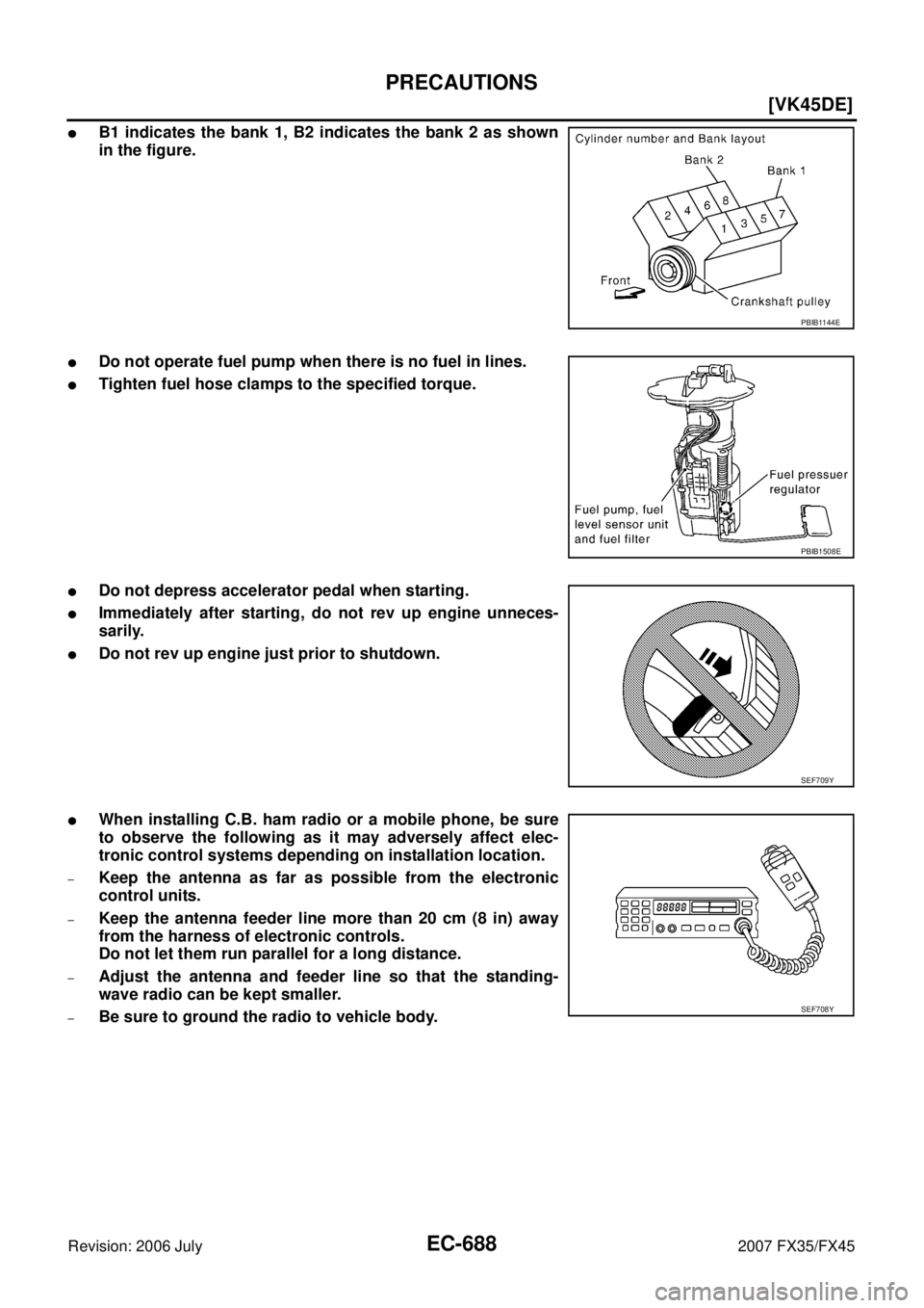
�B1 indicates the bank 1, B2 indicates the bank 2 as shown
in the figure.
�Do not operate fuel pump when there is no fuel in lines.
�Tighten fuel hose clamps to the specified torque.
�Do not depress accelerator pedal when starting.
�Immediately after starting, do not rev up engine unneces-
sarily.
�Do not rev up engine just prior to shutdown.
�When installing C.B. ham radio or a mobile phone, be sure
to observe the following as it may adversely affect elec-
tronic control systems depending on installation location.
–Keep the antenna as far as possible from the electronic
control units.
–Keep the antenna feeder line more than 20 cm (8 in) away
from the harness of electronic controls.
Do not let them run parallel for a long distance.
–Adjust the antenna and feeder line so that the standing-
wave radio can be kept smaller.
–Be sure to ground the radio to vehicle body.
PBIB1144E
PBIB1508E
SEF709Y
SEF708Y
Page 2201 of 4366
![INFINITI FX35 2007 Service Manual DTC P0011, P0021 IVT CONTROL EC-825
[VK45DE]
C
D E
F
G H
I
J
K L
M A
EC
Revision: 2006 July 2007 FX35/FX45
DTC P0011, P0021 IVT CONTROLPFP:23796
DescriptionNBS0042O
SYSTEM DESCRIPTION
*:](/manual-img/42/57018/w960_57018-2200.png "INFINITI FX35 2007 Service Manual DTC P0011, P0021 IVT CONTROL EC-825
[VK45DE]
C
D E
F
G H
I
J
K L
M A
EC
Revision: 2006 July 2007 FX35/FX45
DTC P0011, P0021 IVT CONTROLPFP:23796
DescriptionNBS0042O
SYSTEM DESCRIPTION
*:")
DTC P0011, P0021 IVT CONTROL EC-825
[VK45DE]
C
D E
F
G H
I
J
K L
M A
EC
Revision: 2006 July 2007 FX35/FX45
DTC P0011, P0021 IVT CONTROLPFP:23796
DescriptionNBS0042O
SYSTEM DESCRIPTION
*: This signal is sent to the ECM through CAN communication line
This mechanism hydraulically controls cam phases continuously with the fixed operating angle of the intake
valve.
The ECM receives signals such as crankshaft position, camshaft position, engine speed, and engine coolant
temperature. Then, the ECM sends ON/OFF pulse duty signals to the intake valve timing (IVT) control sole-
noid valve depending on driving status. This makes it possible to control the shut/open timing of the intake
valve to increase engine torque in low/mid speed range and output in high-speed range.
COMPONENT DESCRIPTION
Intake Valve Timing Control Solenoid Valve
Intake Valve Timing (IVT) control solenoid valve is activated by ON/
OFF pulse duty (ratio) signals from the ECM.
The IVT control solenoid valve changes the oil amount and direction
of flow through intake valve timing control unit or stops oil flow.
The longer pulse width advances valve angle.
The shorter pulse width retards valve angle.
When ON and OFF pulse widths become equal, the solenoid valve
stops oil pressure flow to fix the intake valve angle at the control
position.
Sensor Input signal to ECM function ECM Actuator
Crankshaft position sensor (POS)
Camshaft position sensor (PHASE) Engine speed
Intake valve
timing control Intake valve timing control
solenoid valve
Intake valve timing control position sensor Intake valve timing signal
Engine coolant temperature sensor Engine coolant temperature
Wheel sensor Vehicle speed*
PBIB3276E
PBIB1842E
Page 2312 of 4366
EC-936
[VK45DE]
DTC P0133, P0153 A/F SENSOR 1
Revision: 2006 July 2007 FX35/FX45
2. RETIGHTEN AIR FUEL RATIO (A/F) SENSOR 1
1. Loosen and retighten the air fuel ratio (A/F) sensor 1.
>> GO TO 3.
3. CHECK EXHAUST GAS LEAK
1. Start engine and run it at idle.
2. Listen for an exhaust gas leak before three way catalyst (manifold).
OK or NG
OK >> GO TO 4.
NG >> Repair or replace.
4. CHECK FOR INTAKE AIR LEAK
Listen for an intake air leak after the mass air flow sensor.
OK or NG
OK >> GO TO 5.
NG >> Repair or replace.
1. A/F sensor 1 (Bank 1) 2. Heated oxygen sensor 2 (Bank 1) 3. Heated oxygen sensor 2 (Bank 1)
harness connector
4. Heated oxygen sensor 2 (Bank 2) harness connector 5. Heated oxygen sensor 2 (Bank 2) 6. A/F sensor 1 (Bank 2)
Tightening torque: 50 N-m (5.1 kg-m, 37 ft-lb)
PBIB3239E
PBIB1216E
Page 2669 of 4366
DTC P2A00, P2A03 A/F SENSOR 1 EC-1293
[VK45DE]
C
D E
F
G H
I
J
K L
M A
EC
Revision: 2006 July 2007 FX35/FX45
2. RETIGHTEN AIR FUEL RATIO (A/F) SENSOR 1
1. Loosen and retighten the air fuel ratio (A/F) sensor 1.
>> GO TO 3.
3. CHECK FOR INTAKE AIR LEAK
1. Start engine and run it at idle.
2. Listen for an intake air leak after the mass air flow sensor.
OK or NG
OK >> GO TO 4.
NG >> Repair or replace.
1. A/F sensor 1 (Bank 1) 2. Heated oxygen sensor 2 (Bank 1) 3. Heated oxygen sensor 2 (Bank 1)
harness connector
4. Heated oxygen sensor 2 (Bank 2) harness connector 5. Heated oxygen sensor 2 (Bank 2) 6. A/F sensor 1 (Bank 2)
Tightening torque: 50 N-m (5.1 kg-m, 37 ft-lb)
PBIB3239E
Page 2726 of 4366
EC-1350
[VK45DE]
SNOW MODE SWITCH
Revision: 2006 July 2007 FX35/FX45
SNOW MODE SWITCHPFP:25130
DescriptionNBS004HV
The snow mode switch signal is sent to the “unified meter and A/C amp.” from the snow mode switch. The
“unified meter and A/C amp.” then sends the signal to the ECM by CAN communication line.
The snow mode is used for driving or starting the vehicle on snowy roads or slippery areas. If the snow mode
is activated, the vehicle speed will not be accelerated immediately than your original pedal in due to avoid the
vehicle slip. In other words, ECM controls the rapid engine torque change by controlling the electric throttle
control actuator operating speed.
CONSULT-II Reference Value in the Data Monitor ModeNBS004HW
MONITOR ITEM CONDITION SPECIFICATION
SNOW MODE SW
�Ignition switch: ON Snow mode switch: ON ON
Snow mode switch: OFF OFF
![INFINITI FX35 2007 Service Manual EC-264
[VQ35DE]
DTC P0133, P0153 A/F SENSOR 1
Revision: 2006 July 2007 FX35/FX45
2. RETIGHTEN AIR FUEL RATIO (A/F) SENSOR 1
Loosen and retighten the air fuel ratio (A/F) sensor 1.
>> GO TO 3.
3. CHE](/manual-img/42/57018/w960_57018-1639.png "INFINITI FX35 2007 Service Manual EC-264
[VQ35DE]
DTC P0133, P0153 A/F SENSOR 1
Revision: 2006 July 2007 FX35/FX45
2. RETIGHTEN AIR FUEL RATIO (A/F) SENSOR 1
Loosen and retighten the air fuel ratio (A/F) sensor 1.
>> GO TO 3.
3. CHE")
![INFINITI FX35 2007 Service Manual DTC P2A00, P2A03 A/F SENSOR 1 EC-611
[VQ35DE]
C
D E
F
G H
I
J
K L
M A
EC
Revision: 2006 July 2007 FX35/FX45
2. RETIGHTEN AIR FUEL RATIO (A/F) SENSOR 1
Loosen and retighten the air fuel r](/manual-img/42/57018/w960_57018-1986.png "INFINITI FX35 2007 Service Manual DTC P2A00, P2A03 A/F SENSOR 1 EC-611
[VQ35DE]
C
D E
F
G H
I
J
K L
M A
EC
Revision: 2006 July 2007 FX35/FX45
2. RETIGHTEN AIR FUEL RATIO (A/F) SENSOR 1
Loosen and retighten the air fuel r")
![INFINITI FX35 2007 Service Manual EC-668
[VQ35DE]
SNOW MODE SWITCH
Revision: 2006 July 2007 FX35/FX45
SNOW MODE SWITCHPFP:25310
DescriptionNBS0040B
The snow mode switch signal is sent to the “unified meter and A/C amp.” from the s](/manual-img/42/57018/w960_57018-2043.png "INFINITI FX35 2007 Service Manual EC-668
[VQ35DE]
SNOW MODE SWITCH
Revision: 2006 July 2007 FX35/FX45
SNOW MODE SWITCHPFP:25310
DescriptionNBS0040B
The snow mode switch signal is sent to the “unified meter and A/C amp.” from the s")
![INFINITI FX35 2007 Service Manual EC-936
[VK45DE]
DTC P0133, P0153 A/F SENSOR 1
Revision: 2006 July 2007 FX35/FX45
2. RETIGHTEN AIR FUEL RATIO (A/F) SENSOR 1
1. Loosen and retighten the air fuel ratio (A/F) sensor 1.
>> GO TO 3.
3.](/manual-img/42/57018/w960_57018-2311.png "INFINITI FX35 2007 Service Manual EC-936
[VK45DE]
DTC P0133, P0153 A/F SENSOR 1
Revision: 2006 July 2007 FX35/FX45
2. RETIGHTEN AIR FUEL RATIO (A/F) SENSOR 1
1. Loosen and retighten the air fuel ratio (A/F) sensor 1.
>> GO TO 3.
3.")
![INFINITI FX35 2007 Service Manual DTC P2A00, P2A03 A/F SENSOR 1 EC-1293
[VK45DE]
C
D E
F
G H
I
J
K L
M A
EC
Revision: 2006 July 2007 FX35/FX45
2. RETIGHTEN AIR FUEL RATIO (A/F) SENSOR 1
1. Loosen and retighten the air fu](/manual-img/42/57018/w960_57018-2668.png "INFINITI FX35 2007 Service Manual DTC P2A00, P2A03 A/F SENSOR 1 EC-1293
[VK45DE]
C
D E
F
G H
I
J
K L
M A
EC
Revision: 2006 July 2007 FX35/FX45
2. RETIGHTEN AIR FUEL RATIO (A/F) SENSOR 1
1. Loosen and retighten the air fu")
![INFINITI FX35 2007 Service Manual EC-1350
[VK45DE]
SNOW MODE SWITCH
Revision: 2006 July 2007 FX35/FX45
SNOW MODE SWITCHPFP:25130
DescriptionNBS004HV
The snow mode switch signal is sent to the “unified meter and A/C amp.” from the](/manual-img/42/57018/w960_57018-2725.png "INFINITI FX35 2007 Service Manual EC-1350
[VK45DE]
SNOW MODE SWITCH
Revision: 2006 July 2007 FX35/FX45
SNOW MODE SWITCHPFP:25130
DescriptionNBS004HV
The snow mode switch signal is sent to the “unified meter and A/C amp.” from the")