Page 4260 of 4366
TF-56
TRANSFER ASSEMBLY
Revision: 2006 July 2007 FX35/FX45
16. Apply liquid gasket to mating surface of rear case.
�Use Genuine Anaerobic Liquid Gasket or equivalent.
Refer to GI-48, "
Recommended Chemical Products and
Sealants" .
CAUTION:
Remove old sealant adhering to mounting surfaces. Also
remove any moisture, oil, or foreign material adhering to
application and mounting surfaces.
17. Set front case to rear case. CAUTION:
Be careful not to damage the mating surface transmission
side.
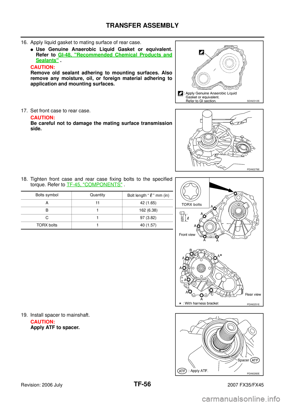
18. Tighten front case and rear case fixing bolts to the specified torque. Refer to TF-45, "
COMPONENTS" .
19. Install spacer to mainshaft. CAUTION:
Apply ATF to spacer.
SDIA2312E
PDIA0279E
Bolts symbol Quantity Bolt length “ ” mm (in)
A 11 42 (1.65)
B 1 162 (6.38)
C 1 97 (3.82)
TORX bolts 1 40 (1.57)
PDIA0251E
PDIA0260E
Page 4261 of 4366

TRANSFER ASSEMBLY TF-57
C E F
G H
I
J
K L
M A
B
TF
Revision: 2006 July 2007 FX35/FX45
20. Install rear oil seal to rear case, using a drift.
CAUTION:
�Do not reuse rear oil seal.
�Apply ATF to rear oil seal.
�When installing, do not incline rear oil seal.
21. Install companion flange while align the matching mark of main- shaft with the mark of companion flange.
22. Tighten self-lock nut to the specified torque, with flange wrench. Refer to TF-45, "
COMPONENTS" .
CAUTION:
Do not reuse self-lock nut.
23. Install mainshaft oil seal until it is flush with end face of front case, using drift.
CAUTION:
�Do not reuse mainshaft oil seal.
�Apply ATF to mainshaft oil seal.
�When installing, do not incline mainshaft oil seal.
24. Install front oil seal until it is flush with end face of front case, using drift.
CAUTION:
�Do not reuse front oil seal.
�Apply ATF to front oil seal.
�When installing, do not incline front oil seal.
25. Apply sealant to threads of drain plug. Then install it to rear case and tighten to the specified torque. Refer to TF-45, "
COMPO-
NENTS" .
Dimension A : 6.7 - 7.3 mm (0.264 - 0.287 in)
Tool number A: ST30720000 (J-25405) B: KV40104830 ( — )
PDIA0281E
SDIA2378E
SDIA2369E
Tool number : ST30720000 (J-25405)
PDIA0282E
Tool number : ST27862000 ( — )
PDIA0287E
Page 4262 of 4366
TF-58
TRANSFER ASSEMBLY
Revision: 2006 July 2007 FX35/FX45
�Use Genuine Silicone RTV or equivalent. Refer to GI-48, "Recommended Chemical Products and
Sealants" .
CAUTION:
Remove old sealant and oil adhering to threads.
26. Set gasket to filler plug. Install it to rear case and tighten to the specified torque. Refer to TF-45, "
COM-
PONENTS" .
CAUTION:
Do not reuse gasket.
Page 4274 of 4366
, install
two balance weight sheets in line with each other as shown in
t")
WT-10
ROAD WHEEL TIRE ASSEMBLY
Revision: 2006 July 2007 FX35/FX45
d. If calculated balance weight value exceeds 50 g (1.76 oz), install
two balance weight sheets in line with each other as shown in
the figure.
CAUTION:
Do not install one balance weight sheet on top of another.
3. Start tire balance machine again.
4. Install drive-in balance weight on inner side of road wheel in the tire balance machine indication position (angle).
CAUTION:
Do not install more than two balance weights.
5. Start tire balance machine. Make sure that inner and outer resid- ual unbalance values are 5 g (0.2 oz) each or below.
6. If either residual unbalance value exceeds 5 g (0.2 oz), repeat installation procedures.
Tire RotationNES000KZ
1. Follow the maintenance schedule for tire rotation service intervals. Refer to MA-7, "Introduction of Peri-
odic Maintenance" .
2. Do not include the spare tire when rotating the tires.
3. When installing the wheel, tighten wheel nuts to the specified torque.
CAUTION:
�When installing wheels, tighten them diagonally by dividing the work two to three times in order
to prevent the wheels from developing any distortion.
�Be careful not to tighten wheel nut at torque exceeding the criteria for preventing strain of disc
rotor.
4. Perform the ID registration, after tire rotation. Refer to WT-20, "
ID Registration Procedure" .
Wheel balance Dynamic (At rim flange) Static (At rim flange)
Maximum allowable
unbalance 5 g (0.2 oz) (one side) 20 g (0.7 oz)
SMA056D
Wheel nuts : 108 N·m (11 kg-m, 80 ft-lb)
Page 4339 of 4366

FRONT WIPER AND WASHER SYSTEM WW-33
C
D E
F
G H
I
J
L
M A
B
WW
Revision: 2006 July 2007 FX35/FX45
Removal and Installation of Front Wiper Arms, Adjustment of Wiper Arms Stop
Location
NKS004OX
REMOVAL
1. Turn front wiper switch ON to operate wiper motor, and then turn front wiper switch OFF (auto stop).
2. Open hood, remove front wiper arm caps, and remove washer tube from washer tube joint.
3. Remove front wiper arm nuts.
4. Raise front wiper arms, and remove front wiper arms from the vehicle.
INSTALLATION
1. Clean up the pivot area as shown in the figure. This will reduce possibility of front wiper arm nuts looseness.
2. Prior to front wiper arms installation, turn front wiper switch ON to operate wiper motor, and then turn front wiper switch OFF
(auto stop).
3. Install washer tube to washer tube joint.
4. Lift the blade up and then set it down onto windshield glass sur- face to set the blade center to clearance “L1” & “L2” immedi-
ately.
5. Tighten front wiper arm nuts to specified torque.
6. Spray washer fluid. Turn on wiper switch ON to operate wiper motor, and then turn front wiper switch OFF (auto stop).
7. Make sure that wiper blades stop within clearance “L1” & “L2”.
8. Install front wiper arm caps.
Removal and Installation of Front Wiper Drive Assembly NKS004OY
REMOVAL
1. Remove front wiper arms. Refer to WW-33, "REMOVAL" .
2. Remove cowl top cover. Refer to EI-23, "
COWL TOP" .
3. Remove washer tube.
4. Disconnect wiper motor connector.
5. Remove front wiper drive assembly mounting bolts, and remove front wiper drive assembly from the vehicle.
SEL024J
Front wiper arm nuts : 23.6 N·m (2.4 kg-m, 17 ft-lb)
Clearance “L1” : 49.4 ± 5.0 mm (1.945 ± 0.2 in)
Clearance “L2” : 43.0 ± 5.0 mm (1.693 ± 0.2 in)
PKIA9951E
SKIA5070E
Page 4357 of 4366

REAR WIPER AND WASHER SYSTEM WW-51
C
D E
F
G H
I
J
L
M A
B
WW
Revision: 2006 July 2007 FX35/FX45
Removal and Installation of Rear Wiper Arm, Adjustment of Wiper Arms Stop
Location
NKS004P1
REMOVAL
1. Turn rear wiper switch ON to operate wiper motor, then turn rear wiper switch OFF (auto stop).
2. Remove rear wiper arm cap, and remove rear wiper arm nut.
3. Remove rear wiper arm from the vehicle.
INSTALLATION
1. Clean up the pivot area as shown in the figure. This will reduce possibility of rear wiper arm nuts looseness.
2. Prior to rear wiper arms installation, turn rear wiper switch ON to operate wiper motor, and then turn rear wiper switch OFF (auto
stop).
3. Lift the blade up and then set it down onto back door window glass surface to set the blade center to lowest heat wire immedi-
ately.
4. Tighten rear wiper arm nuts to specified torque.
5. Spray washer fluid. Turn on rear wiper switch ON to operate wiper motor, and then turn rear wiper switch OFF (auto stop).
6. Ensure that wiper blade stop within the following range.
7. Install rear wiper arm cap.
Removal and Installation of Rear Wiper BladeNKS004P2
REMOVAL
1. Remove rear wiper arm. Refer to WW-51, "REMOVAL" .
2. Turn rear wiper blade 90 degrees against rear wiper arm, and pull it out downward for removal.
CAUTION:
Replace rear wiper blade as rear wiper blade assembly.
SKIA0082J
Rear wiper arm nut : 8.8 N·m (0.90 kg-m, 78 in-lb)
Lowest heat wire : ± 3.75 mm ( ± 0.148 in)
PKID0496E
SKIA6169E
Page 4365 of 4366
HORN
WW-59
C
D E
F
G H
I
J
L
M A
B
WW
Revision: 2006 July 2007 FX35/FX45
Removal and InstallationNKS0033X
REMOVAL
1. Remove front grille. Refer to EI-22, "FRONT GRILLE" .
2. Disconnect all horn connectors.
3. Remove horn mounting bolt and remove horn from vehicle.
INSTALLATION
Installation is the reverse order of removal.
�Tighten horn bolt to specified torque.
SKIA5093E
Horn mounting bolt : 5.8 N·m (0.59 kg-m, 51 in-lb)