Page 1163 of 1226
308-03-73 Manual Transmission/Transaxle 308-03-73
INSTALLATION
27. Attach the power steering high-pressure 30. Tighten the engine rear mount outer
/ line retaining bracket to the transaxle. retaining nuts. I
28. Install the transaxle upper retaining bolts. 31. Tighten the engine rear mount center
retaining nut.
29. Install the engine wiring harness bracket.
32. Install the battery tray support bracket.
33. Install the front wheels and tires.
For additional information, refer to: Wheel
and Tire
(204-04 Wheels and Tires,
Removal and Installation).
- -- -- --
2006.0 Fiesta 1212006 G453417en
procarmanuals.com
Page 1177 of 1226
309-00-1 Exhaust System 309-00-1
SECTION 309-00 Exhaust System
VEHICLE APPLICATION:2006.0 Fiesta
CONTENTS PAGE
SPECIFICATIONS
Specifications ........................................................................\
.............................................. 309-00-2
DESCRIPTION AND
OPERATION
Exhaust System ........................................................................\
.......................................... 309-00-4
Exhaust system
- 1.31, 1.41 and 1.61 petrol engines and 1.41 diesel engines ...................... 309-00-4
REMOVAL AND INSTALLATION
Catalytic Converter - 2.OL Duratec-HE (M14) ................................................................... 309-00-6
Exhaust Flexible Pipe
- 2.OL Duratec-HE (M14) ............................................................... 309-00-8
procarmanuals.com
Page 1178 of 1226

309-00-2 Exhaust System 309-00-2
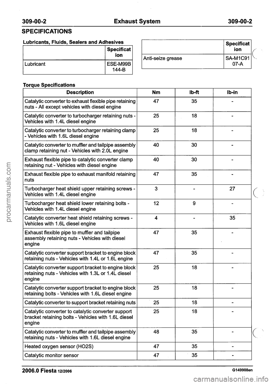
SPECIFICATIONS
Lubricants. Fluids. Sealers and Adhesives I Specificat I
Specificat
I ion I
I ion I/- ,
Anti-seize grease I SA-MI C91 I 'c-
Lubricant
Torque Specifications
I Description I Nm I Ibf I Ib-in I
Catalytic converter to exhaust flexible pipe retaining
nuts
- All except vehicles with diesel engine
Catalytic converter to turbocharger retaining nuts
-
Vehicles with I .4L diesel engine
Catalytic converter to turbocharger retaining clamp
- Vehicles with 1.6L diesel engine
Catalytic converter to muffler and tailpipe assembly
clamp retaining nut
- Vehicles with 2.OL engine
Exhaust flexible pipe to catalytic converter clamp
retaining nut
- Vehicles with diesel engine
Exhaust flexible pipe to exhaust manifold retaining
1 nuts
Turbocharger heat shield upper retaining screws
-
Vehicles with I .4L diesel engine
Turbocharger heat shield lower retaining bolts
-
Vehicles with I .4L diesel engine
Catalytic converter heat shield retaining screws
-
Vehicles with I .6L diesel engine
Exhaust flexible pipe to muffler and tailpipe
assembly retaining nuts
- Vehicles with diesel
engine
Catalytic converter support bracket to engine block
retaining nuts
- Vehicles with 1.4L or 1.6L engine
Catalytic converter support bracket to engine block
retaining nuts
- Vehicles with 1.3L or 1.4L diesel
engine
Catalytic converter support bracket to engine block retaining bolts
- Vehicles with I .6L diesel engine
I Catalytic converter to support bracket retaining nuts I 25 I 18 I - 1
Catalytic converter to catalytic converter support
bracket retaining bolts
- Vehicles with 1.6L diesel
engine
Catalytic converter to muffler and tailpipe assembly
retaining nuts
- Vehicles with 1.6L diesel engine
I Heated oxygen sensor (H02S) I 47 I 35 I - I
I Catalytic monitor sensor I 47 I 35 I - I
2006.0 Fiesta 1212006 G149908en
procarmanuals.com
Page 1179 of 1226
309-00-3 Exhaust System 309-00-3
SPECIFICATIONS
2006.0 Fiesta 1212006 Gl49908en
Description
Exhaust flexible pipe to front muffler pipe heat shield
retaining bolts
- Vehicles with 1.6L engine
Exhaust flexible pipe clamp retaining nut
- Vehicles
with diesel engine
Rear muffler clamp retaining nuts
- All except
vehicles with diesel engine
Nm
8
47
47
lb-ft
-
35
35
l b-i n
71
-
-
procarmanuals.com
Page 1180 of 1226
309-00-4 Exhaust System 309-00-4
DESCRIPTION AND OPERATION
Exhaust System
Exhaust system - 1.31, 1.41 and 1.61 petrol engines and 1.41 diesel engines
Description Item Description
2 Servicing clamp
3 Front muffler
(
I D 1 1.41 DuraTorq TDCi I
I 1 I Flexible pipe I
2006.0 Fiesta 1212006 GI 67275en
procarmanuals.com
Page 1189 of 1226
31 0-00-3 Fuel System - General Information 31 0-00-3
GENERAL PROCEDURES
/'
Fuel System Pressure Release(23 420 0)
i
Release
I. WARNINGS:
ADO not smoke or carry lighted tobacco or
open flame of any type when working on or
near any fuel related components. Highly
flammable vapors are always present and
may ignite. Failure to follow these
instructions may result in personal injury.
A~he fuel system remains pressurized for
a long time after the ignition is switched off.
The fuel pressure must be released before
attempting any repairs. Failure to follow this
instruction may result in personal injury.
Remove the fuel pump fuse.
2. Start the engine and allow to idle until the
engine stalls.
3. Crank the engine for approximately five
seconds to make sure the fuel injection
supply manifold pressure has been released.
,1 4. Install the fuel pump fuse.
2006.0 Fiesta 1212006 GI 81 91 en
procarmanuals.com
Page 1197 of 1226

31 0-00-1 I Fuel System - General Information 31 0-00-1 1
GENERAL PROCEDURES
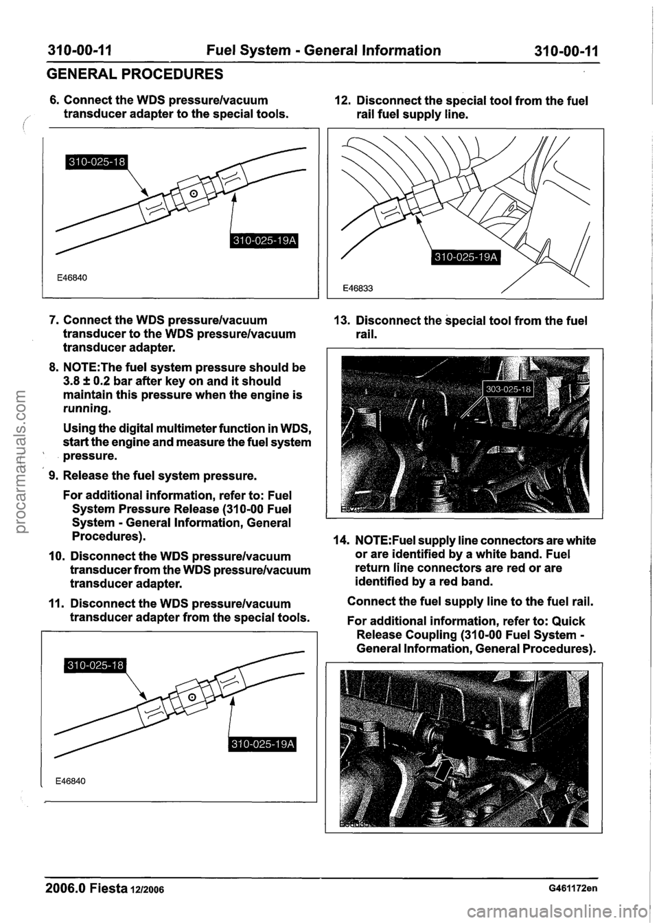
6. Connect the WDS pressurelvacuum 12. Disconnect the special tool from the fuel
/' transducer adapter to the special tools.
rail fuel supply line.
7. Connect the WDS pressurelvacuum
transducer to the WDS pressurelvacuum
transducer adapter.
8. N0TE:The fuel system pressure should be
3.8 f 0.2 bar after key on and it should
maintain this pressure when the engine is
running.
Using the digital multimeter function in WDS,
start the engine and measure the fuel system
pressure.
(,
9. Release the fuel system pressure.
For additional information, refer to: Fuel
System Pressure Release
(31 0-00 Fuel
System
- General Information, General
Procedures).
10. Disconnect the WDS pressurelvacuum
transducer from the WDS pressurelvacuum
transducer adapter.
11. Disconnect the WDS pressurelvacuum
transducer adapter from the special tools.
2006.0 Fiesta 1212006
13. Disconnect the special tool from the fuel
rail.
14. N0TE:Fuel supply line connectors are white
or are identified by a white band. Fuel
return line connectors are red or are
identified by a red band.
Connect the fuel supply line to the fuel rail.
For additional information, refer to: Quick
Release Coupling
(310-00 Fuel System -
General Information, General Procedures).
procarmanuals.com
Page 1200 of 1226
31 0-01 -2 Fuel Tank and Lines 31 0-01 -2
SPECIFICATIONS
Torque Specifications
Description
Nm Ib-ft I b-in I/
Fuel tank support strap retaining bolts I 25 I 18 I -
Fuel tank filler pipe retaining bolts I 9 I - I 80 I
Fuel pump module locking ring - All except vehicles
with diesel engine
Fuel level sensor locking ring
- Vehicles with diesel
engine
Floor panel crossmember
I 4 I - I 35 I
2006.0 Fiesta 1212006 GI 48228en
procarmanuals.com