2007 FORD FIESTA timing
[x] Cancel search: timingPage 995 of 1226

Automatic Transmission/Transaxle -
Vehicles With: 4Speed Automatic
307-01 -35 Transmission (AW81-40) 307-01 -35
DESCRIPTION AND OPERATION
Engine speed
1 The engine speed is detected by the crankshaft
position (CKP) sensor and passed on to the PCM.
The engine speed is transmitted from the PCM via
the CAN
databus to the transmission control unit.
The transmission control unit uses this signal for:
Torque reduction during gearshifts,
Pressure control during gearshifts.
Engine load
The PCM determines a load signal which is
transmitted via the CAN
databus to the
transmission control unit.
The transmission control unit uses this signal for:
Torque reduction during gearshifts,
Pressure control during gearshifts,
Shift timing adaptation during upshifts,
Shift timing adaptation during shifts from 3rd to
4th gear,
Hill climb mode,
( ' Hill descent mode. ' ,
Torque reduction request signal
Before performing a gearshift, the transmission
control unit sends a signal via the CAN
databus to
the PCM requesting a torque reduction.
The PCM then reduces the engine torque, ensuring
that the gearshift is as smooth and judder-free as
possible.
Brake signal
The PCM receives a signal from the stoplamp
switch when the brake pedal is depressed.
This signal is transmitted via the CAN
databus to
the transmission control unit.
The transmission control unit uses this signal for:
Gearshift control,
Engagement of the TCC
Accelerator pedal position
The PCM receives the current accelerator pedal
position signal from the Accelerator Pedal Position
(APP) sensor.
This signal is transmitted via the CAN
databus to
the transmission control unit.
The transmission control unit uses this signal for:
Controlling the main line pressure,
Gearshift control,
Engagement of the TCC,
Shift timing adaptation during upshifts,
Shift timing adaptation during shifts from 3rd to
4th gear,
Shift timing adaptation during shifts from 4th to
3rd gear,
Avoidance of gearshift judder during
engagement of a transmission range,
Torque reduction when pulling away.
Coolant temperature
The coolant temperature is detected by the Engine
Coolant Temperature (ECT) sensor and passed
on to the PCM.
This signal is transmitted via the CAN
databus to
the transmission control unit.
The transmission control unit uses this signal for:
Cold start mode,
Engagement of the TCC
Selector lever position
The transmission control unit transmits the selector
lever position to the instrument cluster.
The instrument cluster uses the signal to send a
request for a warning tone to the GEM when the
selector lever is not in position "P" and the driver's
door is opened.
-
2006.0 Fiesta 1212006 G380530en
procarmanuals.com
Page 997 of 1226

Automatic TransmissionlTransaxle -
Vehicles With: 4-Speed Automatic
307-01 -37 Transmission
(AW81-40) 307-01 -37
DESCRIPTION AND OPERATION
Sensors
OSS sensor
TSS sensor
The TSS sensor is an inductive pickup.
It measures the transmission input speed via the
outer plate carrier of the
3rdl4th gear clutch and
sends the signal to the transmission control unit.
The transmission control unit uses this signal for:
Torque reduction during gearshifts,
Pressure control during gearshifts,
Shift timing adaptation during upshifts,
Shift timing adaptation during shifts from 3rd to
4th gear,
Shift timing adaptation during shifts from 4th to
3rd gear,
Avoidance of gearshift judder during
engagement of a transmission range,
Torque reduction when pulling away.
Consequences of signal failure:
No TCC,
no torque reduction,
no shift timing adaptation,
no 4th gear. The
OSS sensor is a Hall sensor.
It is mechanically connected via a gear to the input
wheel of the differential assembly.
It measures the vehicle speed via the input wheel
of the differential assembly and sends the signal
to the transmission control unit.
The transmission control unit uses this signal for:
Gearshift control,
Engagement of the TCC,
Torque reduction during gearshifts,
Pressure control during gearshifts,
Shift timing adaptation during upshifts,
Shift timing adaptation during shifts from 3rd to
4th gear,
Shift timing adaptation during shifts from 4th to
3rd gear,
Reverse gear safety strategy,
Avoidance of gearshift judder during
engagement of a transmission range,
Torque reduction when pulling away,
Hill climb mode,
Hill descent mode.
2006.0 Fiesta 1212006 G380530en
procarmanuals.com
Page 998 of 1226

Automatic Transmission/Transaxle -
Vehicles With: 4Speed Automatic
307-01 -38 Transmission (AW81-40) 307-01 -38
DESCRIPTION AND OPERATION
Consequences of signal failure:
NoTCC,
no torque reduction, no shift timing adaptation,
no 4th
gear.
TR sensor
The TR sensor serves to signal the currently
selected transmission range to the transmission
control unit.
It is a switch which transmits the selected
transmission range directly to the transmission
control unit.
In addition, the starter inhibit relay is actuated by
the PCM via the TR sensor when the selector lever
is in the positions "P" or
N.
In selector lever position "R the backup lamp relay
is also actuated via the TR sensor.
The transmission control unit uses this signal for:
Controlling the main line pressure,
Gearshift control,
Engagement of the TCC,
Shift timing adaptation during upshifts,
Shift timing adaptation during shifts from 3rd to
4th gear,
Shift timing adaptation during shifts from 4th to
3rd gear,
Reverse gear safety strategy,
Avoidance of gearshift judder during
engagement of a transmission range,
Torque reduction when pulling away.
Consequences of signal failure:
NoTCC,
no shift timing adaptation.
2006.0 Fiesta 1212006 G380530en
procarmanuals.com
Page 999 of 1226

Automatic Transmission/Transaxle -
Vehicles With: 4-Speed Automatic
307-01 -39 Transmission (AW81-40) 307-01 -39
DESCRIPTION AND OPERATION
TFT sensor Overdrive switch
The TFT sensor is located in the oil pan on the
main control body and is part of the transmission
wiring harness.
It measures the current transmission fluid
temperature and sends the signal to the
transmission control unit.
The transmission control unit uses this signal for:
Cold start mode,
Engagement of the TCC,
Shift timing adaptation during upshifts,
' , Shift timing adaptation during shifts from 3rd to
4th gear,
Shift timing adaptation during shifts from 4th to
3rd gear,
Overheating protection mode.
Consequences of signal failure:
NoTCC,
no shift timing adaptation,
no 4th gear. The overdrive switch
is located on the selector
lever.
It allows the driver to suppress or enable gearshifts
into 4th gear when
"D" is selected.
The signal from the overdrive switch is transmitted
to the transmission control unit.
When gearshifts into 4th gear are suppressed, the
transmission control unit sends a corresponding
signal via the CAN
databus to the instrument
cluster. The instrument cluster then actuates the
overdrive indicator lamp.
Consequences of signal failure:
no suppression of gearshifts into 4th gear.
2006.0 Fiesta 1212006 G380530en
procarmanuals.com
Page 1001 of 1226
Automatic Transmission/Transaxle -
Vehicles With: 4-Speed Automatic
307-01
-41 Transmission (AW81-40) 307-01 -41
DESCRIPTION AND OPERATION
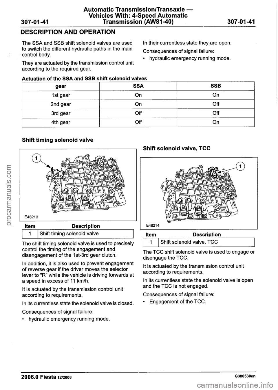
The SSA and SSB shift solenoid valves are used In
their currentless state they are open.
to switch the different hydraulic paths in the main
Consequences of signal failure: control body. hydraulic emergency running mode.
They are actuated by the transmission control unit
according to the required gear.
Actuation of the SSA and SSB shift solenoid valves
Shift timing solenoid valve
gear
I st gear
2nd gear
3rd gear
4th gear
kern Descri~tion
I 1 I Shift timing solenoid valve I
SSA On
On Off
Off
The shift timing solenoid valve is used to precisely SSB
On Off
Off
On
control the timing of the engagement and
disengagement of the
I st3rd gear clutch.
In addition, it is also used to prevent engagement
of reverse gear if the driver moves the selector
lever to "R" while the vehicle is driving forwards at
a speed in excess of
11 kmlh.
It is actuated by the transmission control unit
according to requirements.
In its currentless state the solenoid valve is closed.
Consequences of signal failure: hydraulic emergency running mode.
Shift solenoid valve, TCC
Item Description
I 1 I Shift solenoid valve, TCC I
The TCC shift solenoid valve is used to engage or
disengage the TCC.
It is actuated by the transmission control unit
according to requirements.
In its currentless state the solenoid valve is open
and the TCC is not engaged.
Consequences of signal failure:
Engagement of the TCC.
2006.0 Fiesta 1212006 G380530en
procarmanuals.com
Page 1006 of 1226
Automatic Transmission/Transaxle -
Vehicles With: 4Speed Automatic
307-01 -46 Transmission
(AW81-40) 307101 -46
DIAGNOSIS AND TESTING
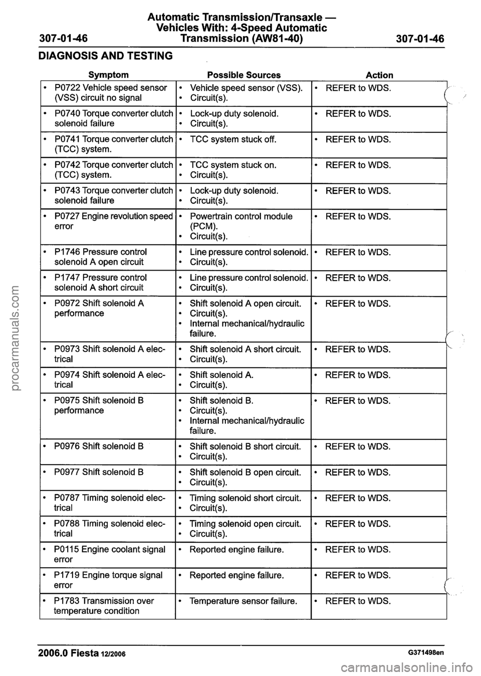
Symptom Possible Sources Action
PO722 Vehicle speed sensor Vehicle speed sensor (VSS).
1 (vSS) circuit no signal I circuit(+
REFER to WDS.
PO740 Torque converter clutch Lock-up duty solenoid.
solenoid failure
I ~ircuit(s).
REFER to WDS.
REFER to WDS.
PO741 Torque converter clutch
1 (TCC) system.
PO742 Torque converter clutch TCC system stuck on.
I circuit(s).
TCC system stuck off.
REFER to WDS.
PO743 Torque converter clutch Lock-up duty solenoid.
solenoid failure
I circuit(s).
REFER to WDS.
REFER to WDS.
PO727 Engine revolution speed
error
PI 746 Pressure control
I solenoid A open circuit
Powertrain control module
(PCM).
Circuit(s).
I
Line pressure control solenoid.
Circuit(s).
REFER to WDS.
PI 747 Pressure control
solenoid
A short circuit
Line pressure control solenoid.
Circuit(s).
REFER to WDS.
PO972 Shift solenoid A
performance Shift solenoid
A open
circuit.
Circuit(s).
Internal mechanical/hydraulic
failure.
REFER to WDS.
REFER to WDS.
PO974 Shift solenoid A elec- Shift solenoid A.
trical I circuit(!+
PO973 Shift solenoid A elec-
trical
REFER to WDS. Shift solenoid A short circuit.
Circuit(s).
PO975 Shift solenoid B
performance Shift solenoid
B.
Circuit(s).
Internal mechanical/hydraulic
failure.
REFER
to WDS.
PO976 Shift solenoid B Shift solenoid B short circuit.
Circuit(s).
REFER to WDS.
PO977 Shift solenoid B Shift solenoid B open circuit.
Circuit(s).
REFER to WDS.
PO787 Timing solenoid elec- Timing solenoid short circuit.
trical I circuit(s).
REFER to WDS.
REFER to WDS. PO788 Timing solenoid elec-
trical
-- - -
Timing solenoid open circuit.
Circuit(s).
REFER to WDS. PO1 15 Engine coolant signal
error Reported engine failure.
REFER to WDS. I PI 71 9 Engine torque signal
error Reported engine failure.
REFER to WDS. PI 783 Transmission over
temperature condition
2006.0 Fiesta 12/2006 G371498en
Temperature sensor failure.
procarmanuals.com
Page 1009 of 1226
Automatic Transmission/Transaxle -
Vehicles With: 4-Speed Automatic
307-01 49 Transmission (AW81-40) 307-01 -49
DIAGNOSIS AND TESTING
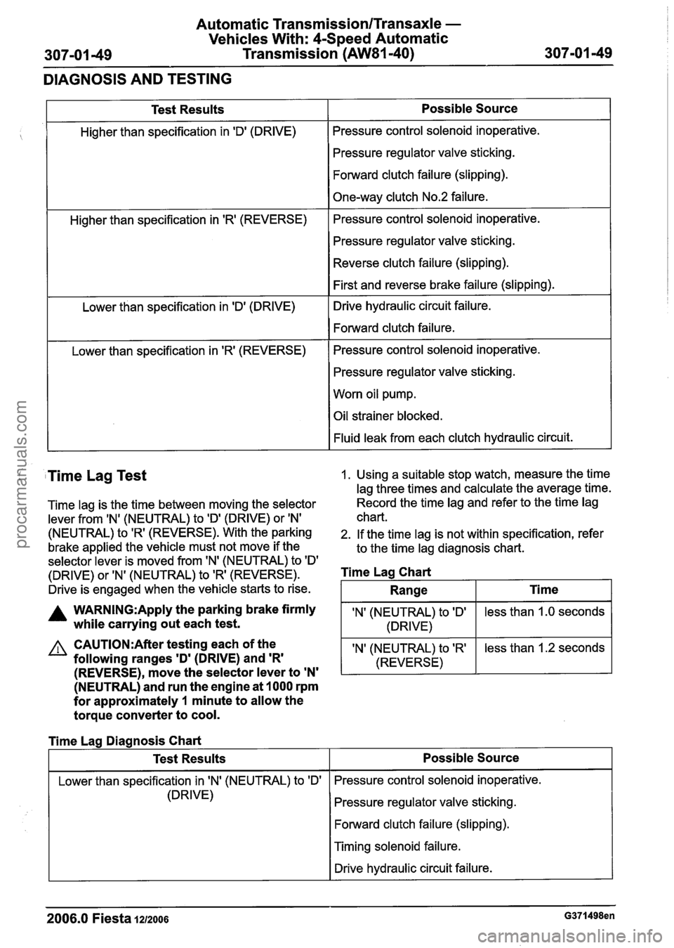
Test Results
Higher than specification in 'Dl (DRIVE)
Higher than specification in
'R' (REVERSE)
Lower than specification in 'D' (DRIVE)
Lower than specification in
'R' (REVERSE)
Possible Source
Pressure control solenoid inoperative.
Pressure regulator valve sticking.
Forward clutch failure (slipping).
One-way clutch No.2 failure.
Pressure control solenoid inoperative.
Pressure regulator valve sticking.
Reverse clutch failure (slipping).
First and reverse brake failure (slipping).
Drive hydraulic circuit failure.
Forward clutch failure.
Pressure control solenoid inoperative.
Pressure regulator valve sticking.
Worn oil pump.
Oil strainer blocked.
Fluid leak from each clutch hydraulic circuit.
( Time Lag Test 1. Using a suitable stop watch, measure the time
lag three times and calculate the average time.
Time lag is the time between moving the selector Record the
time lag and refer to the time lag
lever from
IN' (NEUTRAL) to ID' (DRIVE) or IN' chart.
(NEUTRAL) to 'R' (REVERSE). With the parking 2. If the time lag is not within specification, refer
brake applied the vehicle must not move if the
to the time lag diagnosis chart.
selector lever is moved from 'N' (NEUTRAL) to
ID'
(DRIVE) or 'N' (NEUTRAL) to 'R' (REVERSE). Time Lag Chart
Drive is engaged when the vehicle starts to rise.
A WARN1NG:Apply the parking brake firmly IN' (NEUTRAL) to ID' while carrying out each test. 1 (DRIVE)
(NEUTRAL) and run the engine at 1000 rpm
for approximately
1 minute to allow the
torque converter to cool.
less than 1.0 seconds
CAUTI0N:After testing each of the
following ranges
'D' (DRIVE) and 'R'
Range
I Lower than specification in IN' (NEUTRAL) to 'Dl I Pressure control solenoid inoperative.
Ti me
(REVERSE), move the selector lever to 'N'
'N' (NEUTRAL) to 'R'
(REVERSE)
Time Lag Diagnosis Chart
(DRIVE) less
than 1.2 seconds
Test Results
Pressure regulator valve sticking.
Forward clutch failure (slipping).
Possible Source
I Timing solenoid failure.
I I Drive hydraulic circuit failure. I
2006.0 Fiesta IZIZOO~ G371498en
procarmanuals.com
Page 1224 of 1226
31 0-02B-2 Acceleration Control - 2.OL Duratec-HE (M14) 31 0-02B-2
DESCRIPTION AND OPERATION
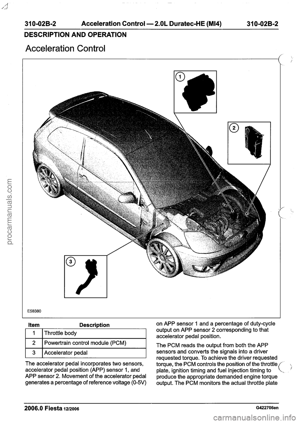
Acceleration Control
Description on APP sensor 1 and a percentage of duty-cycle
Throttle body output on
APP sensor
2 corresponding to that
accelerator pedal position.
Powertrain control module (PCM)
The PCM reads the output from both the APP
3 Accelerator pedal T sensors requested and torque. converts To achieve the signals the driver into a requested driver
The accelerator pedal incorporates two sensors,
torque, the PCM controls the position of the throttle(
accelerator pedal position (APP) sensor
1, and
plate, ignition timing and fuel injection timing to .
APP sensor 2. Movement of the accelerator pedal
produce the appropriate demanded engine torque
generates a
percentage of reference voltage (0-5V) output. The PCM monitors the actual throttle plate
2006.0 Fiesta 1212006 G422706en
procarmanuals.com