2007 FORD FIESTA timing
[x] Cancel search: timingPage 927 of 1226

303-1 4-3 Electronic Engine Controls 303-1 4-3
SPECIFICATIONS
control module (PCM) retaining nuts
and retaining bolts
Torque
Specifications
- vehicles with 1.6L Duratorq-TDCi (DV) Diesel engine
I Camshaft position (cMP) sensor retaining bolt I 5 I - I 44 I
lb-in
Timing belt upper cover retaining bolts
Timing belt lower cover retaining bolts
I Crankshaft position (CKP) sensor retaining bolt I 8 I - I 71 I
Ib-ft Description
I Crankshaft pulley retaining bolt I a I - I - I
Nm
4
6
I For additional information, refer to: Crankshaft Position (CKP) Sensor - 1.6L Duratorq-TDCi (DV) Diesel (303-14 Electronic Engine I
I Controls, Removal and Installation). I
-
-
Torque Specifications - vehicles with 2.OL Duratec-HE (M14) eng 35
53
I Description I Nm
ine
I Powertrain control module
(PCM) retaining bolts I 10 I - I 89 I
I PCM mounting bracket retaining bolts I 25 I 18 I - I
I Knock sensor (KS) retaining bolt I 20 I 15 I - I
I Crankshaft position (CKP) sensor retaining bolt I 7
'1 Camshaft position (CMP) sensor retaining bolt I 6
I Ignition coil pack retaining bolts I 6 I - I 53 I
I Exhaust manifold heatshield retaining bolts I 10 I - I 89 I
2006.0 Fiesta 1212006 GI 48226en
-- -
Heated oxygen sensor (H02S)
Catalyst monitor sensor (CMS) 47
47
35
35
-
-
procarmanuals.com
Page 936 of 1226

303-1 4-1 2 Electronic Engine Controls 303-1 4-1 2
DESCRIPTION AND OPERATION
Powertrain control module (PCM) The KS detects engine vibrations caused by knock
and produces an output voltage signal in proportion
, to the knock. The PCM uses the voltage signal to(
control knock by retarding the ignition timing.
The powertrain control module is located within the
engine compartment below the battery and is
secured to the left-hand chassis rail by means of
a mounting bracket. On right-hand drive vehicles
the PCM is protected by a security shield which is
secured to the retaining bracket by a shear-head
bolt. In order to disconnect the PCM electrical
connectors it is necessary to remove the security
shield.
The PCM monitors and processes the signals from
the sensors and compares these with stored
parameters. The PCM uses this information to
calculate the output signals to the actuators.
Communications between the PCM and other
control units (for example, the stability assist and
the instrument cluster) including the DLC for
diagnosis of the system, take place on the
controller area network (CAN).
Intake manifold tuning valve solenoid
The solenoid for the intake manifold tuning system
is located on the transmission side of the cylinder
head.
Vacuum is supplied by a central vacuum
connection from the intake manifold.
The solenoid for the intake manifold tuning system
is supplied with either the maximum voltage or zero
voltage,
i.e. the valves are either fully open or fully
closed.
Actuation depends on the engine speed and the
engine load.
Diagnosis can be carried out through the DLC
using the Worldwide Diagnostic System (WDS)
BPP switch
diagnostic equipment.
Knock sensor (KS)
The BPP switch and the stoplamp switch are tt(r located on the pedal box and provide the PCM with
the information that the brake pedal has been
pressed and that the vehicle is therefore being
The knock sensor is located on the cylinder block decelerated.
between cylinders
2 and 3.
2006.0 Fiesta 1212006 G422229en
procarmanuals.com
Page 956 of 1226

303-1 4-32 Electronic Engine Controls 303-1 4-32
REMOVAL AND INSTALLATION
Crankshaft Position (CKP) Sensor
General Equipment A~i~hten the M6 x 18 mm bolt finger-tight L,. '
2. Remove the splash shield
I ~olt, ~6 x 18 mm
CKP alignment tool
3. CAUTIONS: only.
Rotate the crankshaft pulley clockwise until
A0nly turn the crankshaft pulley in the
normal direction of rotation. the
crankshaft pulley timing bolt,
M6 x 18
I. Raise and support the vehicle.
mm can be installed through the crankshaft
For additional information, refer to: Lifting pulley
timing hole into the engine front cover.
(1 00-02, Description and Operation).
4. Remove the components in the order
indicated in the following
illustration(s) and
2006.0 Fiesta 1212006 ~423211 en
procarmanuals.com
Page 972 of 1226
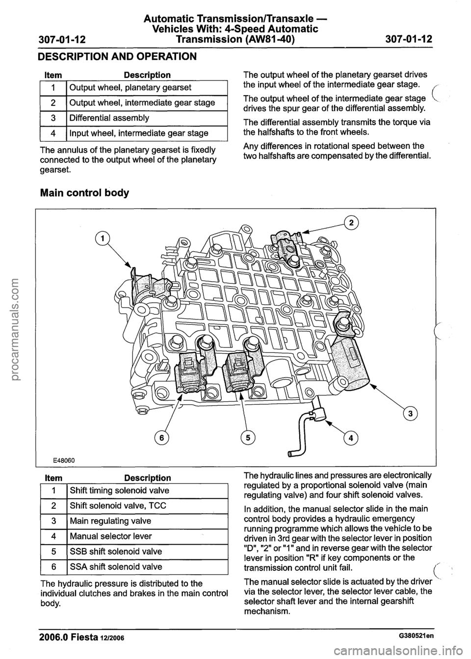
Automatic Transmission/Transaxle -
Vehicles With: 4-Speed Automatic
307-01 -1 2 Transmission (AW81-40) 307-01 -1 2 --
DESCRIPTION AND OPERATION
Item Description The output wheel of the planetary gearset drives
I 1 I Output wheel, planetary gearset
2
I I 1
The annulus of the planetary gearset is fixedly Any differences in rotational speed between the
connected to the output
wheel of the planetary two halfshafts are compensated by the differential.
gearset.
the input wheel of the intermediate gear stage.
3
4
Main control body
Output wheel, intermediate gear stage
Item Descri~tion The hydraulic lines and pressures are electronically
The output
wheel of
the intermediate gear stage [<.
drives the spur gear of the differential assembly.
Differential assembly
Input wheel, intermediate gear stage The
differential assembly transmits the torque
via
the halfshafts to the front wheels.
In addition, the manual selector slide in the main
control body provides a hydraulic emergency
running programme which
allows the vehicle to be
Manual selector lever driven in 3rd aear with the selector lever in position
.
1
Shift timing solenoid valve
5
2006.0 Fiesta 1212006 ~380521 en
regulated by a proportional solenoid valve (main
regulating valve) and four shift solenoid valves.
1 6 1 SSA shift solenoid valve
SSB
shift solenoid valve
transmission control unit-fail. -
"D", "2" or "ll'and in reverse gear with the selector
lever in position "R if key components or the
The hydraulic pressure is distributed to the The
manual selector slide is actuated by the driver
individual clutches and brakes in the main control via the selector lever, the selector lever cable, the
body. selector shaft lever and the internal gearshift
mechanism.
procarmanuals.com
Page 990 of 1226

Automatic Transmission/Transaxle -
Vehicles With: 4-Speed Automatic
307-01 -30 Transmission (AW81-40) 307-01 -30
DESCRIPTION AND OPERATION
The transmission control unit can be diagnosed
with WDS via the DLC.
Gearshift strategies
Gearshift control
I A I Accelerator pedal position I
I B I vehicle speed 1
The current ratio is selected by the transmission
control unit either in accordance with the
requirements for low fuel consumption or in order
to meet the required driving performance.
The gearshift timing is selected in accordance with
a gearshift map which is programmed into the
control unit as a function of the accelerator pedal
position and the vehicle speed.
For kick-down (accelerator pedal pressed down at
least
95 %) the next lowest gear is selected, as
long as the engine speed allows it. All gearshift
timings are set by the transmission control unit to
the upper shift characteristic. The driver can feel the
kickdown point
in the
accelerator pedal as a slight increase in resistance
to the operation of the pedal.
This is influenced by the following variables:
accelerator pedal position and actuation,
vehicle speed,
brake pedal position,
selector lever position.
The following are actuated:
SSA shift solenoid valve,
SSB shift solenoid valve.
Hill climb mode
When the vehicle is in hill climb mode or towing a
trailer, the transmission control delays gearshifts
to prevent frequent shifting back and forth between
the gears.
2006.0 Fiesta 1u2oos
procarmanuals.com
Page 991 of 1226

Automatic TransmissionlTransaxle -
Vehicles With: 4-Speed Automatic
307-01 -31 Transmission (AW81-40) 307-01 -31
DESCRIPTION AND OPERATION
The transmission control unit determines hill climb
mode or trailer operation from the change in throttle
; valve position supplied by the PCM in relation to
the acceleration of the vehicle.
Depending on the driving resistance, the
transmission control unit chooses between two
gearshift maps which have been specially
programmed for this purpose and in which the shift
timings are again chosen as a function of the
accelerator pedal position and the vehicle speed..
Hill descent mode
The hill descent mode is used to take better
advantage of engine braking during hill descents.
A 'hill descent' situation is recognised by the
transmission control unit if the vehicle is
accelerating without operation of the accelerator
pedal.
If in addition the brake is also depressed then the
transmission control unit automatically shifts back
from 4th into 3rd gear.
( ' Cold start mode
In order to reach operating temperature as quickly
as possible under low ambient temperatures,
gearshifts into 4th gear and engagement of the
torque converter clutch (TCC) are suppressed if
one of the following conditions is met:
Transmission fluid temperature below +20 "C
Coolant temperature below - 40°C
The following are actuated: SSA shift solenoid valve,
SSB shift solenoid valve,
Shift solenoid valve, TCC.
Overheating protection mode
The overheating protection mode serves to protect
the transmission against overheating and the
serious damage that this can cause.
If the transmission fluid temperature reaches a
temperature of around 135
"C, the transmission
control employs a shift pattern designed to prevent
a further increase in the transmission fluid
temperature. When
the transmission fluid temperature drops
back below approx. 125
"C, the transmission
control exits the overheating protection mode.
The MIL warning lamp is actuated by the
transmission control unit if the transmission fluid
temperature reaches approximately 140
"C.
The MIL warning lamp goes out again when the
transmission fluid temperature drops back to below
around 130
"C.
Main line pressure control
In order to ensure the highest possible efficiency
of the automatic transmission and to limit the power
losses from the fluid pump, the main line pressure
is adapted accordingly by the main regulating valve
as a function of the accelerator pedal position
(driver torque demand) and the selector lever
position.
This is influenced by the following variables:
Accelerator pedal position and actuation
Selector lever position
The following are actuated:
Main 'regulating valve
Engagement of the TCC
The TCC is engaged in 3rd and 4th gear depending
on the current driving situation.
Engagement is controlled in accordance with the
shift map stored in the control unit.
This is influenced by the following variables:
Accelerator pedal position and actuation,
Vehicle speed,
Selector lever position,
Transmission fluid temperature,
Coolant temperature.
The following are actuated:
Shift solenoid valve, TCC.
Torque reduction during gearshifts
In order to improve the quality of gearshifts and to
avoid gearshift judder, the engine torque is reduced
by the PCM in response to a request from the
transmission control unit during gearshifts.
The engine torque is also reduced during
engagement and disengagement of the TCC.
2006.0 Fiesta 1212006 G380530en
procarmanuals.com
Page 992 of 1226

Automatic Transmission/Transaxle -
Vehicles With: 4-Speed Automatic
307-01 -32 Transmission
(AW81-40) 307-01 -32
DESCRIPTION AND OPERATION
This is influenced by the following variables:
Engine speed,
Engine load,
Transmission input speed,
Vehicle speed.
The following are actuated:
PCM (torque reduction request signal via the
CAN databus).
Pressure control during gearshifts
In order to ensure that the engagement of the
clutches and brakes is as judder-free as possible,
the main line pressure is reduced during gearshifts.
This is influenced by the following variables:
Enginespeed,
Engine load,
Transmission input speed,
Vehicle speed.
The following are actuated:
Main regulating valve.
Shift timing adaptation during upshifts
In order to ensure that the engagement of the
clutches and brakes is as judder-free as possible,
the timing of the gearshift processes is monitored
during upshifts.
In the event of any discrepancy from the target
values, the main line pressure is adapted
accordingly during the next gearshift.
The shift timing adaptation during upshifts is only
active at transmission fluid temperatures between
50
"C and 120 "C.
This is influenced by the following variables:
Engine load,
Accelerator pedal position,
Transmission input speed,
Vehicle speed,
Transmission fluid temperature,
Selector lever position.
The following are actuated:
Main regulating valve.
Shift timing adaptation during shifts from
3rd to 4th gear
The shift from 3rd gear into 4th gear is the only
gearshift during which a clutch is disengaged and
a brake is engaged simultaneously.
In order to control the synchronized switching of
the two components as exactly as possible, the
shifl timing solenoid valve is actuated accordingly.
In order to ensure that this particular gearshift is
performed as judder-free as possible throughout
the service life of the transmission, the gearshift is
monitored by the two rotational speed sensors and
the actuation of the shift timing solenoid valve is
adapted accordingly.
The shift timing adaptation for gearshifts from 3rd
gear into 4th gear is only active at transmission
fluid temperatures between 30
"C and 120 "C.
This is influenced by the following variables:
Engine load,
Accelerator pedal position,
Transmission input speed,
Vehicle speed,
Transmission fluid temperature,
Selector lever position.
The following are actuated:
Shift timing solenoid valve.
Shift timing adaptation during shifts from
4th to 3rd gear
The shift from 4th gear into 3rd gear is the only
gearshift during which a brake is disengaged and
a clutch is engaged simultaneously.
In order to control the engagement of the clutch as
precisely as possible, the main regulating valve is
actuated accordingly in order to build up the
actuating pressure at exactly the right time.
In order to ensure that this particular gearshift is
performed as judder-free as possible throughout
the service life of the transmission, the gearshift is
monitored by the two rotational speed sensors and
the actuation of the main regulating valve is
adapted accordingly.
The shift timing adaptation for gearshifts from 4th
-
gear into 3rd gear is only active at transmission (
fluid temperatures between 20 "C and 120 "C. .
2006.0 Fiesta 1212006 G380530en
procarmanuals.com
Page 993 of 1226

Automatic Transmission/Transaxle -
Vehicles With: 4Speed Automatic
307-01 -33 Transmission (AW81-40) 307-01 -33
DESCRIPTION AND OPERATION
This is influenced by the following variables: Vehicle
speed,
Engine load, Transmission fluid temperature.
Accelerator pedal position, The following are actuated:
Transmission input speed, SSA shift solenoid valve,
Vehicle speed,
Transmission fluid temperature,
Selector lever position.
The
following are actuated:
Main
regulating valve.
Reverse gear safety strategy
SSB shift solenoid valve.
Torque reduction when pulling away
In order to protect the clutches against excessively
high torque when pulling away, the PCM reduces
the engine torque in response to a request from
the transmission
control.
If the accelerator pedal is depressed while the
The transmission control unit prevents shifts into vehicle is pulling away, then the transmission reverse gear while the vehicle is driving forwards, control unit sends a corresponding signal as otherwise serious transmission damage can be requesting a torque reduction via the CAN databus. caused.
The reverse gear safety strategy is active when This
is influenced by the
following variables:
reverse gear is engaged with the selector lever at ' Selector lever position,
vehicle speeds in excess of 11 kmlh. Accelerator pedal position,
In this
case the transmission control unit actuates ' Engine speed,
the shift timing solenoid valve, as a result of which Transmission input speed,
the actuating pressure does not reach the reverse
. Vehicle speed. gear clutch or the reverse gear brake.
The following are actuated:
The reverse gear safety strategy is deactivated
PCM (torque reduction request signal via the
when the vehicle speed is below 9 kmlh. The
actuating pressure can then reach the reverse gear CAN
databus).
clutch and the reverse gear brake and the gearshift
into reverse gear is performed.
Selector lever positions
This is influenced by the following variables:
Vehicle speed,
Selector lever position.
The
following are actuated:
Shift timing solenoid valve.
Selector lever position "P"
No gear is engaged in selector lever position "P".
The parking
pawl is engaged manually via the
selector lever cable and the selector shaft.
Avoidance of gearshift judder during
engagement of a transmission range Selector
lever position "R"
In order to prevent gearshift judder when moving The reverse gear is eWaged in selector lever
the selector lever from N to D, the transmission position "R.
control unit initially shifts into
2nd gear instead of
1 st gear, and then immediately shifts back into I st
gear before the gearshift process is finished. Selector lever position "N"
This reduces the amount of gearshift judder during No gear is engaged in selector lever position WNW. engagement of a forward drive range.
The powertrain is not blocked. This is influenced by the following variables:
Selector lever position,
Accelerator pedal position,
Transmission input speed,
2006.0 Fiesta 1212006 G380530en
procarmanuals.com