Page 531 of 1226
Engine - 1.25L Duratec-1 6V (Sigma)llI4L
303-01 Am55 Duratec-1 6V (Sigma)lll6L Duratec-1 6V (Sigma) 303-01 A-55
IN-VEHICLE REPAIR
Remove the lower heat shield.
9.
Remove the intake manifold retaining bolt.
10. Lower the vehicle.
12. Disconnect the brake booster vacuum line
from the intake manifold.
13. Disconnect the positive crankcase
ventilation (PCV) hose from the PCV.
11. Disconnect the vacuum hose from the fuel
pressure regulator.
14. Disconnect the generator electrical
connector.
2006.0 Fiesta 1212006 GI 83740en
procarmanuals.com
Page 538 of 1226
Engine - 1.25L Duratec-1 6V (Sigma)ll.4L
Duratec-1 6V (Sigma)ll.GL Duratec-1 6V (Sigma)
IN-VEHICLE REPAIR
17. Connect the evaporate emission (EVAP) 20. Connect the vacuum hose to the fuel
valve electrical connector. pressure regulator.
18. Connect the engine wiring harness
21. Connect the generator electrical connector.
electrical connector.
22. Connect the positive crankcase ventilation
19. Connect the EVAP hose to the EVAP valve. (PCV) hose to the PCV.
2006.0 Fiesta 1212006 GI 83740en
procarmanuals.com
Page 800 of 1226
Fuel Charging and Controls - 1.25L
Duratec-1 6V (Sigma)llI4L Duratec-1 6V
(Sigma)ll .6L Duratec-1 6V (Sigma)
SPECIFICATIONS
General Specifications
I Maximum idle increase for high generator load I I00 rpm I
Condition
Regulated fuel pressure
l~ir conditioning idle upspeed at low ambient temperatures I 100 rpm I
Specification
380 kpa (55 psi)
I Air conditioning idle upspeed at high ambient temperatures I 150 rpm I
I Power steering idle speed upspeed I 50 rpm I
Toraue S~ecifications
Description Nm I b-ft Ib-in
I Throttle body retaining bolts I 10 1 - I 89 I
I Fuel pressure regulator retaining bolts I 10 I - I 89 I
I Fuel injection supply manifold retaining bolts I 15 I 11 I - I
2006.0 Fiesta 1212006 GI 46265en
procarmanuals.com
Page 805 of 1226

Fuel Charging and Controls - 1.25L
Duratec-1 6V (Sigma)llI4L Duratec-1 6V
303-04A-7 (Sigma)llI6L Duratec-1 6V (Sigma) 303-04A-7
REMOVAL AND INSTALLATION
Fuel Injection Supply Manifold(23 450 0)
Removal
WARNINGS:
A Do not smoke or carry lighted tobacco or
open flame of any type when working on
or near any fuel related components.
Highly flammable vapors are always
present and can ignite. Failure to follow
these instructions may result in personal
injury.
A This procedure involves fuel handling. Be
prepared for fuel spillage at all times and
always observe fuel handling precautions.
Failure to follow these instructions may
result in personal injury.
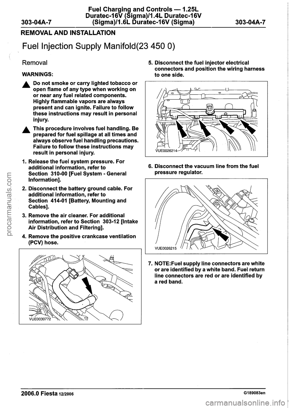
5. Disconnect the fuel injector electrical
connectors and position the wiring harness
to one side.
1. Release the fuei system pressure. For
additional information, refer to 6. Disconnect the vacuum line from the fuel
Section
31 0-00 [Fuel System - General pressure
regulator.
Information].
2. Disconnect the battery ground cable. For
additional information, refer to
Section
414-01 [Battery, Mounting and
Cables].
3. Remove the air cleaner. For additional
information, refer to Section
303-12 [Intake
Air Distribution and Filtering].
4. Remove the positive crankcase ventilation
(PCV) hose.
7. N0TE:Fuel supply line connectors are white
or are identified by a white band. Fuel return
line connectors are red or are identified by
a red band.
2006.0 Fiesta 1212006 GI 89083en
procarmanuals.com
Page 806 of 1226

Fuel Charging and Controls - 1.25L
Duratec-I 6V (Sigma)ll.4L Duratec-I 6V
(Sigma)ll.6L Duratec-1 6V (Sigma)
REMOVAL AND INSTALLATION
Disconnect the fuel supply line from the fuel 10. Remove the fuel pressure regulator.
injection supply manifold. For additional
information, refer to Section 31 0-00 [Fuel
System
- General Information].
8. N0TE:Fuel supply line connectors are white
or are identified by a white band. Fuel return
line connectors are red or are identified by
a red band.
Disconnect the fuel return line from the fuel
injection supply manifold. For additional
information, refer to Section 31 0-00 [Fuel
System
- General Information].
9. Remove the fuel injection supply manifold.
11. Remove and discard the O-ring seal.
12.
N0TE:Discard the fuel injector O-ring seals.
Remove the fuel injectors from the fuel
injection supply manifold.
1. Lift the retaining clip.
2. Slide the retaining clip. .
3. Pull the fuel injector.
2006.0 Fiesta 1212006 GI 89083en
procarmanuals.com
Page 807 of 1226
Fuel Charging and Controls - 1.25L
Duratec-I 6V (Sigma)llI4L Duratec-1 6V
303-04A-9 (Sigma)ll .6L Duratec-1 6V (Sigma) 303-04A-9
REMOVAL AND INSTALLATION
13. Remove and discard the O-ring seals.
Installation
WARNINGS:
A Do not smoke or carry lighted tobacco or
open flame of any type when working on
or near any fuel related components.
Highly flammable vapors are always
present and can ignite. Failure to follow
these instructions may result in personal
injury.
( A This procedure involves fuel handling. Be ' prepared for fuel spillage at all times and
always observe fuel handling precautions.
Failure to follow these instructions may
result in personal injury.
1. N0TE:lnstall new fuel injector O-ring seals.
N0TE:lnstall a new fuel pressure regulator O-ring
seal.
.
N0TE:Lubricate the O-ring seals with clean engine
oil to aid installation.
To install, reverse the removal procedure.
2006.0 Fiesta IZIZOO~ GI 89083en
procarmanuals.com
Page 900 of 1226

Engine Emission Control - 2.OL Duratec-HE
303-08B-6
(MI41 303-08B-6
DIAGNOSIS AND TESTING
Engine Emission Control
lnspection and Verification
General Equipment Visual Inspection Chart L..
I. Verify the customer concern.
2. Visually inspect for obvious signs of mechanical
or electrical damage.
Worldwide Diagnostic System
(WDS)
- Hose(s)/hose joints
- Gasket(s)
- Positive crankcase
ventilation (PCV)
valve
- PCV separator
Mechanical
- Exhaust gas recircu-
lation (EGR) valve
Electrical
- Electrical
con
nector(s)
- Wiring harness
- Fuse(s)
- Relay
- EGRvalve
- Powertain control
module (PCM)
3. If an obvious cause for an observed or reported
concern is found, correct the cause (if possible)
before proceeding to the next step.
4. If the concern is not visually evident, verify the
symptom and refer to the Symptom Chart.
Symptom Chart
Symptom Chart
Symptom Possible Sources Action
I
Poor engine performance EGR valve.
Using WDS, CHECK the EGR
Valve Duty Cycle input signal
I to the EGR vacuum regulator
valve. If the result is 0%,
REMOVE the EGR valve.
REFER to Exhaust Gas Recir-
culation (EGR) Valve
- in this
section.
INSPECT the EGR valve and
valve seat for damage. Make
sure that the EGR valve is in
the closed position. If the EGR
valve is not closed. INSTALL
a
new EGR valve. TEST the
system for normal operation. If
the result is not 0% continue
the engine diagnostic using
WDS.
2006.0 Fiesta 1212006 G334290en
Excessive crankcase pressure Blocked or damaged PCV
hose(s).
Blocked crankcase vent oil
separator. CHECK
the PCV system
components for blockages, CLEAN or INSTALL new
components as necessary.
procarmanuals.com
Page 1007 of 1226

Automatic Transmission/Transaxle -
Vehicles With: 4-Speed Automatic
307-01 47 Transmission (AW81-40) 307-01 -47
DIAGNOSIS AND TESTING
Symptom Possible Sources Action
'
U2516 CAN bus off transmit
error
I 5750 Throttle open malfunction 1 . CAN bus. 1. REFER to WDS. I
CAN bus.
U1900 CAN Communication
bus fault error
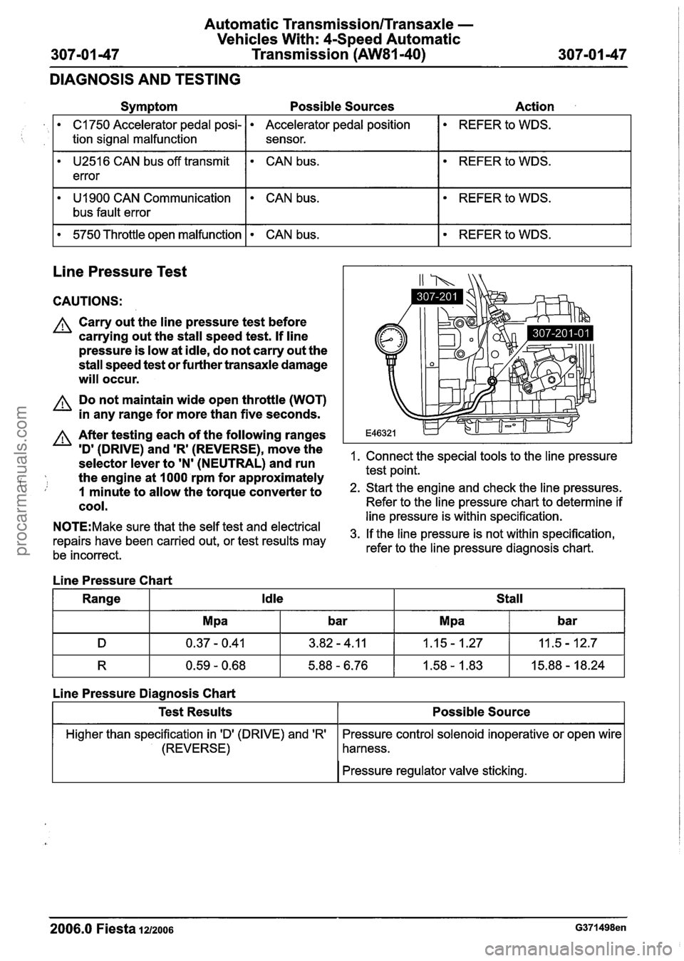
Line Pressure Test
C1750 Accelerator pedal posi-
tion signal malfunction
. CAN bus.
CAUTIONS:
A Carry out the line pressure test before
carrying out the stall speed test.
If line
pressure is low at idle, do not carry out the
stall speed test or further transaxle damage
will occur.
Accelerator pedal position
sensor.
A Do not maintain wide open throttle (WOT)
in any range for more than five seconds.
REFER to WDS.
A After testing each of the following ranges
ID' (DRIVE) and 'R' (REVERSE)r move the 1. Connect the special tools to the line pressure selector lever to 'N' (NEUTRAL) and run
the engine at
I000 rpm for approximately test point.
i, 1 minute to allow the torque converter to 2. Start the engine and check the line pressures.
cool. Refer to the line pressure chart to determine if -- --- line pressure is within specification. N0TE:Make sure that the self test and electrical 3m If the line pressure is not within specification, repairs have been carried out, or test results may
be incorrect. refer to the
line pressure diagnosis chart.
Line Pressure Chart
Range
Idle Stall
R 0.59 - 0.68 5.88 - 6.76 1.58 - 1.83 15.88 - 18.24
Line Pressure Diagnosis Chart
I I Pressure regulator valve sticking. I
Test Results
Higher than specification in 'D' (DRIVE) and 'R'
(REVERSE)
2006.0 Fiesta 1212006 G371498en
Possible Source
Pressure control solenoid inoperative or open wire
harness.
procarmanuals.com