Page 217 of 384

Brake Force Distribution (EBD) systems are not function-
ing. Immediate repair to the ABS system is required.
POWER STEERING
The standard power steering system will give you good
vehicle response and increased ease of maneuverability
in tight spaces. The system will provide mechanical
steering capability if power assist is lost.
If for some reason the power assist is interrupted, it will
still be possible to steer your vehicle. Under these condi-
tions, you will observe a substantial increase in steering
effort, especially at very low vehicle speeds and during
parking maneuvers.
NOTE:Increased noise levels at the end of the steering
wheel travel are considered normal and do not indicate
that there is a problem with the power steering system.
Upon initial start-up in cold weather, the power
steering pump may make noise for a short amount of
time. This is due to the cold, thick fluid in the steering
system. This noise should be considered normal, and
does not in any way damage the steering system.
WARNING!
Continued operation with reduced power steering
assist could pose a safety risk to yourself and others.
Service should be obtained as soon as possible.
CAUTION!
Prolonged operation of the steering system at the
end of the steering wheel travel will increase the
steering fluid temperature and it should be avoided
when possible. Damage to the power steering pump
may occur.
STARTING AND OPERATING 217
5
Page 218 of 384

MULTI DISPLACEMENT SYSTEM (MDS) - 5.7L
Engine Only
This feature offers improved fuel economy by shutting
off four of the engine’s eight cylinders during light load
and cruise conditions. The system is automatic with no
driver inputs or additional driving skills required.
NOTE:The MDS system may take some time to return
to full functionality after a battery disconnect.
TRACTION CONTROL SYSTEM (TCS) — IF
EQUIPPED
WARNING!
The Traction Control System (TCS) cannot prevent
the natural laws of physics from acting on the
vehicle, nor can it increase the traction afforded. The
TCS cannot prevent accidents, including those re-
sulting from excessive speed in turns, or hydroplan-
ing. Only a safe, attentive, and skillful driver can
prevent accidents. The capabilities of a TCS-
equipped vehicle must never be exploited in a reck-
less or dangerous manner, which could jeopardize
the user’s safety or the safety of others.
The Traction Control System (TCS) Indicator
Light, located in the instrument cluster, starts
to flash as soon as the tires lose traction and the
wheels begin to spin. This indicates that the
TCS is active. If the indicator light begins to flash during
218 STARTING AND OPERATING
Page 219 of 384

acceleration, ease up on the accelerator and apply as little
throttle as possible. Be sure to adapt your speed and
driving to the prevailing road conditions.
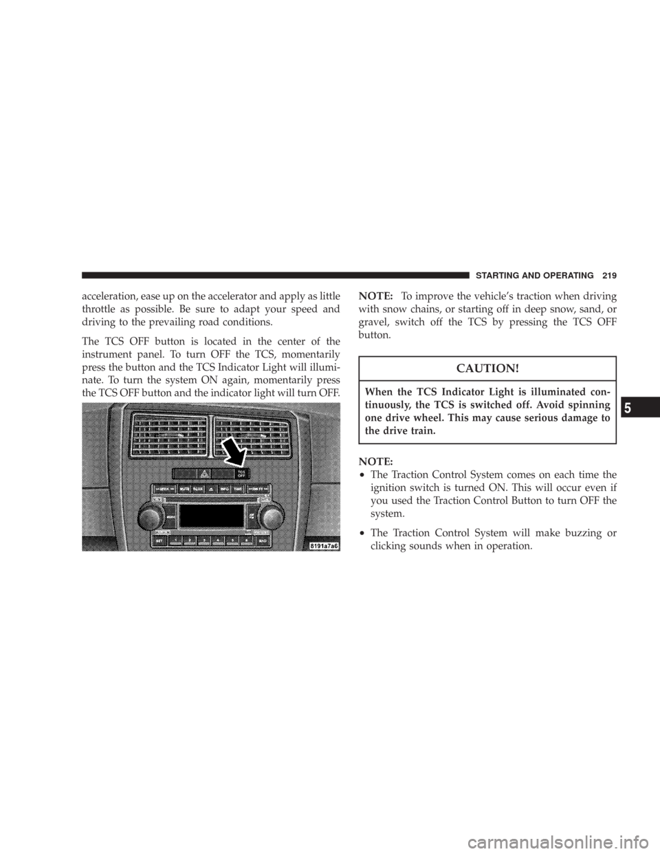
The TCS OFF button is located in the center of the
instrument panel. To turn OFF the TCS, momentarily
press the button and the TCS Indicator Light will illumi-
nate. To turn the system ON again, momentarily press
the TCS OFF button and the indicator light will turn OFF.NOTE:To improve the vehicle’s traction when driving
with snow chains, or starting off in deep snow, sand, or
gravel, switch off the TCS by pressing the TCS OFF
button.
CAUTION!
When the TCS Indicator Light is illuminated con-
tinuously, the TCS is switched off. Avoid spinning
one drive wheel. This may cause serious damage to
the drive train.
NOTE:
•
The Traction Control System comes on each time the
ignition switch is turned ON. This will occur even if
you used the Traction Control Button to turn OFF the
system.
•The Traction Control System will make buzzing or
clicking sounds when in operation.
STARTING AND OPERATING 219
5
Page 220 of 384

BRAKE ASSIST SYSTEM (BAS) — IF EQUIPPED
WARNING!
The BAS (Brake Assist System) cannot prevent the
natural laws of physics from acting on the vehicle,
nor can it increase the traction afforded by prevail-
ing road conditions. The BAS cannot prevent acci-
dents, including those resulting from excessive
speed in turns, driving on very slippery surfaces, or
hydroplaning. Only a safe, attentive, and skillful
driver can prevent accidents. The capabilities of a
BAS-equipped vehicle must never be exploited in a
reckless or dangerous manner, which could jeopar-
dize the user’s safety or the safety of others.
The Brake Assist System (BAS) is standard on vehicles
equipped with Electronic Stability Program (ESP). The
BAS is designed to optimize the vehicle’s braking capa-
bility during emergency braking maneuvers. The system
applies optimum pressure to the brakes in emergency
braking conditions than might otherwise be afforded
solely by the driver’s braking style. This can help reduce
braking distances. The BAS complements the Anti-Lock
Brake System (ABS). Applying the brakes very quickly
results in the best BAS assistance. To receive the benefit of
the system, you must apply continuous braking power
during the stopping sequence. Do not reduce brake pedal
pressure. Once the brake pedal is released, the BAS is
deactivated.
220 STARTING AND OPERATING
Page 221 of 384

ELECTRONIC STABILITY PROGRAM (ESP) — IF
EQUIPPED
WARNING!
The ESP (Electronic Stability Program) cannot pre-
vent the natural laws of physics from acting on the
vehicle, nor can it increase the traction afforded by
prevailing road conditions. The ESP cannot prevent
accidents, including those resulting from excessive
speed in turns, driving on very slippery surfaces, or
hydroplaning. Only a safe, attentive, and skillful
driver can prevent accidents. The capabilities of an
ESP-equipped vehicle must never be exploited in a
reckless or dangerous manner, which could jeopar-
dize the user’s safety or the safety of others.
This system enhances directional control and stability of
the vehicle under various driving conditions. The ESP
corrects for oversteering and understeering the vehicle
by applying the brake of the appropriate wheel. Enginepower may also be reduced to assist in counteracting the
condition of oversteer or understeer and help the vehicle
maintain the desired path.
The ESP uses sensors in the vehicle to determine the path
that the driver intends to steer the vehicle and compares
it to the actual path of the vehicle. When the actual path
does not match the intended path, the ESP applies the
brake of the appropriate wheel to assist in counteracting
the condition of oversteer or understeer.
•Oversteer - when the vehicle is turning more than
appropriate for the steering wheel position.
•Understeer - when the vehicle is turning less than
appropriate for the steering wheel position.
The ESP/TCS Indicator Light, located in the
instrument cluster, starts to flash as soon as the
tires lose traction and the ESP system becomes
active. The indicator light also flashes when the
TCS is active. If the indicator light begins to flash during
acceleration, ease up on the accelerator and apply as little
throttle as possible. Be sure to adapt your speed and
driving to the prevailing road conditions.
STARTING AND OPERATING 221
5
Page 222 of 384

The ESP OFF button is located in the center of the
instrument panel. To turn OFF the ESP, momentarily
press the ESP OFF button and the ESP/TCS Indicator
Light will illuminate. To turn the system ON again,
momentarily press the ESP OFF button and the indicator
light will turn OFF.
NOTE:To improve the vehicle’s traction when driving
with snow chains, or starting off in deep snow, sand, or
gravel, switch off the ESP by pressing the ESP OFF
button.When ESP is switched off, the engine torque reduction
feature is cancelled. Therefore, the enhanced vehicle
stability offered by ESP is unavailable. However, a fea-
ture of the system remains active. This feature controls
wheel spin across an axle quite similarly to a limited slip
differential. If one wheel on an axle is spinning faster
than the other, the system will apply the brake of the
spinning wheel and allow more engine torque to be
applied to the wheel that is not spinning. This wheel slip
control is active at vehicle speeds between approximately
24 mph (40 km/h) and 50 mph (80 km/h).
CAUTION!
When the ESP/TCS Indicator Light is illuminated
continuously, the ESP is switched off. Avoid spin-
ning one drive wheel. This may cause serious dam-
age to the drive train.
222 STARTING AND OPERATING
Page 223 of 384

CAUTION!
If the vehicle is towed with the front axle raised, the
engine must be shut off (key in the ignition switch to
the OFF/LOCK or ACC position). Otherwise, the ESP
will immediately be engaged and will apply the rear
wheel brakes.
Synchronizing ESP
The malfunction indicator light for the ESP is
combined with BAS indicator. If the power
supply is interrupted (battery disconnected or
discharged), the ESP/BAS malfunction indica-
tor light may illuminate with the engine running. If this
should occur, turn the steering wheel completely to the
left and then to the right. The ESP/BAS malfunction
indicator light should go out.
ESP/BAS Malfunction Indicator and ESP/TCS
Indicator Lights
The malfunction indicator light for the ESP is
combined with the BAS indicator. The yellow
ESP/BAS malfunction indicator light and the
yellow ESP/TCS indicator light in the instru-
ment cluster both come on when the ignition switch is
turned to the “ON” position. They should go out with the
engine running.
The system will turn the ESP/BAS malfunction indicator
light on continuously while the engine running if it
detects a malfunction in either the ESP or the BAS or
both. If the light remains on after several ignition cycles,
and you have driven the vehicle several miles at speeds
greater than 30 mph (48 km/h), and the ESP is synchro-
nized (refer to Synchronizing ESP), see your authorized
dealer as soon as possible to have the problem diagnosed
and corrected.
STARTING AND OPERATING 223
5
Page 224 of 384

TIRE SAFETY INFORMATION
Tire Markings
NOTE:
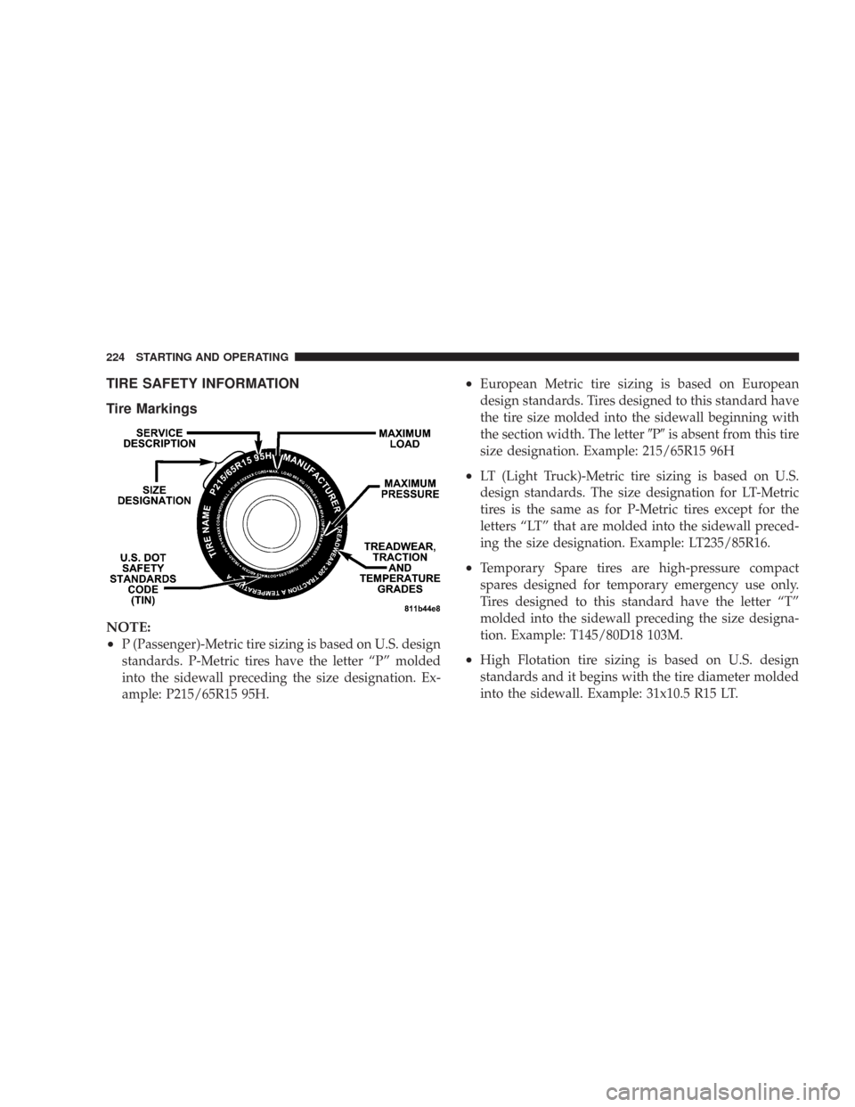
•
P (Passenger)-Metric tire sizing is based on U.S. design
standards. P-Metric tires have the letter “P” molded
into the sidewall preceding the size designation. Ex-
ample: P215/65R15 95H.
•European Metric tire sizing is based on European
design standards. Tires designed to this standard have
the tire size molded into the sidewall beginning with
the section width. The letterPis absent from this tire
size designation. Example: 215/65R15 96H
•LT (Light Truck)-Metric tire sizing is based on U.S.
design standards. The size designation for LT-Metric
tires is the same as for P-Metric tires except for the
letters “LT” that are molded into the sidewall preced-
ing the size designation. Example: LT235/85R16.
•Temporary Spare tires are high-pressure compact
spares designed for temporary emergency use only.
Tires designed to this standard have the letter “T”
molded into the sidewall preceding the size designa-
tion. Example: T145/80D18 103M.
•High Flotation tire sizing is based on U.S. design
standards and it begins with the tire diameter molded
into the sidewall. Example: 31x10.5 R15 LT.
224 STARTING AND OPERATING