Page 168 of 2000
INTRODUCTION – REPAIR INSTRUCTIONIN–23
IN
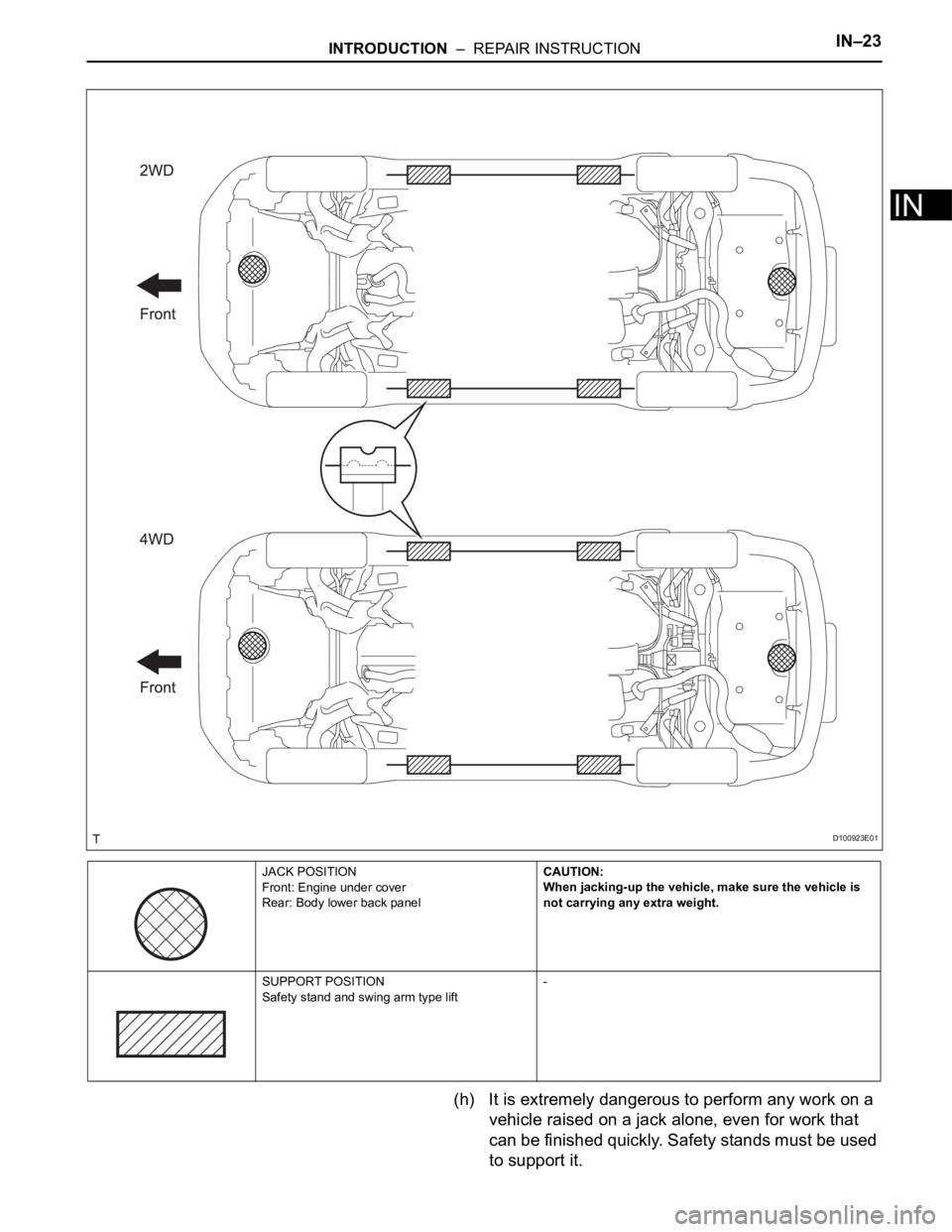
(h) It is extremely dangerous to perform any work on a
vehicle raised on a jack alone, even for work that
can be finished quickly. Safety stands must be used
to support it.
JACK POSITION
Front: Engine under cover
Rear: Body lower back panelCAUTION:
When jacking-up the vehicle, make sure the vehicle is
not carrying any extra weight.
SUPPORT POSITION
Safety stand and swing arm type lift-
D100923E01
Page 583 of 2000
EM–262AZ-FE ENGINE MECHANICAL – TIMING CHAIN
EM
(b) Remove the crankshaft pulley.
HINT:
If necessary, remove the pulley and pulley bolt using
SST.
SST 09950-50013 (09951-05010, 09952-05010,
09953-05020, 09954-05021), 09950-40011
(09957-04010)
22. REMOVE NO. 1 CHAIN TENSIONER ASSEMBLY
(a) Remove the 2 nuts, chain tensioner and gasket.
NOTICE:
Do not turn the crankshaft without the chain
tensioner.
23. REMOVE ENGINE MOUNTING BRACKET RH
(a) Remove the 3 bolts and engine mounting bracket
RH.
24. REMOVE V-RIBBED BELT TENSIONER ASSEMBLY
(a) Lift the engine upward using the transmission jack.
NOTICE:
Do not lift the engine more than necessary.
(b) Remove the bolt, nut and V-ribbed belt tensioner.
25. REMOVE CRANKSHAFT POSITION SENSOR (See
page ES-402)
26. REMOVE TIMING CHAIN COVER SUB-ASSEMBLY
(a) Using an E10 "torx" socket, remove the stud bolt for
the V-ribbed belt tensioner.
A124860E01
A098348E01
A128165
A112212
A014253E03
Page 597 of 2000

EM–402AZ-FE ENGINE MECHANICAL – TIMING CHAIN
EM
(d) Uniformly tighten the 12 bolts and 2 nuts in the
sequence shown in the illustration.
Torque: 9.0 N*m (92 kgf*cm, 80 in.*lbf)
(e) Place a transmission jack underneath the engine,
then put a wooden block on the jack.
(f) Remove the chain block and sling device.
(g) Remove the No. 1 and No. 2 engine hangers.
14. INSTALL CRANKSHAFT POSITION SENSOR (See
page ES-402)
15. INSTALL CYLINDER HEAD COVER SUB-ASSEMBLY
(a) Remove any old packing material from the contact
surface.
(b) Apply seal packing to the 2 locations shown in the
illustration.
Seal packing:
Toyota Genuine Seal Packing Block, Three
Bond 1207B or Equivalent
NOTICE:
• Remove any oil from the contact surface.
• Install the oil pan within 3 minutes of applying
seal packing.
• Do not add engine oil for at least 2 hours after
installing the oil pan.
(c) Install the cylinder head cover with the 8 bolts and 2
nuts.
Torque: 11 N*m (112 kgf*cm, 8 ft.*lbf) for bolt A
14 N*m (143 kgf*cm, 10 ft.*lbf) for bolt B
11 N*m (112 kgf*cm, 8 ft.*lbf) for nut
A114333E01
A061184E04
A094205E01
A094204E01
Page 1423 of 2000
DIFFERENTIAL – REAR DIFFERENTIAL CARRIER ASSEMBLYDF–19
DF
(d) Support the rear differential carrier with a
transmission jack or equivalent.
(e) Fix the nuts in place and remove bolt A, bolt B and
bolt C.
NOTICE:
Do not loosen the nuts. Loosen the bolts.
(f) Slowly lower the jack and then tilt the rear
differential carrier.
(g) Set the tip of the tire lever to the position on the rear
drive shaft inboard joint shown in the illustration.
Then, using the ribbed part of the rear differential
carrier as a fulcrum, disconnect the left and right
rear drive shafts.
NOTICE:
Do not scratch the rear drive shaft dust cover.
C129479E01
C129480
C129481