2006 TOYOTA RAV4 wiring
[x] Cancel search: wiringPage 1149 of 2000
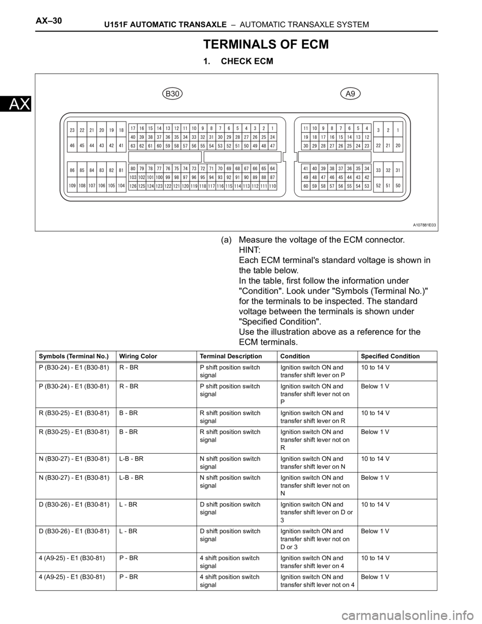
AX–30U151F AUTOMATIC TRANSAXLE – AUTOMATIC TRANSAXLE SYSTEM
AX
TERMINALS OF ECM
1. CHECK ECM
(a) Measure the voltage of the ECM connector.
HINT:
Each ECM terminal's standard voltage is shown in
the table below.
In the table, first follow the information under
"Condition". Look under "Symbols (Terminal No.)"
for the terminals to be inspected. The standard
voltage between the terminals is shown under
"Specified Condition".
Use the illustration above as a reference for the
ECM terminals.
A107881E03
Symbols (Terminal No.) Wiring Color Terminal Description ConditionSpecified Condition
P (B30-24) - E1 (B30-81) R - BR P shift position switch
signalIgnition switch ON and
transfer shift lever on P10 to 14 V
P (B30-24) - E1 (B30-81) R - BR P shift position switch
signalIgnition switch ON and
transfer shift lever not on
PBelow 1 V
R (B30-25) - E1 (B30-81) B - BR R shift position switch
signalIgnition switch ON and
transfer shift lever on R10 to 14 V
R (B30-25) - E1 (B30-81) B - BR R shift position switch
signalIgnition switch ON and
transfer shift lever not on
RBelow 1 V
N (B30-27) - E1 (B30-81) L-B - BR N shift position switch
signalIgnition switch ON and
transfer shift lever on N10 to 14 V
N (B30-27) - E1 (B30-81) L-B - BR N shift position switch
signalIgnition switch ON and
transfer shift lever not on
NBelow 1 V
D (B30-26) - E1 (B30-81) L - BR D shift position switch
signalIgnition switch ON and
transfer shift lever on D or
310 to 14 V
D (B30-26) - E1 (B30-81) L - BR D shift position switch
signalIgnition switch ON and
transfer shift lever not on
D or 3Below 1 V
4 (A9-25) - E1 (B30-81) P - BR 4 shift position switch
signalIgnition switch ON and
transfer shift lever on 410 to 14 V
4 (A9-25) - E1 (B30-81) P - BR 4 shift position switch
signalIgnition switch ON and
transfer shift lever not on 4Below 1 V
Page 1150 of 2000

U151F AUTOMATIC TRANSAXLE – AUTOMATIC TRANSAXLE SYSTEMAX–31
AX
3 (B30-29) - E1 (B30-81) LG - BR 3 shift position switch
signalIgnition switch ON and
transfer shift lever on 310 to 14 V
3 (B30-29) - E1 (B30-81) LG - BR 3 shift position switch
signalIgnition switch ON and
transfer shift lever not on 3Below 1 V
2 (B30-28) - E1 (B30-81) V - BR 2 shift position switch
signalIgnition switch ON and
transfer shift lever on 2
and L10 to 14 V
2 (B30-28) - E1 (B30-81) V - BR 2 shift position switch
signalIgnition switch ON and
transfer shift lever not on 2
and LBelow 1 V
L (A9-26) - E1 (B30-81) V - BR L shift position switch
signalIgnition switch ON and
transfer shift lever on L10 to 14 V
L (A9-26) - E1 (B30-81) V - BR L shift position switch
signalIgnition switch ON and
transfer shift lever not on LBelow 1 V
STP (A9-36) - E1 (B30-81) L - BR Stop light switch signal Brake pedal is depressed Between 10 V and 14 V
STP (A9-36) - E1 (B30-81) L - BR Stop light switch signal Brake pedal is released Below 1 V
SL1+ (B30-16) - SL1-
(B30-17)P - LG SL1 solenoid signal Engine idle speed Pulse generation
(see waveform 1)
SL1+ (B30-16) - SL1-
(B30-17)P - LG SL1 solenoid signal Ignition switch ON Pulse generation
(see waveform 1)
SL1+ (B30-16) - SL1-
(B30-17)P - LG SL1 solenoid signal 1st gear Pulse generation
(see waveform 1)
SL1+ (B30-16) - SL1-
(B30-17)P - LG SL1 solenoid signal Not on 1st gear Below 1 V
SL2+ (B30-12) - SL2-
(B30-13)BR - R SL2 solenoid signal Engine idle speed Pulse generation
(see waveform 2)
SL2+ (B30-12) - SL2-
(B30-13)BR - R SL2 solenoid signal Ignition switch ON Pulse generation
(see waveform 2)
SL2+ (B30-12) - SL2-
(B30-13)BR - R SL2 solenoid signal 1st or 2nd gear Pulse generation
(see waveform 2)
SL2+ (B30-12) - SL2-
(B30-13)BR - R SL2 solenoid signal 3rd, 4th or 5th gear Below 1 V
SL3+ (B30-14) - SL3-
(B30-15)GR - G-R SL3 solenoid signal Engine idle speed Pulse generation
(see waveform 3)
SL3+ (B30-14) - SL3-
(B30-15)GR - G-R SL3 solenoid signal Ignition switch ON Pulse generation
(see waveform 3)
SL3+ (B30-14) - SL3-
(B30-15)GR - G-R SL3 solenoid signal 1st or 2nd gear Pulse generation
(see waveform 3)
SL3+ (B30-14) - SL3-
(B30-15)GR - G-R SL3 solenoid signal 3rd, 4th or 5th gear Below 1 V
DSL (B30-9) - E01 (B30-
22)V - BR DSL solenoid signal Vehicle speed 65 km/h (40
mph), lock-up (ON to OFF)Below 1 V
DSL (B30-9) - E01 (B30-
22)V - BR DSL solenoid signal Vehicle driving under lock-
up positionPulse generation
(see waveform 4)
SLT+ (B30-11) - SLT-
(B30-10)L - W SLT solenoid signal Engine idle speed Pulse generation
(see waveform 5)
SR (B30-8) - E01 (B30-22) G - BR SR solenoid signal Ignition switch ON Below 1 V
SR (B30-8) - E01 (B30-22) G - BR SR solenoid signal 3th, 4th or 5th gear 10 to 14 V
SR (B30-8) - E01 (B30-22) G - BR SR solenoid signal 1st or 2nd gear Below 1 V
S4 (B30-7) - E01 (B30-22) L-B - BR S4 solenoid signal Ignition switch ON Below 1 V
S4 (B30-7) - E01 (B30-22) L-B - BR S4 solenoid signal 5th gear 10 to 14 V
S4 (B30-7) - E01 (B30-22) L-B - BR S4 solenoid signal Not on 5th gear Below 1 V
THO1 (B30-126) - ETHO
(B30-124)Y - B ATF temperature sensor
signalATF temperature 115
C
(239
F) or moreBelow 1.5 V
NT+ (B30-6) - NT- (B30-5) B - G Speed sensor (NT) signal Vehicle speed 20 km/h (12
mph)Pulse generation
(see waveform 6) Symbols (Terminal No.) Wiring Color Terminal Description ConditionSpecified Condition
Page 1151 of 2000
AX–32U151F AUTOMATIC TRANSAXLE – AUTOMATIC TRANSAXLE SYSTEM
AX
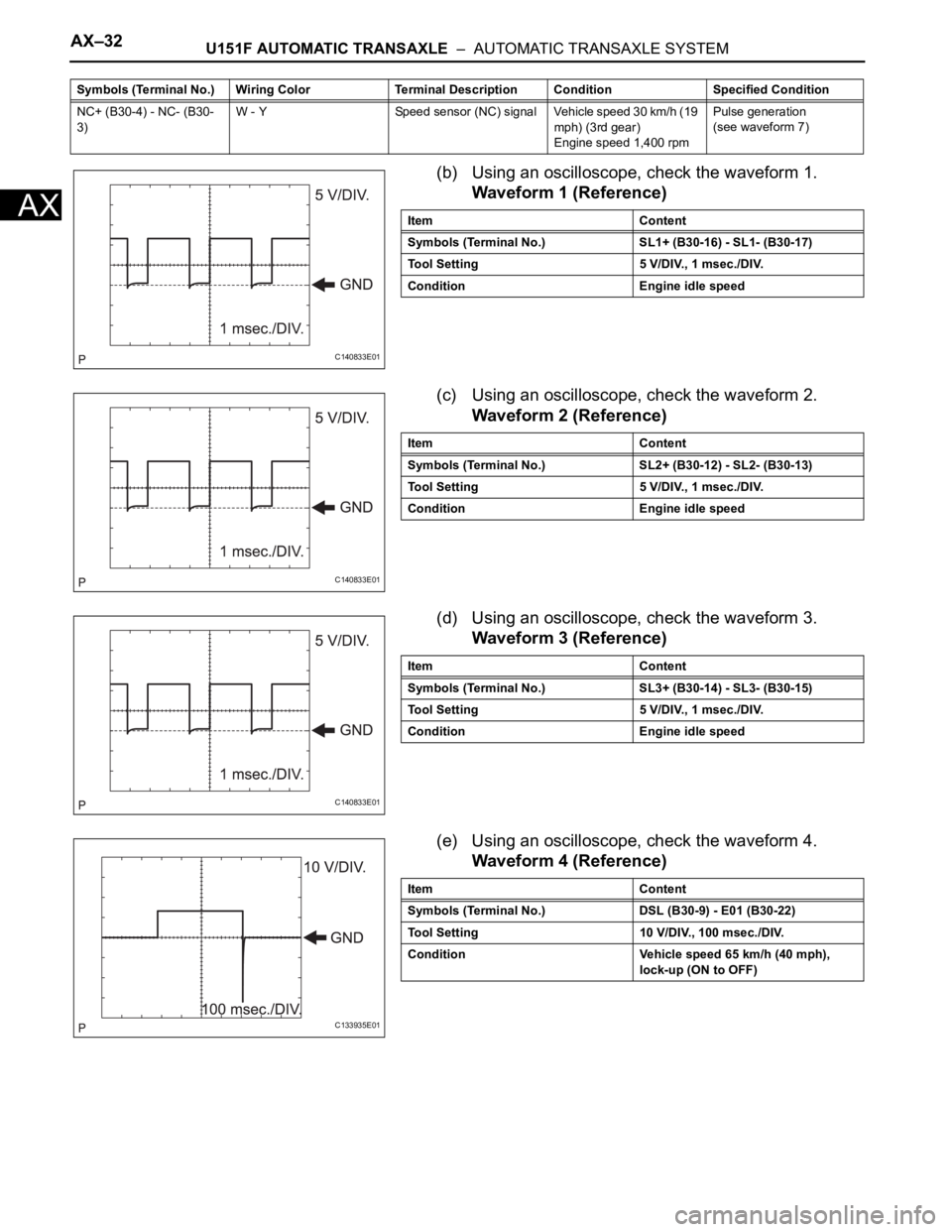
(b) Using an oscilloscope, check the waveform 1.
Waveform 1 (Reference)
(c) Using an oscilloscope, check the waveform 2.
Waveform 2 (Reference)
(d) Using an oscilloscope, check the waveform 3.
Waveform 3 (Reference)
(e) Using an oscilloscope, check the waveform 4.
Waveform 4 (Reference)
NC+ (B30-4) - NC- (B30-
3)W - Y Speed sensor (NC) signal Vehicle speed 30 km/h (19
mph) (3rd gear)
Engine speed 1,400 rpmPulse generation
(see waveform 7) Symbols (Terminal No.) Wiring Color Terminal Description ConditionSpecified Condition
C140833E01
Item Content
Symbols (Terminal No.) SL1+ (B30-16) - SL1- (B30-17)
Tool Setting 5 V/DIV., 1 msec./DIV.
Condition Engine idle speed
C140833E01
Item Content
Symbols (Terminal No.) SL2+ (B30-12) - SL2- (B30-13)
Tool Setting 5 V/DIV., 1 msec./DIV.
Condition Engine idle speed
C140833E01
Item Content
Symbols (Terminal No.) SL3+ (B30-14) - SL3- (B30-15)
Tool Setting 5 V/DIV., 1 msec./DIV.
Condition Engine idle speed
C133935E01
Item Content
Symbols (Terminal No.) DSL (B30-9) - E01 (B30-22)
Tool Setting 10 V/DIV., 100 msec./DIV.
Condition Vehicle speed 65 km/h (40 mph),
lock-up (ON to OFF)
Page 1253 of 2000
U241E AUTOMATIC TRANSAXLE – AUTOMATIC TRANSAXLE SYSTEMAX–29
AX
TERMINALS OF ECM
1. CHECK ECM
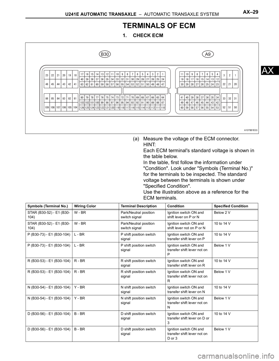
(a) Measure the voltage of the ECM connector.
HINT:
Each ECM terminal's standard voltage is shown in
the table below.
In the table, first follow the information under
"Condition". Look under "Symbols (Terminal No.)"
for the terminals to be inspected. The standard
voltage between the terminals is shown under
"Specified Condition".
Use the illustration above as a reference for the
ECM terminals.
A107881E03
Symbols (Terminal No.) Wiring Color Terminal Description ConditionSpecified Condition
STAR (B30-52) - E1 (B30-
104)W - BR Park/Neutral position
switch signalIgnition switch ON and
shift lever on P or NBelow 2 V
STAR (B30-52) - E1 (B30-
104)W - BR Park/Neutral position
switch signalIgnition switch ON and
shift lever not on P or N10 to 14 V
P (B30-73) - E1 (B30-104) L - BR P shift position switch
signalIgnition switch ON and
transfer shift lever on P10 to 14 V
P (B30-73) - E1 (B30-104) L - BR P shift position switch
signalIgnition switch ON and
transfer shift lever not on
PBelow 1 V
R (B30-53) - E1 (B30-104) R - BR R shift position switch
signalIgnition switch ON and
transfer shift lever on R10 to 14 V
R (B30-53) - E1 (B30-104) R - BR R shift position switch
signalIgnition switch ON and
transfer shift lever not on
RBelow 1 V
N (B30-54) - E1 (B30-104) Y - BR N shift position switch
signalIgnition switch ON and
transfer shift lever on N10 to 14 V
N (B30-54) - E1 (B30-104) Y - BR N shift position switch
signalIgnition switch ON and
transfer shift lever not on
NBelow 1 V
D (B30-56) - E1 (B30-104) B - BR D shift position switch
signalIgnition switch ON and
transfer shift lever on D or
310 to 14 V
D (B30-56) - E1 (B30-104) B - BR D shift position switch
signalIgnition switch ON and
transfer shift lever not on
D or 3Below 1 V
Page 1254 of 2000

AX–30U241E AUTOMATIC TRANSAXLE – AUTOMATIC TRANSAXLE SYSTEM
AX
3 (A9-26) - E1 (B30-104) P - BR 3 shift position switch
signalIgnition switch ON and
transfer shift lever on 310 to 14 V
3 (A9-26) - E1 (B30-104) P - BR 3 shift position switch
signalIgnition switch ON and
transfer shift lever not on 3Below 1 V
2 (B30-55) - E1 (B30-104) P - BR 2 shift position switch
signalIgnition switch ON and
transfer shift lever on 2
and L10 to 14 V
2 (B30-55) - E1 (B30-104) P - BR 2 shift position switch
signalIgnition switch ON and
transfer shift lever not on 2
and LBelow 1 V
L (B30-74) - E1 (B30-104) LG - BR L shift position switch
signalIgnition switch ON and
transfer shift lever on L10 to 14 V
L (B30-74) - E1 (B30-104) LG - BR L shift position switch
signalIgnition switch ON and
transfer shift lever not on LBelow 1 V
STP (A9-36) - E1 (B30-
104)L - BR Stop light switch signal Brake pedal is depressed Between 10 V and 14 V
STP (A9-36) - E1 (B30-
104)L - BR Stop light switch signal Brake pedal is released Below 1 V
SL1+ (B30-57) - SL1-
(B30-77)V - P SL1 solenoid signal Engine idle speed Pulse generation
(see waveform 1)
SL1+ (B30-57) - SL1-
(B30-77)V - P SL1 solenoid signal Ignition switch ON Pulse generation
(see waveform 1)
SL1+ (B30-57) - SL1-
(B30-77)V - P SL1 solenoid signal 1st gear Pulse generation
(see waveform 1)
SL1+ (B30-57) - SL1-
(B30-77)V - P SL1 solenoid signal Not on 1st gear Below 1 V
SL2+ (B30-58) - SL2-
(B30-59)Y - L SL2 solenoid signal Engine idle speed Pulse generation
(see waveform 2)
SL2+ (B30-58) - SL2-
(B30-59)Y - L SL2 solenoid signal Ignition switch ON Pulse generation
(see waveform 2)
SL2+ (B30-58) - SL2-
(B30-59)Y - L SL2 solenoid signal 1st or 2nd gear Pulse generation
(see waveform 2)
SL2+ (B30-58) - SL2-
(B30-59)Y - L SL2 solenoid signal 3rd or O/D gear Below 1 V
DSL (B30-79) - E01 (B30-
45)G - BR DSL solenoid signal Vehicle speed 65 km/h (40
mph), lock-up (ON to OFF)Below 1 V
DSL (B30-79) - E01 (B30-
45)G - BR DSL solenoid signal Vehicle driving under lock-
up positionPulse generation
(see waveform 3)
SLT+ (B30-76) - SLT-
(B30-75)R - GR SLT solenoid signal Engine idle speed Pulse generation
(see waveform 4)
S4 (B30-78) - E01 (B30-
45)W - BR S4 solenoid signal Ignition switch ON Below 1 V
S4 (B30-78) - E01 (B30-
45)W - BR S4 solenoid signal O/D gear 10 to 14 V
S4 (B30-78) - E01 (B30-
45)W - BR S4 solenoid signal Not on O/D gear Below 1 V
THO1 (B30-72) - ETHO
(B30-95)LG- BR ATF temperature sensor
signalATF temperature: 115
C
(239F) or moreBelow 1.5 V
NT+ (B30-125) - NT- (B30-
124)W - R Speed sensor (NT) signal Vehicle speed 20 km/h (12
mph)Pulse generation
(see waveform 5)
NC+ (B30-101) - NC-
(B30-102)R - W Speed sensor (NC) signal Vehicle speed 30 km/h (19
mph): (3rd gear)
Engine speed 1,400 rpmPulse generation
(see waveform 6) Symbols (Terminal No.) Wiring Color Terminal Description ConditionSpecified Condition
Page 1344 of 2000
TF–16GF1A TRANSFER – ACTIVE TORQUE CONTROL 4WD SYSTEM
TF
TERMINALS OF ECU
1. CHECK 4WD CONTROL ECU
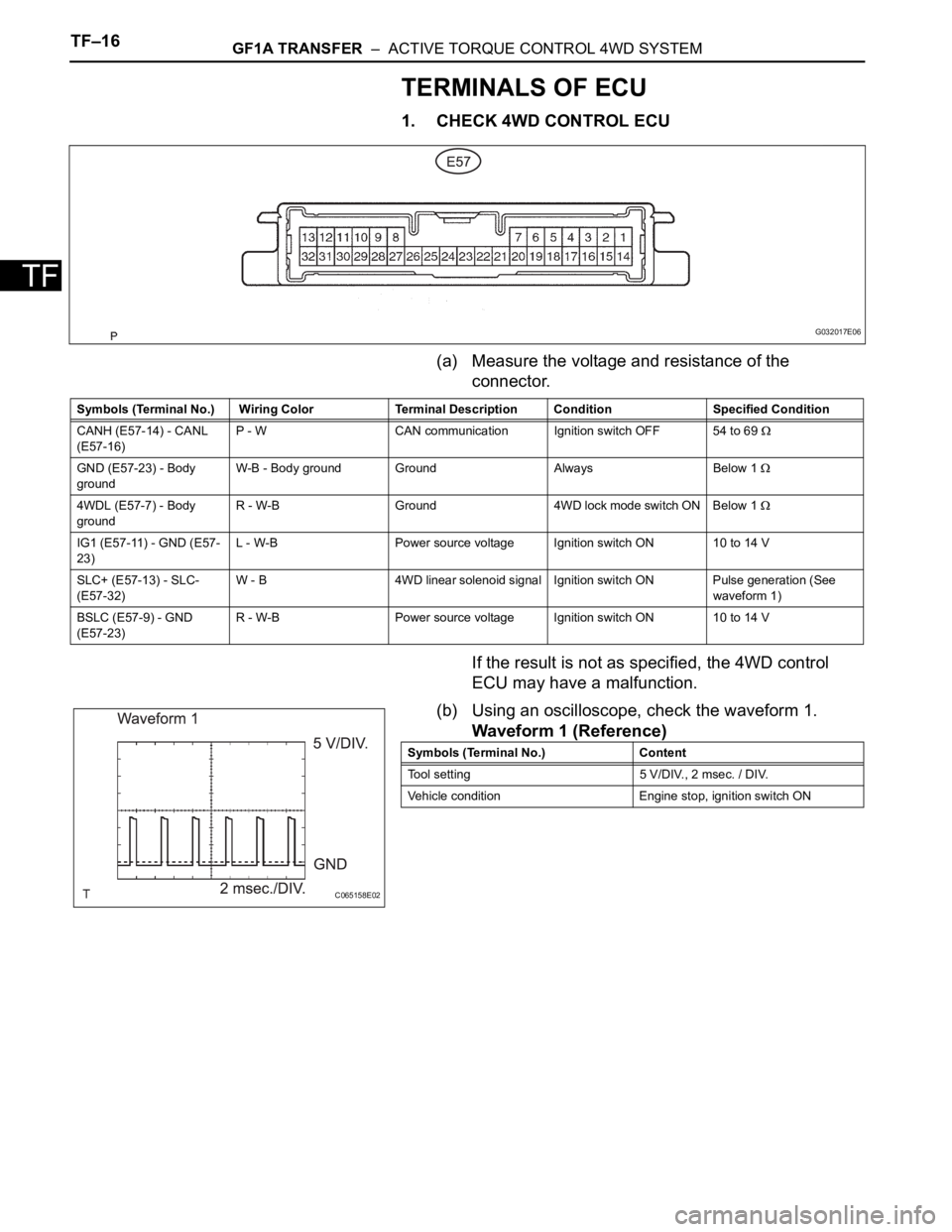
(a) Measure the voltage and resistance of the
connector.
If the result is not as specified, the 4WD control
ECU may have a malfunction.
(b) Using an oscilloscope, check the waveform 1.
Waveform 1 (Reference)
G032017E06
Symbols (Terminal No.) Wiring Color Terminal Description Condition Specified Condition
CANH (E57-14) - CANL
(E57-16)P - W CAN communication Ignition switch OFF 54 to 69
GND (E57-23) - Body
groundW-B - Body ground Ground Always Below 1
4WDL (E57-7) - Body
groundR - W-B Ground 4WD lock mode switch ON Below 1
IG1 (E57-11) - GND (E57-
23)L - W-B Power source voltage Ignition switch ON 10 to 14 V
SLC+ (E57-13) - SLC-
(E57-32)W - B 4WD linear solenoid signal Ignition switch ON Pulse generation (See
waveform 1)
BSLC (E57-9) - GND
(E57-23)R - W-B Power source voltage Ignition switch ON 10 to 14 V
C065158E02
Symbols (Terminal No.) Content
Tool setting 5 V/DIV., 2 msec. / DIV.
Vehicle condition Engine stop, ignition switch ON
Page 1352 of 2000
TF–24GF1A TRANSFER – ACTIVE TORQUE CONTROL 4WD SYSTEM
TF
DESCRIPTION
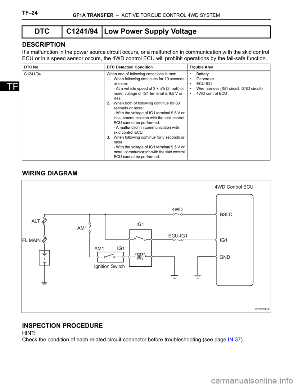
If a malfunction in the power source circuit occurs, or a malfunction in communication with the skid control
ECU or in a speed sensor occurs, the 4WD control ECU will prohibit operations by the fail-safe function.
WIRING DIAGRAM
INSPECTION PROCEDURE
HINT:
Check the condition of each related circuit connector before troubleshooting (see page IN-37).
DTC C1241/94 Low Power Supply Voltage
DTC No. DTC Detection Condition Trouble Area
C1241/94 When one of following conditions is met:
1. When following continues for 10 seconds
or more:
- At a vehicle speed of 3 km/h (2 mph) or
more, voltage of IG1 terminal is 9.5 V or
less.
2. When both of following continue for 60
seconds or more:
- With the voltage of IG1 terminal 9.5 V or
less, communication with the skid control
ECU cannot be performed.
- A malfunction in communication with
skid control ECU.
3. When following continue for 3 seconds or
more:
- With the voltage of IG1 terminal 9.5 V or
more, communication with the skid control
ECU cannot be performed.•Battery
• Generator
•ECU-IG1
• Wire harness (IG1 circuit, GND circuit)
• 4WD control ECU
C128626E02
Page 1358 of 2000
TF–30GF1A TRANSFER – ACTIVE TORQUE CONTROL 4WD SYSTEM
TF
DESCRIPTION
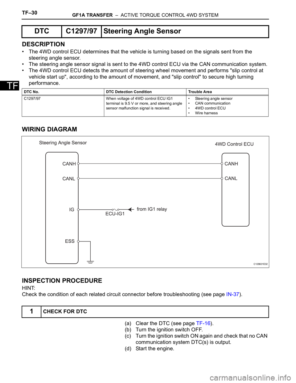
• The 4WD control ECU determines that the vehicle is turning based on the signals sent from the
steering angle sensor.
• The steering angle sensor signal is sent to the 4WD control ECU via the CAN communication system.
• The 4WD control ECU detects the amount of steering wheel movement and performs "slip control at
vehicle start up", according to the amount of movement, and "slip control" to secure high turning
performance.
WIRING DIAGRAM
INSPECTION PROCEDURE
HINT:
Check the condition of each related circuit connector before troubleshooting (see page IN-37).
(a) Clear the DTC (see page TF-16).
(b) Turn the ignition switch OFF.
(c) Turn the ignition switch ON again and check that no CAN
communication system DTC(s) is output.
(d) Start the engine.
DTC C1297/97 Steering Angle Sensor
DTC No. DTC Detection Condition Trouble Area
C1297/97 When voltage of 4WD control ECU IG1
terminal is 9.5 V or more, and steering angle
sensor malfunction signal is received.• Steering angle sensor
• CAN communication
• 4WD control ECU
• Wire harness
1CHECK FOR DTC
C128601E02