Page 560 of 2000

ES–362GR-FE ENGINE CONTROL SYSTEM – SFI SYSTEM
ES
VV2+ (B30-67) - VV2- (B30-90) W - B Variable valve timing
(VVT) sensor (Intake side
(bank 2))Idling Pulse generation
(see waveform 5)
EV1+ (B30-68) - EV1- (B30-91) Y - G Variable valve timing
(VVT) sensor (Exhaust
side (bank 1))Idling Pulse generation
(see waveform 5)
EV2+ (B30-66) - EV2- (B30-89) R - L Variable valve timing
(VVT) sensor (Exhaust
side (bank 2))Idling Pulse generation
(see waveform 5)
NE+ (B30-110) - NE- (B30-111) G - R Crankshaft position sensor Idling Pulse generation (see
waveform 5)
IGT1 (B30-40) - E1 (B30-81)
IGT2 (B30-39) - E1 (B30-81)
IGT3 (B30-38) - E1 (B30-81)
IGT4 (B30-37) - E1 (B30-81)
IGT5 (B30-36) - E1 (B30-81)
IGT6 (B30-35) - E1 (B30-81)W - BR
G-R - BR
G - BR
LG - BR
P - BR
V - BRIgnition coil (ignition
signal)Idling Pulse generation (see
waveform 6)
IGF1 (B30-106) - E1 (B30-81) Y - BR Ignition coil (ignition
confirmation signal)Ignition switch ON 4.5 to 5.5 V
Idling Pulse generation (see
waveform 6)
PRG (B30-108) - E1 (B30-81) LG - BR Purge VSV Ignition switch ON 9 to 14 V
Idling Pulse generation (see
waveform 7)
SPD (A9-8) - E1 (B30-81) V - BR Speed signal from
combination meterDriving at 20 km/h (12 mph) Pulse generation (see
waveform 8)
STA (A9-48) - E1 (B30-81) LG - BR Starter signal Cranking 5.5 V or more
NSW (B30-62) - E1 (B30-81) G-R - BR Starter relay control Ignition switch ON Below 1.5 V
Cranking 6.0 V or more
STP (A9-36) - E1 (B30-81) L - BR Stop light switch Brake pedal depressed 7.5 to 14 V
Brake pedal released Below 1.5 V
ST1- (A9-35) - E1 (B30-81) GR - BR Stop light switch
(opposite to STP terminal)Ignition switch ON,
Brake pedal depressedBelow 1.5 V
Ignition switch ON,
Brake pedal released7.5 to 14 V
M+ (B30-19) - ME01 (B30-20) G - BR Throttle actuator Idling with warm engine Pulse generation (see
waveform 9)
M- (B30-18) - ME01 (B30-20) R - BR Throttle actuator Idling with warm engine Pulse generation (see
waveform 10)
FC (A9-7) - E1 (B30-81) W - BR Fuel pump control Ignition switch ON 9 to 14 V
Idling Below 1.5 V
FPR (B30-59) - E1 (B30-81) W - BR Fuel pump control Cranking 9 to 14 V
FPR (B30-59) - E1 (B30-81) W - BR Fuel pump control Idling 9 to 14 V
W (A9-24) - E1 (B30-81) R - BR MIL Ignition switch ON Below 1.5 V
Idling 9 to 14 V
TC (A9-27) - E1 (B30-81) G - BR Terminal TC of DLC3 Ignition switch ON 9 to 14 V
TACH (A9-15) - E1 (B30-81) GR - BR Engine speed Idling Pulse generation (see
waveform 11)
VPMP (A9-42) - E1 (B30-81) W - BR Vent valve (built into
canister pump module)Ignition switch ON 9 to 14 V
MPMP (A9-34) - E1 (B30-81) B - BR Leak detection pump (built
into canister pump
module)Leak detection pump OFF Below 3 V
Leak detection pump ON 9 to 14 V
VCPP (B30-75) - EPPM (B30-76) V - BR Power source for canister
pressure sensor (specific
voltage)Ignition switch ON 4.5 to 5.5 V Symbol (Terminal No.) Wiring Color Terminal Description Condition Specified Condition
Page 561 of 2000

2GR-FE ENGINE CONTROL SYSTEM – SFI SYSTEMES–37
ES
HINT:
*: The ECM terminal voltage is constant regardless
of the output voltage from the sensor.
(b) WAVEFORM 1
Camshaft timing oil control valve (OCV)
PPMP (B30-77) - EPPM (B30-76) L - BR Canister pressure sensor
(built into canister pump
module)Ignition switch ON 3 to 3.6 V
ELS (A9-31) - E1 (B30-81) O - BR Electric load Taillight switch ON7.5 to 14 V
Taillight switch OFF Below 1.5 V
ELS2 (A9-33) - E1 (B30-81) G - BR Electric load Defogger switch ON7.5 to 14 V
Defogger switch OFF Below 1.5 V
ALT (B30-32) - E1 (B30-81) P - BR Generator Ignition switch ON 9 to 14 V
CANH (A9-41) - E1 (B30-81) Y - BR CAN communication line Ignition switch ON Pulse generation (see
waveform 12)
CANL (A9-49) - E1 (B30-81) W - BR CAN communication line Ignition switch ON Pulse generation (see
waveform 13)
VCIB (B30-80) - EIB (B30-101) LG - P Battery current sensor Ignition switch ON 4.5 to 5.5 V
IB (B30-100) - EIB (B30-101) R - P Battery current sensor Ignition switch ON 0.5 to 2.5 V
THB (B30-103) - EIB (B30-101) G-R - P Battery temperature
sensorIgnition switch ON, battery
temperature -30 to 80
C (-22 to
176
F)0.5 to 4.5 V
RLO (B30-31) - E1 (B30-81) Y - BR Generator After engine warmed up, during
charging control, vehicle driven at
constant speedPulse generation (see
waveform 14)
RLO (B30-31) - E1 (B30-81) Y - BR Generator After engine warmed up, during
charging control, vehicle
acceleratedPulse generation (see
waveform 15)
RLO (B30-31) - E1 (B30-81) Y - BR Generator After engine warmed up, during
charging control, vehicle
deceleratedPulse generation (see
waveform 16)
AICV (A9-4) - E1 (B30-81) L - BR VSV for air intake control
system operation signalIgnition switch ON 9 to 14 V
ACIS (B30-107) - E1 (B30-81) R - BR VSV for ACIS (Acoustic
Control Induction System)
operation signalIgnition switch ON 9 to 14 V Symbol (Terminal No.) Wiring Color Terminal Description Condition Specified Condition
A093229E02
Symbol (Terminal No.) Between OC1+ and OC1-
Between OC2+ and OC2-
Between OE1+ and OE1-
Between OE2+ and OE2-
Tester Range 5 V/DIV., 1 msec./DIV.
Condition Idling
Page 643 of 2000
EM–1082AZ-FE ENGINE MECHANICAL – ENGINE ASSEMBLY
EM
(b) Attach the sling device and the engine with the
chain block.
9. INSTALL ENGINE ASSEMBLY WITH TRANSAXLE
(a) Lift the engine assembly (with transaxle) with the
chain block.
(b) Lower the engine out of the vehicle slowly and
carefully.
NOTICE:
Make sure the engine is clear of all wiring, hoses
and cables.
10. INSTALL ENGINE MOUNTING INSULATOR LH
(a) Install the engine mounting insulator LH with the 4
bolts.
Torque: 95 N*m (969 kgf*cm, 70 ft.*lbf)
(b) Install the engine mounting insulator LH with the
through bolt and nut.
HINT:
Install the through bolt by tightening the nut.
Torque: 56 N*m (571 kgf*cm, 41 ft.*lbf)
11. INSTALL ENGINE MOUNTING INSULATOR RH
(a) Install the engine mounting insulator RH with the 2
bolts and 2 nuts.
Torque: 95 N*m (969 kgf*cm, 70 ft.*lbf) for bolt
95 N*m (969 kgf*cm, 70 ft.*lbf) for nut A
52 N*m (530 kgf*cm, 38 ft.*lbf) for nut B
A114336
A114337
A124845
A124844E01
A124843E01
Page 682 of 2000

EM–362GR-FE ENGINE MECHANICAL – ENGINE ASSEMBLY
EM
(b) 4WD:
Install the automatic transaxle (see page AX-175).
26. INSTALL TRANSFER ASSEMBLY (for 4WD) (See
page TF-75)
27. INSTALL STARTER ASSEMBLY (See page ST-14)
28. INSTALL ENGINE WIRE
(a) Install the engine wire to the engine.
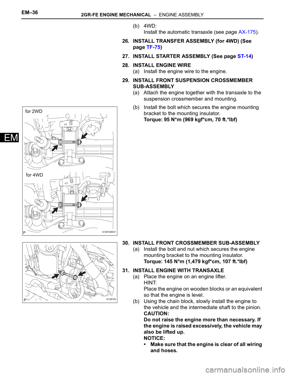
29. INSTALL FRONT SUSPENSION CROSSMEMBER
SUB-ASSEMBLY
(a) Attach the engine together with the transaxle to the
suspension crossmember and mounting.
(b) Install the bolt which secures the engine mounting
bracket to the mounting insulator.
Torque: 95 N*m (969 kgf*cm, 70 ft.*lbf)
30. INSTALL FRONT CROSSMEMBER SUB-ASSEMBLY
(a) Install the bolt and nut which secures the engine
mounting bracket to the mounting insulator.
Torque: 145 N*m (1,479 kgf*cm, 107 ft.*lbf)
31. INSTALL ENGINE WITH TRANSAXLE
(a) Place the engine on an engine lifter.
HINT:
Place the engine on wooden blocks or an equivalent
so that the engine is level.
(b) Using the chain block, slowly install the engine to
the vehicle and the intermediate shaft to the pinion.
CAUTION:
Do not raise the engine more than necessary. If
the engine is raised excessively, the vehicle may
also be lifted up.
NOTICE:
• Make sure that the engine is clear of all wiring
and hoses.
A139136E01
A139135
Page 794 of 2000

FU–422AZ-FE FUEL – FUEL TANK
FU
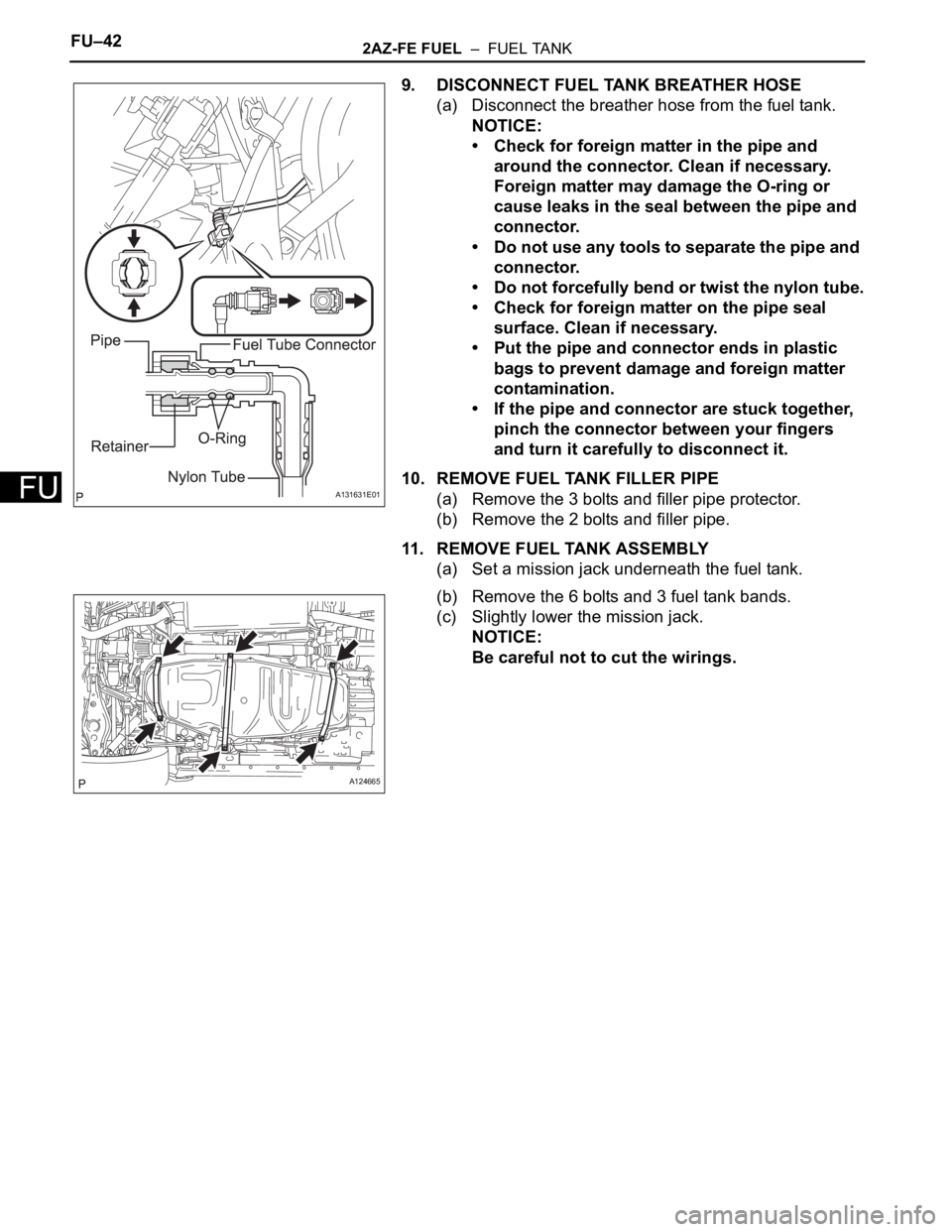
9. DISCONNECT FUEL TANK BREATHER HOSE
(a) Disconnect the breather hose from the fuel tank.
NOTICE:
• Check for foreign matter in the pipe and
around the connector. Clean if necessary.
Foreign matter may damage the O-ring or
cause leaks in the seal between the pipe and
connector.
• Do not use any tools to separate the pipe and
connector.
• Do not forcefully bend or twist the nylon tube.
• Check for foreign matter on the pipe seal
surface. Clean if necessary.
• Put the pipe and connector ends in plastic
bags to prevent damage and foreign matter
contamination.
• If the pipe and connector are stuck together,
pinch the connector between your fingers
and turn it carefully to disconnect it.
10. REMOVE FUEL TANK FILLER PIPE
(a) Remove the 3 bolts and filler pipe protector.
(b) Remove the 2 bolts and filler pipe.
11. REMOVE FUEL TANK ASSEMBLY
(a) Set a mission jack underneath the fuel tank.
(b) Remove the 6 bolts and 3 fuel tank bands.
(c) Slightly lower the mission jack.
NOTICE:
Be careful not to cut the wirings.
A131631E01
A124665
Page 798 of 2000
FU–462AZ-FE FUEL – FUEL TANK
FU
INSTALLATION
1. INSTALL FUEL TANK ASSEMBLY
(a) Set the fuel tank on a mission jack.
(b) Lift up the mission jack.
(c) Fold back the 2 cushion rubbers.
(d) Connect the fuel pump connector and sender gauge
connector to the fuel tank.
NOTICE:
Be careful not to cut the wirings.
(e) Attach the wire harness to the 4 clamps.
(f) Install the 3 fuel tank bands with the 6 bolts.
Torque: 40 N*m (408 kgf*cm, 30 ft.*lbf)
2. INSTALL FUEL TANK FILLER PIPE
(a) Install the filler pipe with the 2 bolts.
Torque: 23.5 N*m (240 kgf*cm, 17 ft.*lbf)
(b) Install the filler pipe protector with the 3 bolts.
3. CONNECT FUEL TANK TO FILLER PIPE HOSE
(a) Connect the filler pipe hose to the fuel tank.
A130491E01
A124665
A124662
Page 820 of 2000

FU–362GR-FE FUEL – FUEL TANK
FU
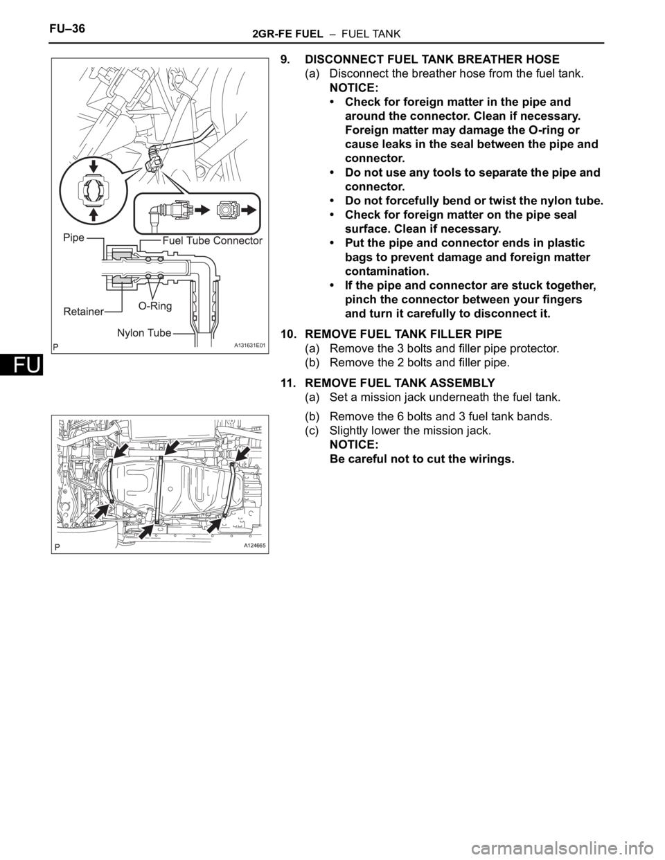
9. DISCONNECT FUEL TANK BREATHER HOSE
(a) Disconnect the breather hose from the fuel tank.
NOTICE:
• Check for foreign matter in the pipe and
around the connector. Clean if necessary.
Foreign matter may damage the O-ring or
cause leaks in the seal between the pipe and
connector.
• Do not use any tools to separate the pipe and
connector.
• Do not forcefully bend or twist the nylon tube.
• Check for foreign matter on the pipe seal
surface. Clean if necessary.
• Put the pipe and connector ends in plastic
bags to prevent damage and foreign matter
contamination.
• If the pipe and connector are stuck together,
pinch the connector between your fingers
and turn it carefully to disconnect it.
10. REMOVE FUEL TANK FILLER PIPE
(a) Remove the 3 bolts and filler pipe protector.
(b) Remove the 2 bolts and filler pipe.
11. REMOVE FUEL TANK ASSEMBLY
(a) Set a mission jack underneath the fuel tank.
(b) Remove the 6 bolts and 3 fuel tank bands.
(c) Slightly lower the mission jack.
NOTICE:
Be careful not to cut the wirings.
A131631E01
A124665
Page 824 of 2000
FU–402GR-FE FUEL – FUEL TANK
FU
INSTALLATION
1. INSTALL FUEL TANK ASSEMBLY
(a) Set the fuel tank on a mission jack.
(b) Raise the mission jack.
(c) Fold back the 2 cushion rubbers.
(d) Connect the fuel pump connector and sender gauge
connector to the fuel tank.
NOTICE:
Be careful not to cut the wirings.
(e) Attach the wire harness to the 4 clamps.
(f) Install the 3 fuel tank bands with the 6 bolts.
Torque: 40 N*m (408 kgf*cm, 30 ft.*lbf)
2. INSTALL FUEL TANK FILLER PIPE
(a) Install the filler pipe with the 2 bolts.
Torque: 23.5 N*m (240 kgf*cm, 17 ft.*lbf)
(b) Install the filler pipe protector with the 3 bolts.
3. CONNECT FUEL TANK TO FILLER PIPE HOSE
(a) Connect the filler pipe hose to the fuel tank.
A130491E01
A124665
A124662