Page 1219 of 2000
U151F AUTOMATIC TRANSAXLE – AUTOMATIC TRANSAXLE UNITAX–241
AX
NOTICE:
• Push the valve body against the accumulator
piston spring and the check ball body to
install the valve body.
• When installing the valve body to the
transaxle case, do not hold the solenoids.
• Temporarily tighten the bolts marked with (1)
in the illustration first because they are
positioning bolts.
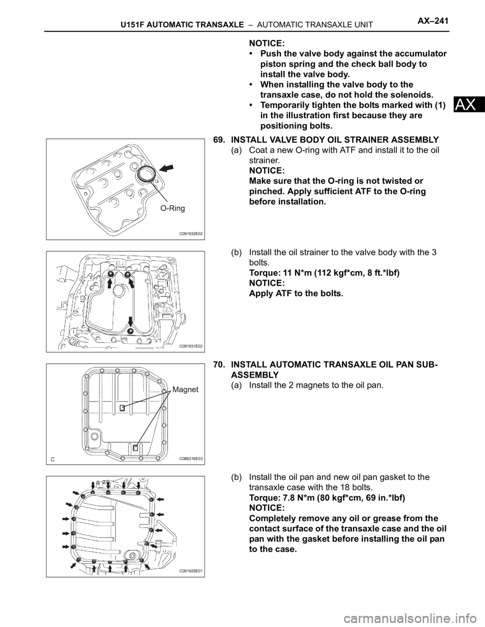
69. INSTALL VALVE BODY OIL STRAINER ASSEMBLY
(a) Coat a new O-ring with ATF and install it to the oil
strainer.
NOTICE:
Make sure that the O-ring is not twisted or
pinched. Apply sufficient ATF to the O-ring
before installation.
(b) Install the oil strainer to the valve body with the 3
bolts.
Torque: 11 N*m (112 kgf*cm, 8 ft.*lbf)
NOTICE:
Apply ATF to the bolts.
70. INSTALL AUTOMATIC TRANSAXLE OIL PAN SUB-
ASSEMBLY
(a) Install the 2 magnets to the oil pan.
(b) Install the oil pan and new oil pan gasket to the
transaxle case with the 18 bolts.
Torque: 7.8 N*m (80 kgf*cm, 69 in.*lbf)
NOTICE:
Completely remove any oil or grease from the
contact surface of the transaxle case and the oil
pan with the gasket before installing the oil pan
to the case.
C091932E02
C091931E02
C086316E03
C091925E01
Page 1220 of 2000
AX–242U151F AUTOMATIC TRANSAXLE – AUTOMATIC TRANSAXLE UNIT
AX
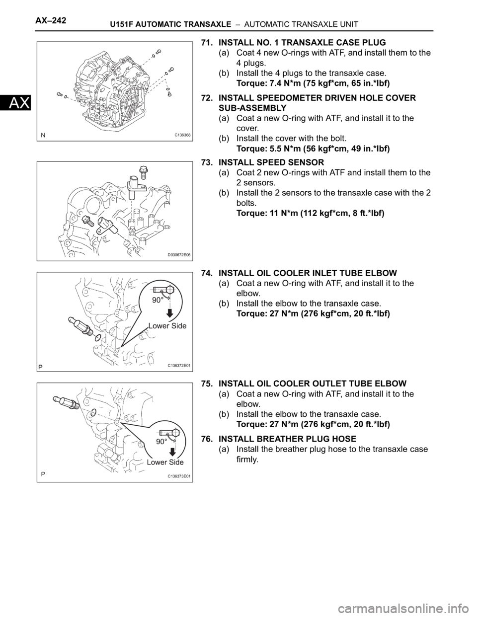
71. INSTALL NO. 1 TRANSAXLE CASE PLUG
(a) Coat 4 new O-rings with ATF, and install them to the
4 plugs.
(b) Install the 4 plugs to the transaxle case.
Torque: 7.4 N*m (75 kgf*cm, 65 in.*lbf)
72. INSTALL SPEEDOMETER DRIVEN HOLE COVER
SUB-ASSEMBLY
(a) Coat a new O-ring with ATF, and install it to the
cover.
(b) Install the cover with the bolt.
Torque: 5.5 N*m (56 kgf*cm, 49 in.*lbf)
73. INSTALL SPEED SENSOR
(a) Coat 2 new O-rings with ATF and install them to the
2 sensors.
(b) Install the 2 sensors to the transaxle case with the 2
bolts.
Torque: 11 N*m (112 kgf*cm, 8 ft.*lbf)
74. INSTALL OIL COOLER INLET TUBE ELBOW
(a) Coat a new O-ring with ATF, and install it to the
elbow.
(b) Install the elbow to the transaxle case.
Torque: 27 N*m (276 kgf*cm, 20 ft.*lbf)
75. INSTALL OIL COOLER OUTLET TUBE ELBOW
(a) Coat a new O-ring with ATF, and install it to the
elbow.
(b) Install the elbow to the transaxle case.
Torque: 27 N*m (276 kgf*cm, 20 ft.*lbf)
76. INSTALL BREATHER PLUG HOSE
(a) Install the breather plug hose to the transaxle case
firmly.
C136368
D030672E06
C136372E01
C136373E01
Page 1221 of 2000
U151F AUTOMATIC TRANSAXLE – AUTOMATIC TRANSAXLE UNITAX–243
AX
77. INSTALL PARK/NEUTRAL POSITION SWITCH
ASSEMBLY
(a) Install the switch to the manual valve shaft.
(b) Temporarily install the 2 bolts.
(c) Install a new lock washer and tighten the manual
valve shaft nut.
Torque: 5.4 N*m (55 kgf*cm, 48 in.*lbf)
(d) Temporarily install the control shaft lever.
(e) Turn the lever counterclockwise until it stops, and
then turn it clockwise 2 notches.
(f) Remove the control shaft lever.
(g) Align the groove and neutral basic line.
(h) Hold the switch in this position and tighten the 2
bolts.
Torque: 6.9 N*m (70 kgf*cm, 61 in.*lbf)
(i) Using a screwdriver, stake the nut with the lock
washer.
D009639E02
C140282
C140281
D009642E01
D009643E02
Page 1222 of 2000
AX–244U151F AUTOMATIC TRANSAXLE – AUTOMATIC TRANSAXLE UNIT
AX
(j) Install the control shaft lever with the washer and
nut.
Torque: 13 N*m (130 kgf*cm, 9 ft.*lbf)
78. INSTALL SPEEDOMETER DRIVEN HOLE COVER
SUB-ASSEMBLY
(a) Coat a new O-ring with ATF and install it to the
speedometer driven hole cover.
(b) Install the bolt and hole cover to the transaxle.
Torque: 6.9 N*m (70 kgf*cm, 61 in.*lbf)
C140280
Page 1223 of 2000
U151F AUTOMATIC TRANSAXLE – OIL PUMPAX–249
AX
REASSEMBLY
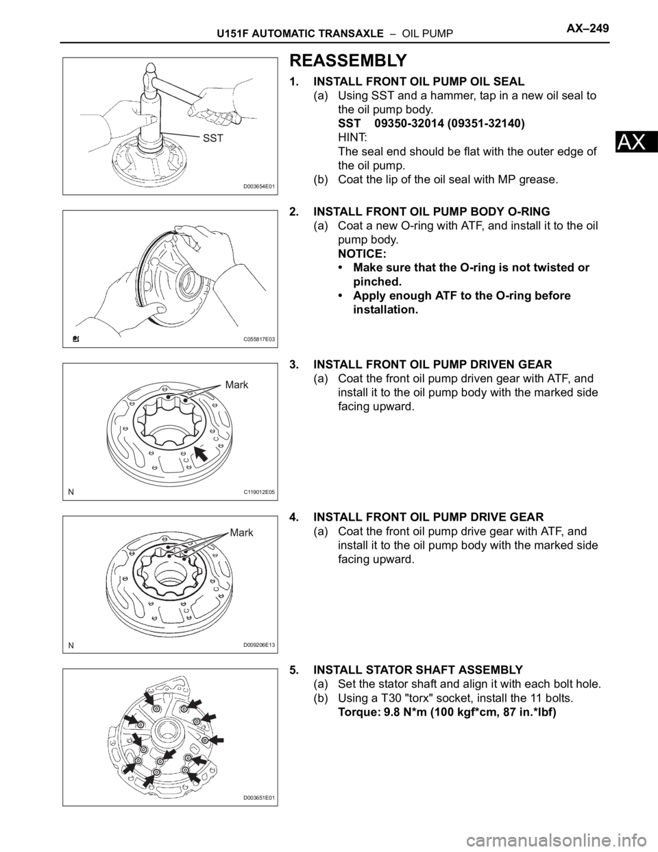
1. INSTALL FRONT OIL PUMP OIL SEAL
(a) Using SST and a hammer, tap in a new oil seal to
the oil pump body.
SST 09350-32014 (09351-32140)
HINT:
The seal end should be flat with the outer edge of
the oil pump.
(b) Coat the lip of the oil seal with MP grease.
2. INSTALL FRONT OIL PUMP BODY O-RING
(a) Coat a new O-ring with ATF, and install it to the oil
pump body.
NOTICE:
• Make sure that the O-ring is not twisted or
pinched.
• Apply enough ATF to the O-ring before
installation.
3. INSTALL FRONT OIL PUMP DRIVEN GEAR
(a) Coat the front oil pump driven gear with ATF, and
install it to the oil pump body with the marked side
facing upward.
4. INSTALL FRONT OIL PUMP DRIVE GEAR
(a) Coat the front oil pump drive gear with ATF, and
install it to the oil pump body with the marked side
facing upward.
5. INSTALL STATOR SHAFT ASSEMBLY
(a) Set the stator shaft and align it with each bolt hole.
(b) Using a T30 "torx" socket, install the 11 bolts.
Torque: 9.8 N*m (100 kgf*cm, 87 in.*lbf)
D003654E01
C055817E03
C119012E05
D009206E13
D003651E01
Page 1224 of 2000
AX–250U151F AUTOMATIC TRANSAXLE – OIL PUMP
AX
6. INSTALL CLUTCH DRUM OIL SEAL RING
(a) Coat 2 new oil seal rings with ATF.
(b) Install 2 new clutch drum oil seal rings.
NOTICE:
Do not expand the ring ends excessively.
7. INSPECT OIL PUMP ASSEMBLY (See page AX-247)
D026627E02
Page 1225 of 2000
U151F AUTOMATIC TRANSAXLE – SECOND BRAKE PISTONAX–253
AX
REASSEMBLY
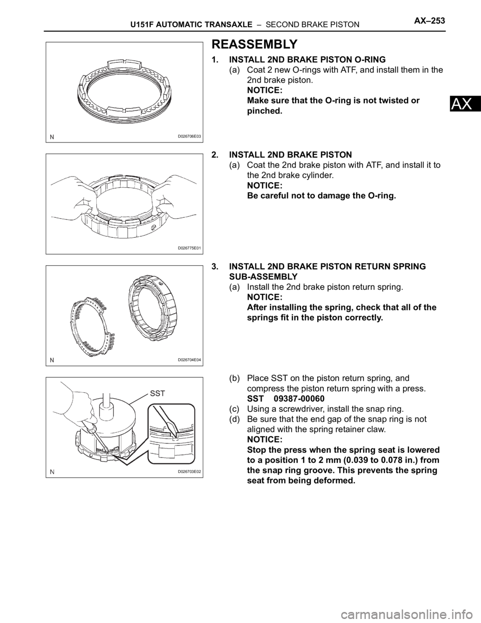
1. INSTALL 2ND BRAKE PISTON O-RING
(a) Coat 2 new O-rings with ATF, and install them in the
2nd brake piston.
NOTICE:
Make sure that the O-ring is not twisted or
pinched.
2. INSTALL 2ND BRAKE PISTON
(a) Coat the 2nd brake piston with ATF, and install it to
the 2nd brake cylinder.
NOTICE:
Be careful not to damage the O-ring.
3. INSTALL 2ND BRAKE PISTON RETURN SPRING
SUB-ASSEMBLY
(a) Install the 2nd brake piston return spring.
NOTICE:
After installing the spring, check that all of the
springs fit in the piston correctly.
(b) Place SST on the piston return spring, and
compress the piston return spring with a press.
SST 09387-00060
(c) Using a screwdriver, install the snap ring.
(d) Be sure that the end gap of the snap ring is not
aligned with the spring retainer claw.
NOTICE:
Stop the press when the spring seat is lowered
to a position 1 to 2 mm (0.039 to 0.078 in.) from
the snap ring groove. This prevents the spring
seat from being deformed.
D026706E03
D026775E01
D026704E04
D026703E02
Page 1226 of 2000
AX–256U151F AUTOMATIC TRANSAXLE – FORWARD CLUTCH
AX
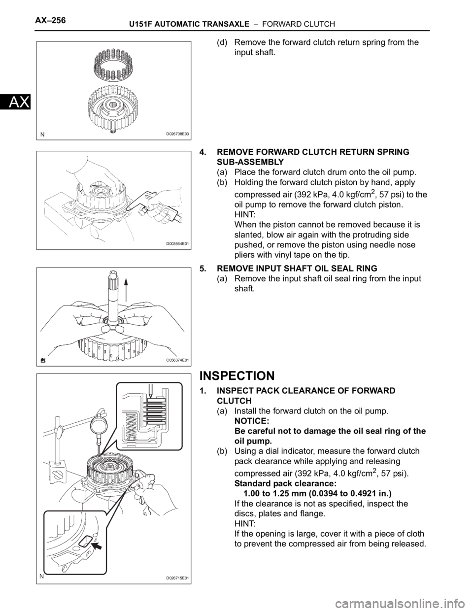
(d) Remove the forward clutch return spring from the
input shaft.
4. REMOVE FORWARD CLUTCH RETURN SPRING
SUB-ASSEMBLY
(a) Place the forward clutch drum onto the oil pump.
(b) Holding the forward clutch piston by hand, apply
compressed air (392 kPa, 4.0 kgf/cm
2, 57 psi) to the
oil pump to remove the forward clutch piston.
HINT:
When the piston cannot be removed because it is
slanted, blow air again with the protruding side
pushed, or remove the piston using needle nose
pliers with vinyl tape on the tip.
5. REMOVE INPUT SHAFT OIL SEAL RING
(a) Remove the input shaft oil seal ring from the input
shaft.
INSPECTION
1. INSPECT PACK CLEARANCE OF FORWARD
CLUTCH
(a) Install the forward clutch on the oil pump.
NOTICE:
Be careful not to damage the oil seal ring of the
oil pump.
(b) Using a dial indicator, measure the forward clutch
pack clearance while applying and releasing
compressed air (392 kPa, 4.0 kgf/cm
2, 57 psi).
Standard pack clearance:
1.00 to 1.25 mm (0.0394 to 0.4921 in.)
If the clearance is not as specified, inspect the
discs, plates and flange.
HINT:
If the opening is large, cover it with a piece of cloth
to prevent the compressed air from being released.
D026708E03
D003664E01
C056374E01
D026715E01