Page 1227 of 2000

U151F AUTOMATIC TRANSAXLE – FORWARD CLUTCHAX–257
AX
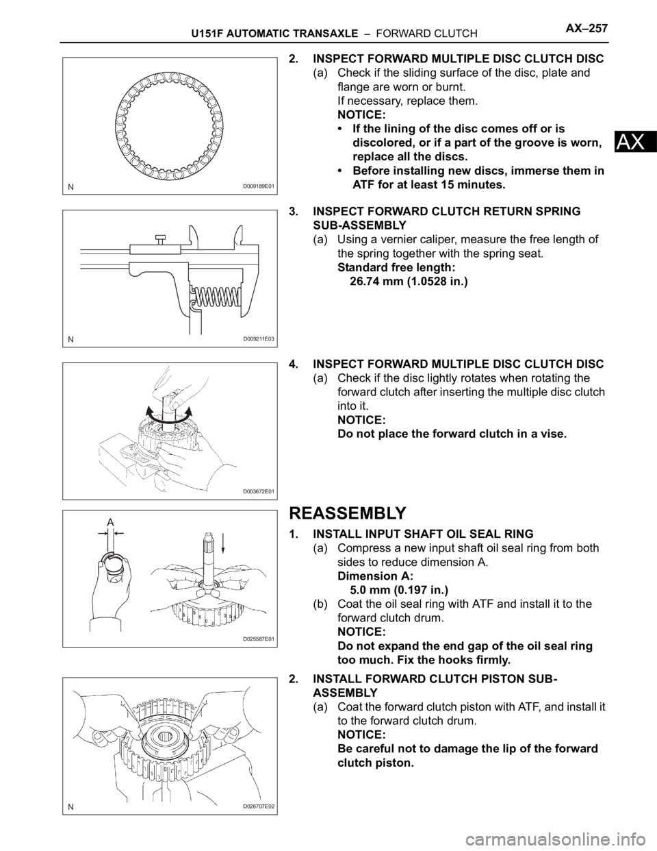
2. INSPECT FORWARD MULTIPLE DISC CLUTCH DISC
(a) Check if the sliding surface of the disc, plate and
flange are worn or burnt.
If necessary, replace them.
NOTICE:
• If the lining of the disc comes off or is
discolored, or if a part of the groove is worn,
replace all the discs.
• Before installing new discs, immerse them in
ATF for at least 15 minutes.
3. INSPECT FORWARD CLUTCH RETURN SPRING
SUB-ASSEMBLY
(a) Using a vernier caliper, measure the free length of
the spring together with the spring seat.
Standard free length:
26.74 mm (1.0528 in.)
4. INSPECT FORWARD MULTIPLE DISC CLUTCH DISC
(a) Check if the disc lightly rotates when rotating the
forward clutch after inserting the multiple disc clutch
into it.
NOTICE:
Do not place the forward clutch in a vise.
REASSEMBLY
1. INSTALL INPUT SHAFT OIL SEAL RING
(a) Compress a new input shaft oil seal ring from both
sides to reduce dimension A.
Dimension A:
5.0 mm (0.197 in.)
(b) Coat the oil seal ring with ATF and install it to the
forward clutch drum.
NOTICE:
Do not expand the end gap of the oil seal ring
too much. Fix the hooks firmly.
2. INSTALL FORWARD CLUTCH PISTON SUB-
ASSEMBLY
(a) Coat the forward clutch piston with ATF, and install it
to the forward clutch drum.
NOTICE:
Be careful not to damage the lip of the forward
clutch piston.
D009189E01
D009211E03
D003672E01
D025587E01
D026707E02
Page 1228 of 2000

AX–258U151F AUTOMATIC TRANSAXLE – FORWARD CLUTCH
AX
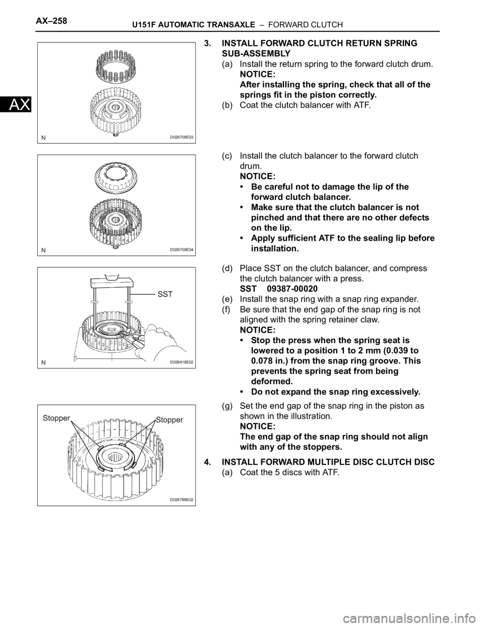
3. INSTALL FORWARD CLUTCH RETURN SPRING
SUB-ASSEMBLY
(a) Install the return spring to the forward clutch drum.
NOTICE:
After installing the spring, check that all of the
springs fit in the piston correctly.
(b) Coat the clutch balancer with ATF.
(c) Install the clutch balancer to the forward clutch
drum.
NOTICE:
• Be careful not to damage the lip of the
forward clutch balancer.
• Make sure that the clutch balancer is not
pinched and that there are no other defects
on the lip.
• Apply sufficient ATF to the sealing lip before
installation.
(d) Place SST on the clutch balancer, and compress
the clutch balancer with a press.
SST 09387-00020
(e) Install the snap ring with a snap ring expander.
(f) Be sure that the end gap of the snap ring is not
aligned with the spring retainer claw.
NOTICE:
• Stop the press when the spring seat is
lowered to a position 1 to 2 mm (0.039 to
0.078 in.) from the snap ring groove. This
prevents the spring seat from being
deformed.
• Do not expand the snap ring excessively.
(g) Set the end gap of the snap ring in the piston as
shown in the illustration.
NOTICE:
The end gap of the snap ring should not align
with any of the stoppers.
4. INSTALL FORWARD MULTIPLE DISC CLUTCH DISC
(a) Coat the 5 discs with ATF.
D026708E03
D026709E04
D026418E02
D026788E02
Page 1229 of 2000

U151F AUTOMATIC TRANSAXLE – FORWARD CLUTCHAX–259
AX
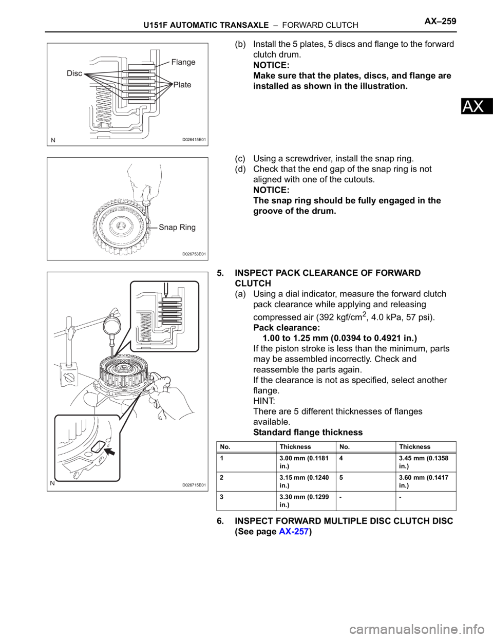
(b) Install the 5 plates, 5 discs and flange to the forward
clutch drum.
NOTICE:
Make sure that the plates, discs, and flange are
installed as shown in the illustration.
(c) Using a screwdriver, install the snap ring.
(d) Check that the end gap of the snap ring is not
aligned with one of the cutouts.
NOTICE:
The snap ring should be fully engaged in the
groove of the drum.
5. INSPECT PACK CLEARANCE OF FORWARD
CLUTCH
(a) Using a dial indicator, measure the forward clutch
pack clearance while applying and releasing
compressed air (392 kgf/cm
2, 4.0 kPa, 57 psi).
Pack clearance:
1.00 to 1.25 mm (0.0394 to 0.4921 in.)
If the piston stroke is less than the minimum, parts
may be assembled incorrectly. Check and
reassemble the parts again.
If the clearance is not as specified, select another
flange.
HINT:
There are 5 different thicknesses of flanges
available.
Standard flange thickness
6. INSPECT FORWARD MULTIPLE DISC CLUTCH DISC
(See page AX-257)
D026415E01
D026753E01
D026715E01
No. Thickness No. Thickness
1 3.00 mm (0.1181
in.)4 3.45 mm (0.1358
in.)
2 3.15 mm (0.1240
in.)5 3.60 mm (0.1417
in.)
3 3.30 mm (0.1299
in.)--
Page 1230 of 2000
AX–6U241E AUTOMATIC TRANSAXLE – AUTOMATIC TRANSAXLE SYSTEM
AX
SYSTEM DIAGRAM
The configuration of the electronic control system in the
U241E automatic transaxle is as shown in the following chart.
C127635E02
Page 1231 of 2000
U241E AUTOMATIC TRANSAXLE – AUTOMATIC TRANSAXLE SYSTEMAX–7
AX
C116585E02
Page 1232 of 2000
AX–8U241E AUTOMATIC TRANSAXLE – AUTOMATIC TRANSAXLE SYSTEM
AX
C132118E02
Page 1233 of 2000
U241E AUTOMATIC TRANSAXLE – AUTOMATIC TRANSAXLE SYSTEMAX–9
AX
C132119E01
Page 1234 of 2000
AX–10U241E AUTOMATIC TRANSAXLE – AUTOMATIC TRANSAXLE SYSTEM
AX
SYSTEM DESCRIPTION
1. SYSTEM DESCRIPTION
(a) The Electronic Controlled Automatic Transaxle
(ECT) is an automatic transaxle that electronically
controls shift timing using the Engine Control
Module (ECM). The ECM detects electrical signals
that indicate engine and driving conditions, and
controls the shift point based on driver habits and
road conditions. As a result, fuel efficiency and
power transaxle performance are improved.
Shift shock is reduced by controlling the engine and
transaxle simultaneously.
In addition, the ECT has the following features:
• Diagnostic function.
• Fail-safe function when a malfunction occurs.