2006 TOYOTA RAV4 sensor
[x] Cancel search: sensorPage 1652 of 2000
AC–24AIR CONDITIONING – AIR CONDITIONING SYSTEM (for Automatic Air Conditioning Sys-
tem)
AC
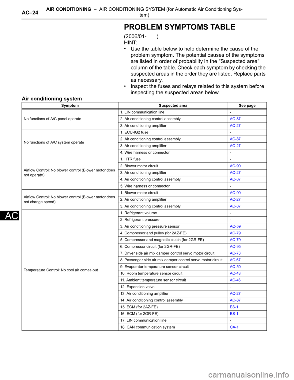
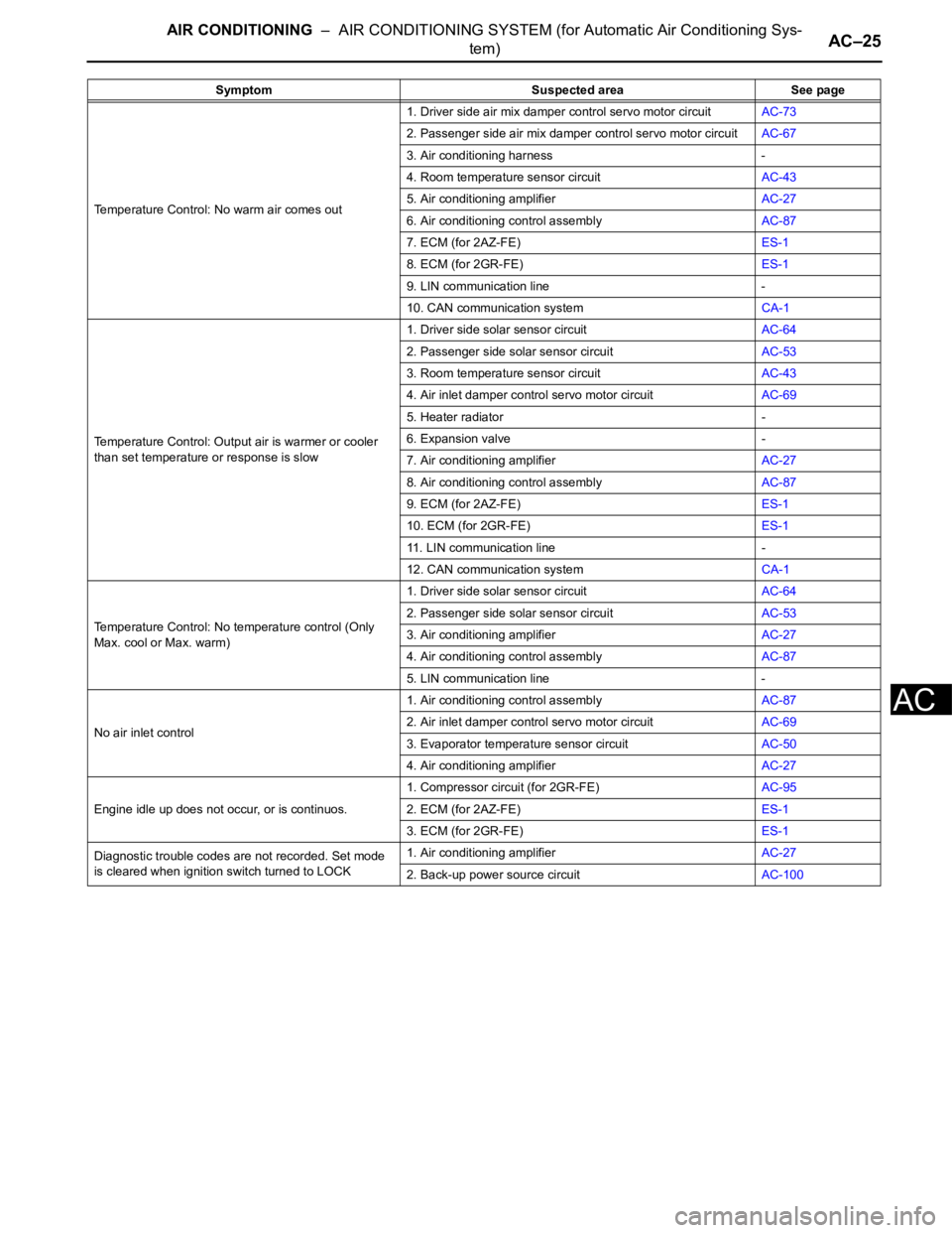
PROBLEM SYMPTOMS TABLE
(2006/01- )
HINT:
• Use the table below to help determine the cause of the
problem symptom. The potential causes of the symptoms
are listed in order of probability in the "Suspected area"
column of the table. Check each symptom by checking the
suspected areas in the order they are listed. Replace parts
as necessary.
• Inspect the fuses and relays related to this system before
inspecting the suspected areas below.
Air conditioning system
Symptom Suspected area See page
No functions of A/C panel operate1. LIN communication line -
2. Air conditioning control assemblyAC-87
3. Air conditioning amplifierAC-27
No functions of A/C system operate1. ECU-IG2 fuse -
2. Air conditioning control assemblyAC-87
3. Air conditioning amplifierAC-27
4. Wire harness or connector -
Airflow Control: No blower control (Blower motor does
not operate)1. HTR fuse -
2. Blower motor circuitAC-90
3. Air conditioning amplifierAC-27
4. Air conditioning control assemblyAC-87
5. Wire harness or connector -
Airflow Control: No blower control (Blower motor does
not change speed)1. Blower motor circuitAC-90
2. Air conditioning amplifierAC-27
3. Air conditioning control assemblyAC-87
Temperature Control: No cool air comes out1. Refrigerant volume -
2. Refrigerant pressure -
3. Air conditioning pressure sensorAC-59
4. Compressor and pulley (for 2AZ-FE)AC-79
5. Compressor and magnetic clutch (for 2GR-FE)AC-79
6. Compressor circuit (for 2GR-FE)AC-95
7. Driver side air mix damper control servo motor circuitAC-73
8. Passenger side air mix damper control servo motor circuitAC-67
9. Evaporator temperature sensor circuitAC-50
10. Room temperature sensor circuitAC-43
11. Ambient temperature sensor circuitAC-46
12. Expansion valve -
13. Air conditioning amplifierAC-27
14. Air conditioning control assemblyAC-87
15. ECM (for 2AZ-FE)ES-1
16. ECM (for 2GR-FE)ES-1
17. LIN communication line -
18. CAN communication systemCA-1
Page 1653 of 2000
AIR CONDITIONING – AIR CONDITIONING SYSTEM (for Automatic Air Conditioning Sys-
tem)AC–25
AC
Temperature Control: No warm air comes out1. Driver side air mix damper control servo motor circuitAC-73
2. Passenger side air mix damper control servo motor circuitAC-67
3. Air conditioning harness -
4. Room temperature sensor circuitAC-43
5. Air conditioning amplifierAC-27
6. Air conditioning control assemblyAC-87
7. ECM (for 2AZ-FE)ES-1
8. ECM (for 2GR-FE)ES-1
9. LIN communication line -
10. CAN communication systemCA-1
Temperature Control: Output air is warmer or cooler
than set temperature or response is slow1. Driver side solar sensor circuitAC-64
2. Passenger side solar sensor circuitAC-53
3. Room temperature sensor circuitAC-43
4. Air inlet damper control servo motor circuitAC-69
5. Heater radiator -
6. Expansion valve -
7. Air conditioning amplifierAC-27
8. Air conditioning control assemblyAC-87
9. ECM (for 2AZ-FE)ES-1
10. ECM (for 2GR-FE)ES-1
11. LIN communication line -
12. CAN communication systemCA-1
Temperature Control: No temperature control (Only
Max. cool or Max. warm)1. Driver side solar sensor circuitAC-64
2. Passenger side solar sensor circuitAC-53
3. Air conditioning amplifierAC-27
4. Air conditioning control assemblyAC-87
5. LIN communication line -
No air inlet control1. Air conditioning control assemblyAC-87
2. Air inlet damper control servo motor circuitAC-69
3. Evaporator temperature sensor circuitAC-50
4. Air conditioning amplifierAC-27
Engine idle up does not occur, or is continuos.1. Compressor circuit (for 2GR-FE)AC-95
2. ECM (for 2AZ-FE)ES-1
3. ECM (for 2GR-FE)ES-1
Diagnostic trouble codes are not recorded. Set mode
is cleared when ignition switch turned to LOCK1. Air conditioning amplifierAC-27
2. Back-up power source circuitAC-100 Symptom Suspected area See page
Page 1654 of 2000
AC–26AIR CONDITIONING – AIR CONDITIONING SYSTEM (for Automatic Air Conditioning Sys-
tem)
AC
TERMINALS OF ECU
(2005/11-2006/01)
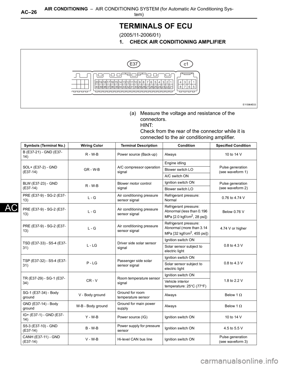
1. CHECK AIR CONDITIONING AMPLIFIER
(a) Measure the voltage and resistance of the
connectors.
HINT:
Check from the rear of the connector while it is
connected to the air conditioning amplifier.
E115964E03
Symbols (Terminal No.) Wiring Color Terminal Description ConditionSpecified Condition
B (E37-21) - GND (E37-
14)R - W-B Power source (Back-up) Always 10 to 14 V
SOL+ (E37-2) - GND
(E37-14)GR - W-BA/C compressor operation
signalEngine idling
Pulse generation
(see waveform 1) Blower switch LO
A/C switch ON
BLW (E37-23) - GND
(E37-14)R - W-BBlower motor control
signalIgnition switch ON
Pulse generation
(see waveform 2)
Blower switch LO
PRE (E37-9) - SG-2 (E37-
13)L - GAir conditioning pressure
sensor signalRefrigerant pressure:
Normal0.76 to 4.74 V
PRE (E37-9) - SG-2 (E37-
13)L - GAir conditioning pressure
sensor signalRefrigerant pressure:
Abnormal (less than 0.196
MPa [2.0 kgf/cm
2, 28 psi]) Below 0.76 V
PRE (E37-9) - SG-2 (E37-
13)L - GAir conditioning pressure
sensor signalRefrigerant pressure:
Abnormal (more than 3.14
MPa [32 kgf/cm
2, 455 psi])4.74 V or higher
TSD (E37-33) - S5-4 (E37-
31)L - LGDriver side solar sensor
signalIgnition switch ON
0.8 to 4.3 V
Solar sensor subject to
electric light
TSP (E37-32) - S5-4 (E37-
31)P - LGPassenger side solar
sensor signalIgnition switch ON
0.8 to 4.3 V
Solar sensor subject to
electric light
TR (E37-29) - SG-1 (E37-
34)CR - VRoom temperature sensor
signalIgnition switch ON
1.8 to 2.2 V
Vehicle interior
temperature: 25
C (77F)
SG-1 (E37-34) - Body
groundV - Body groundGround for room
temperature sensorAlways Below 1
GND (E37-14) - Body
groundW-B - Body groundGround for main power
supplyAlways Below 1
IG+ (E37-1) - GND (E37-
14)Y - W-B Power source (IG) Ignition switch ON 10 to 14 V
S5-3 (E37-10) - GND
(E37-14)B - W-BPower supply for pressure
sensorIgnition switch ON 4.5 to 5.5 V
CANH (E37-11) - GND
(E37-14)V - W-B Hi-level CAN bus line Ignition switch ONPulse generation
(see waveform 3)
Page 1655 of 2000
AIR CONDITIONING – AIR CONDITIONING SYSTEM (for Automatic Air Conditioning Sys-
tem)AC–27
AC
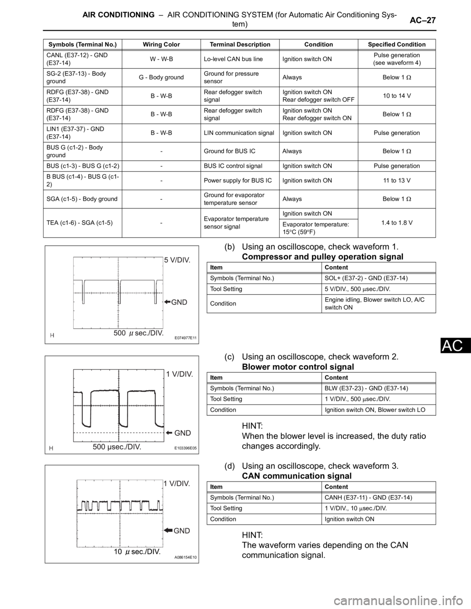
(b) Using an oscilloscope, check waveform 1.
Compressor and pulley operation signal
(c) Using an oscilloscope, check waveform 2.
Blower motor control signal
HINT:
When the blower level is increased, the duty ratio
changes accordingly.
(d) Using an oscilloscope, check waveform 3.
CAN communication signal
HINT:
The waveform varies depending on the CAN
communication signal.
CANL (E37-12) - GND
(E37-14)W - W-B Lo-level CAN bus line Ignition switch ONPulse generation
(see waveform 4)
SG-2 (E37-13) - Body
groundG - Body groundGround for pressure
sensorAlways Below 1
RDFG (E37-38) - GND
(E37-14)B - W-BRear defogger switch
signalIgnition switch ON
Rear defogger switch OFF10 to 14 V
RDFG (E37-38) - GND
(E37-14)B - W-BRear defogger switch
signalIgnition switch ON
Rear defogger switch ONBelow 1
LIN1 (E37-37) - GND
(E37-14)B - W-B LIN communication signalIgnition switch ON Pulse generation
BUS G (c1-2) - Body
ground- Ground for BUS IC Always Below 1
BUS (c1-3) - BUS G (c1-2) - BUS IC control signal Ignition switch ON Pulse generation
B BUS (c1-4) - BUS G (c1-
2)- Power supply for BUS IC Ignition switch ON 11 to 13 V
SGA (c1-5) - Body ground -Ground for evaporator
temperature sensorAlways Below 1
TEA (c1-6) - SGA (c1-5) -Evaporator temperature
sensor signalIgnition switch ON
1.4 to 1.8 V
Evaporator temperature:
15
C (59F) Symbols (Terminal No.) Wiring Color Terminal Description ConditionSpecified Condition
E074977E11
Item Content
Symbols (Terminal No.) SOL+ (E37-2) - GND (E37-14)
Tool Setting 5 V/DIV., 500
sec./DIV.
ConditionEngine idling, Blower switch LO, A/C
switch ON
E103396E05
Item Content
Symbols (Terminal No.) BLW (E37-23) - GND (E37-14)
Tool Setting 1 V/DIV., 500
sec./DIV.
Condition Ignition switch ON, Blower switch LO
A086154E10
Item Content
Symbols (Terminal No.) CANH (E37-11) - GND (E37-14)
Tool Setting 1 V/DIV., 10
sec./DIV.
Condition Ignition switch ON
Page 1657 of 2000
AIR CONDITIONING – AIR CONDITIONING SYSTEM (for Automatic Air Conditioning Sys-
tem)AC–29
AC
TERMINALS OF ECU
(2006/01- )
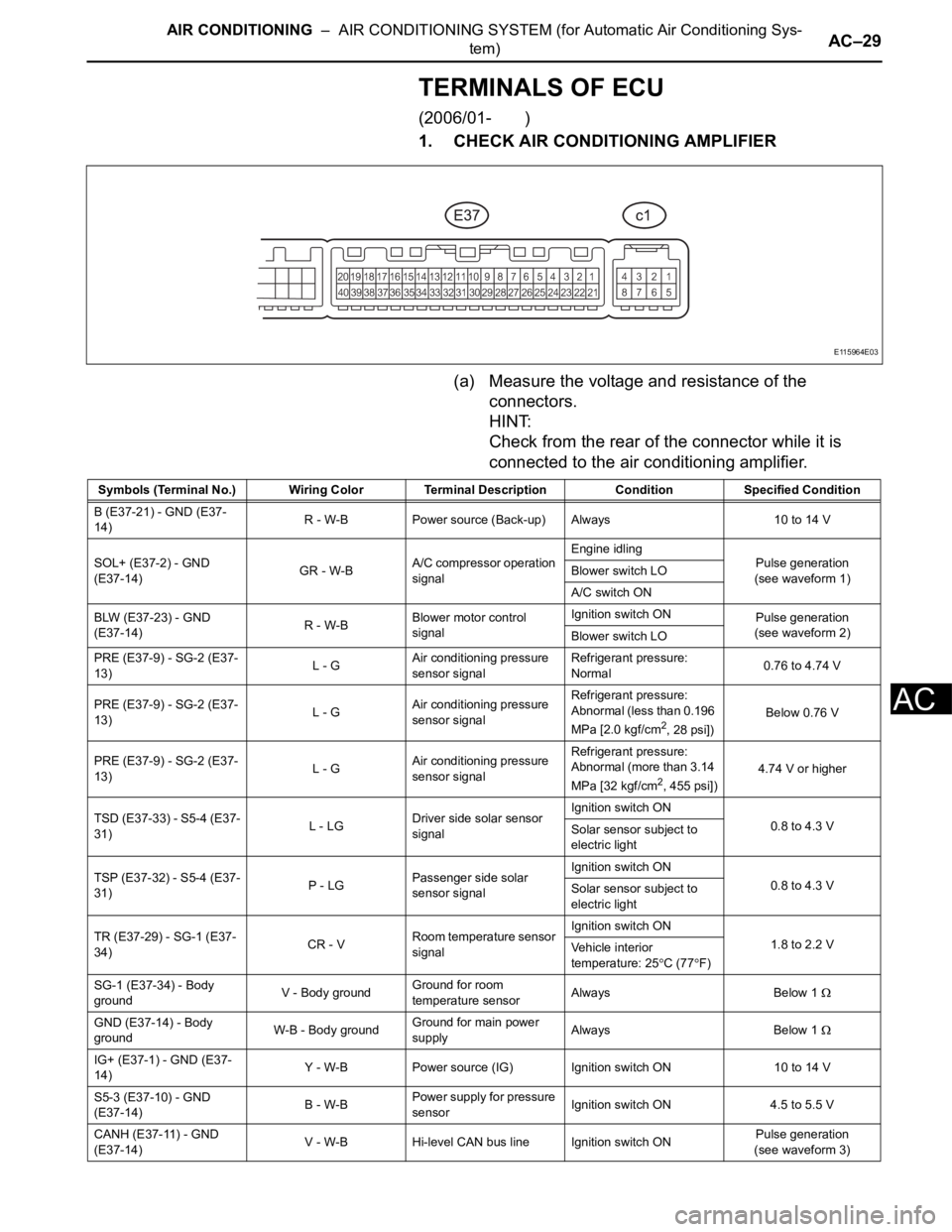
1. CHECK AIR CONDITIONING AMPLIFIER
(a) Measure the voltage and resistance of the
connectors.
HINT:
Check from the rear of the connector while it is
connected to the air conditioning amplifier.
E115964E03
Symbols (Terminal No.) Wiring Color Terminal Description ConditionSpecified Condition
B (E37-21) - GND (E37-
14)R - W-B Power source (Back-up) Always 10 to 14 V
SOL+ (E37-2) - GND
(E37-14)GR - W-BA/C compressor operation
signalEngine idling
Pulse generation
(see waveform 1) Blower switch LO
A/C switch ON
BLW (E37-23) - GND
(E37-14)R - W-BBlower motor control
signalIgnition switch ON
Pulse generation
(see waveform 2)
Blower switch LO
PRE (E37-9) - SG-2 (E37-
13)L - GAir conditioning pressure
sensor signalRefrigerant pressure:
Normal0.76 to 4.74 V
PRE (E37-9) - SG-2 (E37-
13)L - GAir conditioning pressure
sensor signalRefrigerant pressure:
Abnormal (less than 0.196
MPa [2.0 kgf/cm
2, 28 psi]) Below 0.76 V
PRE (E37-9) - SG-2 (E37-
13)L - GAir conditioning pressure
sensor signalRefrigerant pressure:
Abnormal (more than 3.14
MPa [32 kgf/cm
2, 455 psi])4.74 V or higher
TSD (E37-33) - S5-4 (E37-
31)L - LGDriver side solar sensor
signalIgnition switch ON
0.8 to 4.3 V
Solar sensor subject to
electric light
TSP (E37-32) - S5-4 (E37-
31)P - LGPassenger side solar
sensor signalIgnition switch ON
0.8 to 4.3 V
Solar sensor subject to
electric light
TR (E37-29) - SG-1 (E37-
34)CR - VRoom temperature sensor
signalIgnition switch ON
1.8 to 2.2 V
Vehicle interior
temperature: 25
C (77F)
SG-1 (E37-34) - Body
groundV - Body groundGround for room
temperature sensorAlways Below 1
GND (E37-14) - Body
groundW-B - Body groundGround for main power
supplyAlways Below 1
IG+ (E37-1) - GND (E37-
14)Y - W-B Power source (IG) Ignition switch ON 10 to 14 V
S5-3 (E37-10) - GND
(E37-14)B - W-BPower supply for pressure
sensorIgnition switch ON 4.5 to 5.5 V
CANH (E37-11) - GND
(E37-14)V - W-B Hi-level CAN bus line Ignition switch ONPulse generation
(see waveform 3)
Page 1658 of 2000
AC–30AIR CONDITIONING – AIR CONDITIONING SYSTEM (for Automatic Air Conditioning Sys-
tem)
AC
HINT:
*: for 2GR-FE
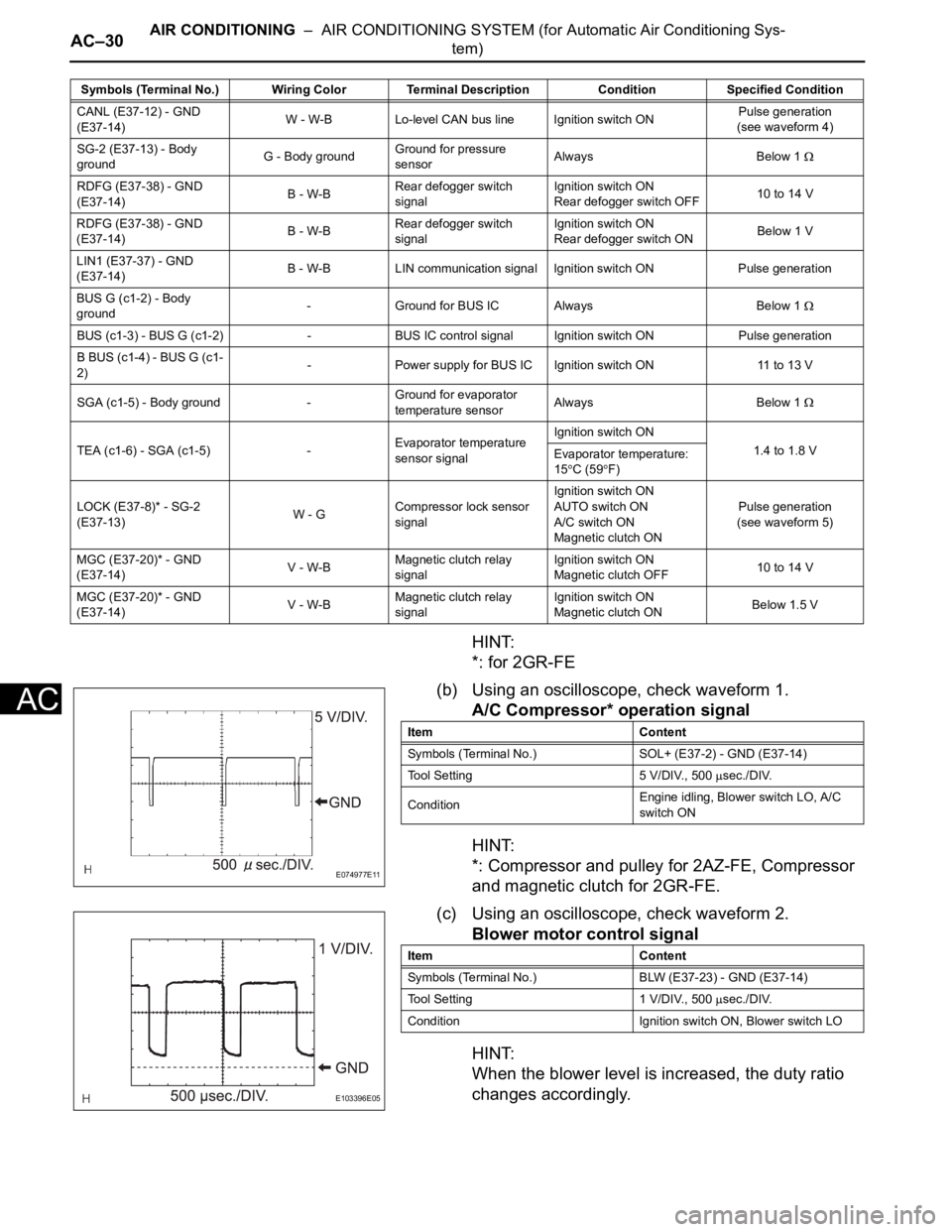
(b) Using an oscilloscope, check waveform 1.
A/C Compressor* operation signal
HINT:
*: Compressor and pulley for 2AZ-FE, Compressor
and magnetic clutch for 2GR-FE.
(c) Using an oscilloscope, check waveform 2.
Blower motor control signal
HINT:
When the blower level is increased, the duty ratio
changes accordingly.
CANL (E37-12) - GND
(E37-14)W - W-B Lo-level CAN bus line Ignition switch ONPulse generation
(see waveform 4)
SG-2 (E37-13) - Body
groundG - Body groundGround for pressure
sensorAlways Below 1
RDFG (E37-38) - GND
(E37-14)B - W-BRear defogger switch
signalIgnition switch ON
Rear defogger switch OFF10 to 14 V
RDFG (E37-38) - GND
(E37-14)B - W-BRear defogger switch
signalIgnition switch ON
Rear defogger switch ONBelow 1 V
LIN1 (E37-37) - GND
(E37-14)B - W-B LIN communication signal Ignition switch ON Pulse generation
BUS G (c1-2) - Body
ground- Ground for BUS IC Always Below 1
BUS (c1-3) - BUS G (c1-2) - BUS IC control signal Ignition switch ON Pulse generation
B BUS (c1-4) - BUS G (c1-
2)- Power supply for BUS IC Ignition switch ON 11 to 13 V
SGA (c1-5) - Body ground -Ground for evaporator
temperature sensorAlways Below 1
TEA (c1-6) - SGA (c1-5) -Evaporator temperature
sensor signalIgnition switch ON
1.4 to 1.8 V
Evaporator temperature:
15
C (59F)
LOCK (E37-8)* - SG-2
(E37-13)W - GCompressor lock sensor
signalIgnition switch ON
AUTO switch ON
A/C switch ON
Magnetic clutch ONPulse generation
(see waveform 5)
MGC (E37-20)* - GND
(E37-14)V - W-BMagnetic clutch relay
signalIgnition switch ON
Magnetic clutch OFF10 to 14 V
MGC (E37-20)* - GND
(E37-14)V - W-BMagnetic clutch relay
signalIgnition switch ON
Magnetic clutch ONBelow 1.5 V Symbols (Terminal No.) Wiring Color Terminal Description ConditionSpecified Condition
E074977E11
Item Content
Symbols (Terminal No.) SOL+ (E37-2) - GND (E37-14)
Tool Setting 5 V/DIV., 500
sec./DIV.
ConditionEngine idling, Blower switch LO, A/C
switch ON
E103396E05
Item Content
Symbols (Terminal No.) BLW (E37-23) - GND (E37-14)
Tool Setting 1 V/DIV., 500
sec./DIV.
Condition Ignition switch ON, Blower switch LO
Page 1659 of 2000
AIR CONDITIONING – AIR CONDITIONING SYSTEM (for Automatic Air Conditioning Sys-
tem)AC–31
AC
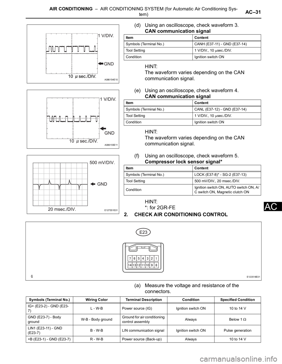
(d) Using an oscilloscope, check waveform 3.
CAN communication signal
HINT:
The waveform varies depending on the CAN
communication signal.
(e) Using an oscilloscope, check waveform 4.
CAN communication signal
HINT:
The waveform varies depending on the CAN
communication signal.
(f) Using an oscilloscope, check waveform 5.
Compressor lock sensor signal*
HINT:
*: for 2GR-FE
2. CHECK AIR CONDITIONING CONTROL
(a) Measure the voltage and resistance of the
connectors.
A086154E10
Item Content
Symbols (Terminal No.) CANH (E37-11) - GND (E37-14)
Tool Setting 1 V/DIV., 10
sec./DIV.
Condition Ignition switch ON
A086155E11
Item Content
Symbols (Terminal No.) CANL (E37-12) - GND (E37-14)
Tool Setting 1 V/DIV., 10
sec./DIV.
Condition Ignition switch ON
E127551E01
Item Content
Symbols (Terminal No.) LOCK (E37-8)* - SG-2 (E37-13)
Tool Setting 500 mV/DIV., 20 msec./DIV.
ConditionIgnition switch ON, AUTO switch ON, A/
C switch ON, Magnetic clutch ON
E123518E01
Symbols (Terminal No.) Wiring Color Terminal Description ConditionSpecified Condition
IG+ (E23-2) - GND (E23-
7)L - W-B Power source (IG) Ignition switch ON 10 to 14 V
GND (E23-7) - Body
groundW-B - Body groundGround for air conditioning
control assemblyAlways Below 1
LIN1 (E23-11) - GND
(E23-7)B - W-B LIN communication signalIgnition switch ON Pulse generation
+B (E23-1) - GND (E23-7) R - W-B Power source (Back-up) Always 10 to 14 V
Page 1670 of 2000

AIR CONDITIONING – ROOM TEMPERATURE SENSOR (for Automatic Air Conditioning
System)AC–231
AC
INSTALLATION
1. INSTALL ROOM TEMPERATURE SENSOR
(a) Attach the claws to install the sensor.
(b) Connect the connector.
(c) Connect the duct.
2. INSTALL LOWER INSTRUMENT PANEL
(a) Install the lower instrument panel (see page IP-23).