Page 1629 of 2000
POWER STEERING – ELECTRONIC POWER STEERING SYSTEMPS–29
PS
DESCRIPTION
INSPECTION PROCEDURE
If the power steering ECU detects these DTCs, it will shut off the motor relay circuit (built into the power
steering ECU) and stop power assist. However, power assist continues if DTC C1533 is output.
(a) Check for DTC.
OK:
DTC is not output.
OK
NG
DTC C1531/25 ECU Malfunction
DTC C1532/25 ECU Malfunction
DTC C1533/25 Temperature Sensor Circuit is Low or High
DTC C1534/25 EEPROM Malfunction
DTC No. DTC Detection Condition Trouble Area
C1531/25 ECU internal malfunction (CPU malfunction) Power steering ECU
C1532/25 ECU internal malfunction (Peripheral circuit
malfunction)Power steering ECU
C1533/25 ECU internal malfunction (Substrate
temperature sensor malfunction)Power steering ECU
C1534/25 ECU internal malfunction (EEPROM error) Power steering ECU
1RECONFIRM DTC
PROCEED TO NEXT CIRCUIT INSPECTION
SHOWN IN PROBLEM SYMPTOMS TABLE
REPLACE POWER STEERING ECU
Page 1641 of 2000

AIR CONDITIONING – AIR CONDITIONING SYSTEM (for Automatic Air Conditioning Sys-
tem)AC–13
AC
SYSTEM DESCRIPTION
1. GENERAL
(a) The air conditioning system has the following
features:
• In accordance with the temperature set using the
temperature control switch, the air conditioning
amplifier determines the outlet temperature
based on the input signals from various sensors.
In addition, corrections are made in accordance
with the signals from the water temperature
sensor to control the outlet air temperature.
• Controls the blower motor in accordance with the
airflow volume determined by the air conditioning
amplifier based on the input signals from various
sensors.
• Automatically changes the outlets in accordance
with the outlet mode ratio that is determined by
the air conditioning amplifier based on the input
signals from various sensors.
• Based on the signals from the ambient
temperature sensor, this system calculates the
outside temperature and indicates it in the multi-
information display in the combination meter
assembly.
• The left/right independent temperature control
and neural network control make air conditioner
control available to suit the persons in the driver
seat and in the passenger seat.
• Turns the rear defogger and outside rear mirror
heaters on for 15 minutes when the rear
defogger switch is pressed. Turns them off if the
switch is pressed while they are operating.
• Checks the sensors in accordance with the
operation of the air conditioner switches.
• The air conditioning amplifier has the function of
controlling the indicator lighting.
Page 1645 of 2000

AIR CONDITIONING – AIR CONDITIONING SYSTEM (for Automatic Air Conditioning Sys-
tem)AC–17
AC
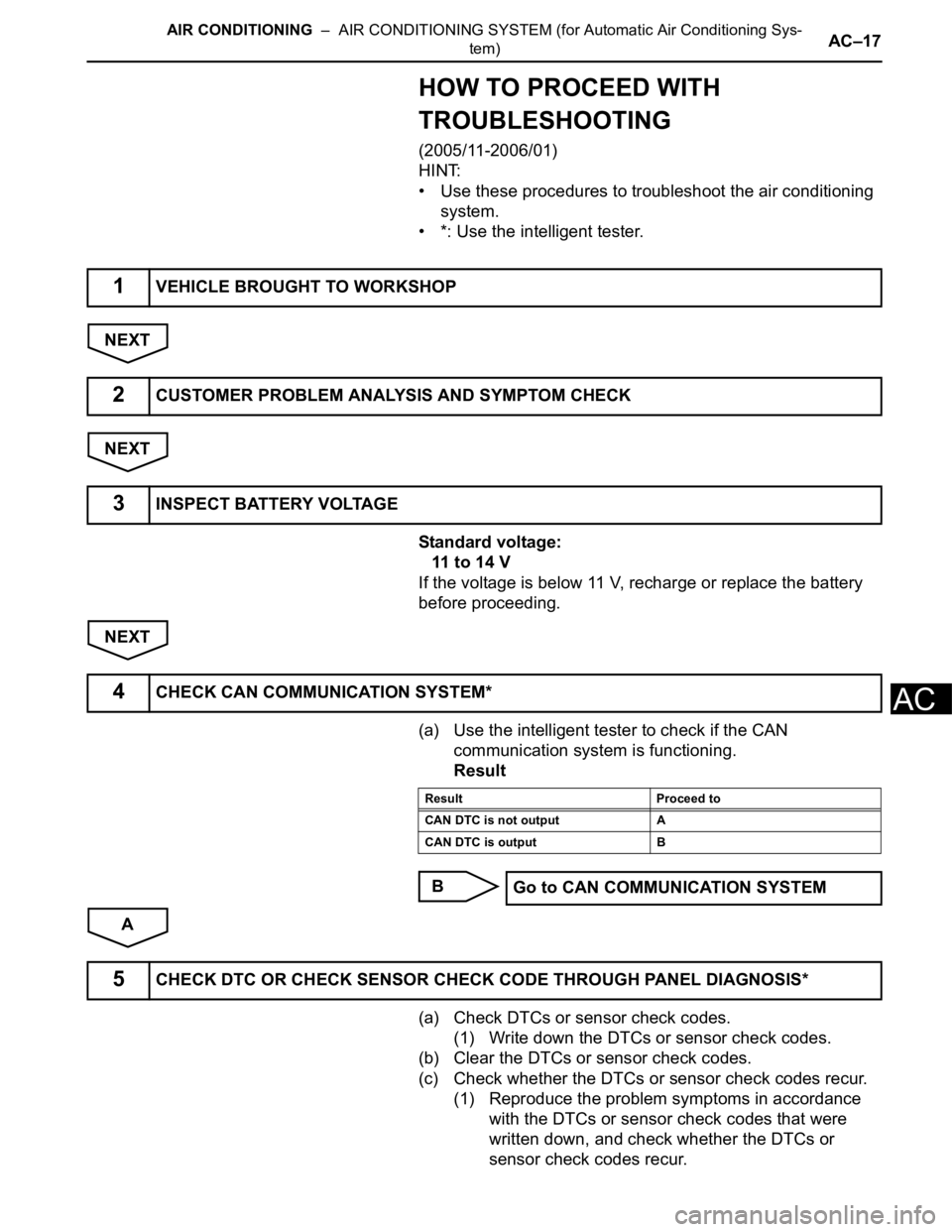
HOW TO PROCEED WITH
TROUBLESHOOTING
(2005/11-2006/01)
HINT:
• Use these procedures to troubleshoot the air conditioning
system.
• *: Use the intelligent tester.
NEXT
NEXT
Standard voltage:
11 to 14 V
If the voltage is below 11 V, recharge or replace the battery
before proceeding.
NEXT
(a) Use the intelligent tester to check if the CAN
communication system is functioning.
Result
B
A
(a) Check DTCs or sensor check codes.
(1) Write down the DTCs or sensor check codes.
(b) Clear the DTCs or sensor check codes.
(c) Check whether the DTCs or sensor check codes recur.
(1) Reproduce the problem symptoms in accordance
with the DTCs or sensor check codes that were
written down, and check whether the DTCs or
sensor check codes recur.
1VEHICLE BROUGHT TO WORKSHOP
2CUSTOMER PROBLEM ANALYSIS AND SYMPTOM CHECK
3INSPECT BATTERY VOLTAGE
4CHECK CAN COMMUNICATION SYSTEM*
Result Proceed to
CAN DTC is not output A
CAN DTC is output B
Go to CAN COMMUNICATION SYSTEM
5CHECK DTC OR CHECK SENSOR CHECK CODE THROUGH PANEL DIAGNOSIS*
Page 1646 of 2000
AC–18AIR CONDITIONING – AIR CONDITIONING SYSTEM (for Automatic Air Conditioning Sys-
tem)
AC
HINT:
Refer to the DTC chart when any DTCs or sensor
check codes are output.
Result
B
A
Result
B
A
(a) DATA LIST / ACTIVE TEST (see page AC-34)
(b) Panel diagnosis (indicator check) (see page AC-31)
(c) Panel diagnosis (actuator check) (see page AC-31)
(d) Panel diagnosis (sensor check) (see page AC-31)
(e) Terminals of ECU (see page AC-24)
NEXT
NEXT
NEXT
Result Proceed to
DTC or sensor check code is not
outputA
DTC or sensor check code is output B
Go to step 8
6REFER TO PROBLEM SYMPTOMS TABLE
Result Proceed to
Fault not listed in problem
symptoms tableA
Fault listed in problem symptoms
tableB
Go to step 8
7OVERALL ANALYSIS AND TROUBLESHOOTING*
8ADJUST, REPAIR OR REPLACE
9CONFIRMATION TEST
END
Page 1647 of 2000

AIR CONDITIONING – AIR CONDITIONING SYSTEM (for Automatic Air Conditioning Sys-
tem)AC–19
AC
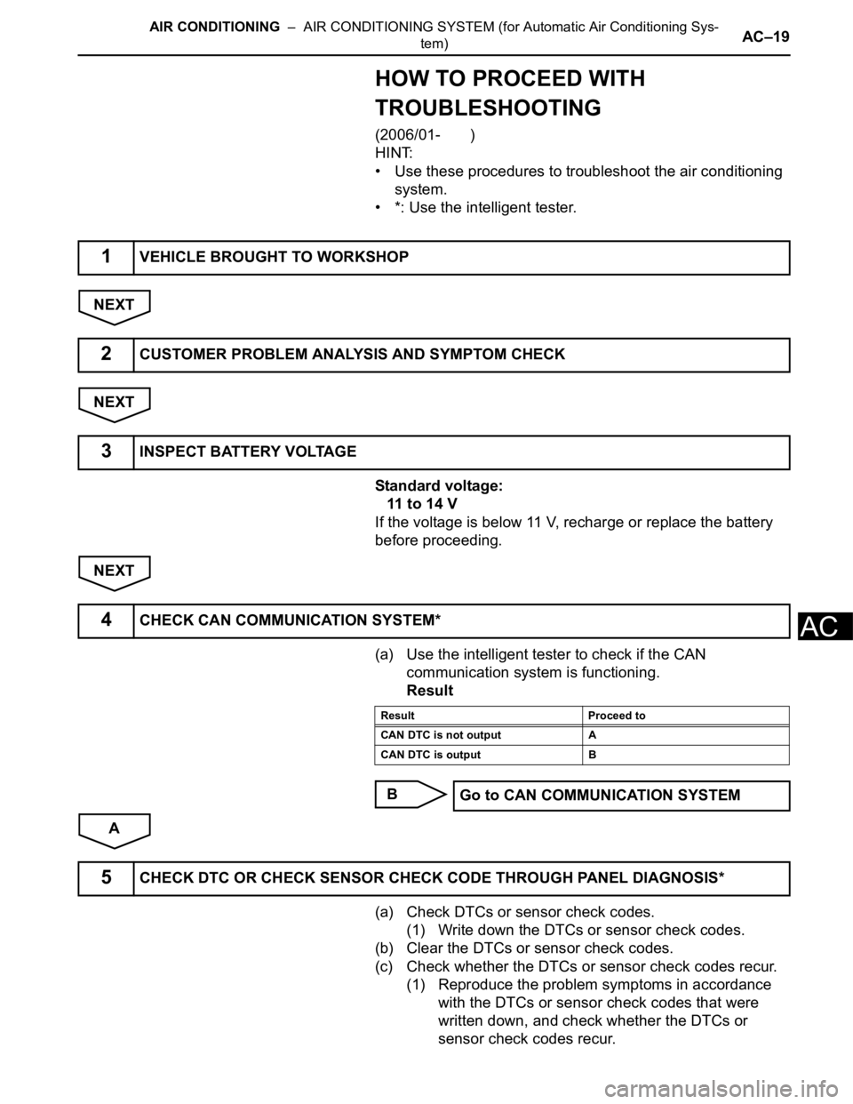
HOW TO PROCEED WITH
TROUBLESHOOTING
(2006/01- )
HINT:
• Use these procedures to troubleshoot the air conditioning
system.
• *: Use the intelligent tester.
NEXT
NEXT
Standard voltage:
11 to 14 V
If the voltage is below 11 V, recharge or replace the battery
before proceeding.
NEXT
(a) Use the intelligent tester to check if the CAN
communication system is functioning.
Result
B
A
(a) Check DTCs or sensor check codes.
(1) Write down the DTCs or sensor check codes.
(b) Clear the DTCs or sensor check codes.
(c) Check whether the DTCs or sensor check codes recur.
(1) Reproduce the problem symptoms in accordance
with the DTCs or sensor check codes that were
written down, and check whether the DTCs or
sensor check codes recur.
1VEHICLE BROUGHT TO WORKSHOP
2CUSTOMER PROBLEM ANALYSIS AND SYMPTOM CHECK
3INSPECT BATTERY VOLTAGE
4CHECK CAN COMMUNICATION SYSTEM*
Result Proceed to
CAN DTC is not output A
CAN DTC is output B
Go to CAN COMMUNICATION SYSTEM
5CHECK DTC OR CHECK SENSOR CHECK CODE THROUGH PANEL DIAGNOSIS*
Page 1648 of 2000
AC–20AIR CONDITIONING – AIR CONDITIONING SYSTEM (for Automatic Air Conditioning Sys-
tem)
AC
HINT:
Refer to the DTC chart when any DTCs or sensor
check codes are output.
Result
B
A
Result
B
A
(a) DATA LIST / ACTIVE TEST (see page AC-37)
(b) Panel diagnosis (indicator check) (see page AC-31)
(c) Panel diagnosis (sensor check) (see page AC-31)
(d) Panel diagnosis (actuator check) (see page AC-31)
(e) Terminals of ECU (see page AC-27)
NEXT
NEXT
NEXT
Result Proceed to
DTC or sensor check code is not
outputA
DTC or sensor check code is output B
Go to step 8
6REFER TO PROBLEM SYMPTOMS TABLE
Result Proceed to
Fault is not listed in problem
symptoms tableA
Fault is listed in problem symptoms
tableB
Go to step 8
7OVERALL ANALYSIS AND TROUBLESHOOTING*
8ADJUST, REPAIR OR REPLACE
9CONFIRMATION TEST
END
Page 1650 of 2000

AC–22AIR CONDITIONING – AIR CONDITIONING SYSTEM (for Automatic Air Conditioning Sys-
tem)
AC
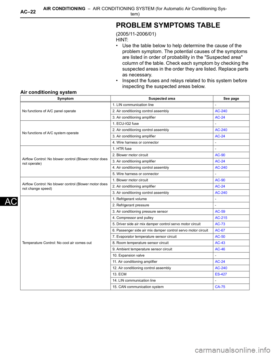
PROBLEM SYMPTOMS TABLE
(2005/11-2006/01)
HINT:
• Use the table below to help determine the cause of the
problem symptom. The potential causes of the symptoms
are listed in order of probability in the "Suspected area"
column of the table. Check each symptom by checking the
suspected areas in the order they are listed. Replace parts
as necessary.
• Inspect the fuses and relays related to this system before
inspecting the suspected areas below.
Air conditioning system
Symptom Suspected area See page
No functions of A/C panel operate1. LIN communication line -
2. Air conditioning control assemblyAC-240
3. Air conditioning amplifierAC-24
No functions of A/C system operate1. ECU-IG2 fuse -
2. Air conditioning control assemblyAC-240
3. Air conditioning amplifierAC-24
4. Wire harness or connector -
Airflow Control: No blower control (Blower motor does
not operate)1. HTR fuse -
2. Blower motor circuitAC-90
3. Air conditioning amplifierAC-24
4. Air conditioning control assemblyAC-240
5. Wire harness or connector -
Airflow Control: No blower control (Blower motor does
not change speed)1. Blower motor circuitAC-90
2. Air conditioning amplifierAC-24
3. Air conditioning control assemblyAC-240
Temperature Control: No cool air comes out1. Refrigerant volume -
2. Refrigerant pressure -
3. Air conditioning pressure sensorAC-59
4. Compressor and pulleyAC-215
5. Driver side air mix damper control servo motor circuitAC-73
6. Passenger side air mix damper control servo motor circuitAC-67
7. Evaporator temperature sensor circuitAC-50
8. Room temperature sensor circuitAC-43
9. Ambient temperature sensor circuitAC-46
10. Expansion valve -
11. Air conditioning amplifierAC-24
12. Air conditioning control assemblyAC-240
13. ECMES-427
14. LIN communication line -
15. CAN communication systemCA-75
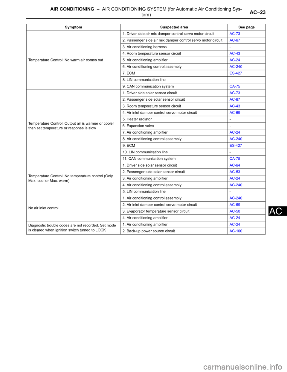
Page 1651 of 2000

AIR CONDITIONING – AIR CONDITIONING SYSTEM (for Automatic Air Conditioning Sys-
tem)AC–23
AC
Temperature Control: No warm air comes out1. Driver side air mix damper control servo motor circuitAC-73
2. Passenger side air mix damper control servo motor circuitAC-67
3. Air conditioning harness -
4. Room temperature sensor circuitAC-43
5. Air conditioning amplifierAC-24
6. Air conditioning control assemblyAC-240
7. ECMES-427
8. LIN communication line -
9. CAN communication systemCA-75
Temperature Control: Output air is warmer or cooler
than set temperature or response is slow1. Driver side solar sensor circuitAC-73
2. Passenger side solar sensor circuitAC-67
3. Room temperature sensor circuitAC-43
4. Air inlet damper control servo motor circuitAC-69
5. Heater radiator -
6. Expansion valve -
7. Air conditioning amplifierAC-24
8. Air conditioning control assemblyAC-240
9. ECMES-427
10. LIN communication line -
11. CAN communication systemCA-75
Temperature Control: No temperature control (Only
Max. cool or Max. warm)1. Driver side solar sensor circuitAC-64
2. Passenger side solar sensor circuitAC-53
3. Air conditioning amplifierAC-24
4. Air conditioning control assemblyAC-240
5. LIN communication line -
No air inlet control1. Air conditioning control assemblyAC-240
2. Air inlet damper control servo motor circuitAC-69
3. Evaporator temperature sensor circuitAC-50
4. Air conditioning amplifierAC-24
Diagnostic trouble codes are not recorded. Set mode
is cleared when ignition switch turned to LOCK1. Air conditioning amplifierAC-24
2. Back-up power source circuitAC-100 Symptom Suspected area See page