Page 901 of 2000
2AZ-FE STARTING – STARTERST–9
ST
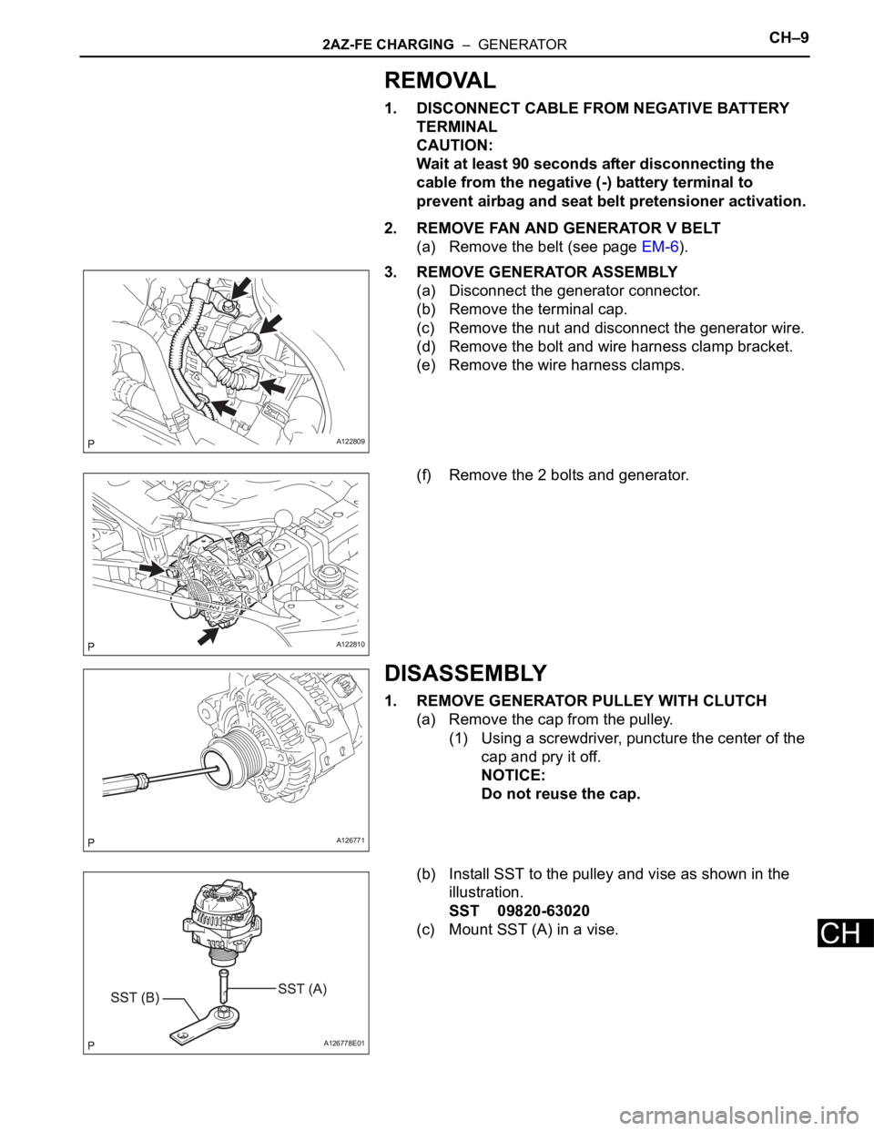
INSPECTION
1. INSPECT STARTER ASSEMBLY
NOTICE:
These tests must be performed within 3 to 5 seconds
to avoid burning out the coil.
(a) Perform the pull-in test.
(1) Disconnect the lead wire from terminal C.
(2) Connect the battery to the magnetic switch as
shown in the illustration. Check that the clutch
pinion gear extends.
If the clutch pinion gear does not move, replace
the magnetic switch.
(b) Perform the hold-in test.
(1) Maintain the battery connections of the pull-in
test above, but disconnect the negative (-) lead
from terminal C. Check that the pinion gear
remains extended.
If the clutch pinion gear returns inward, replace
the magnetic switch.
(c) Check the clutch pinion gear return.
(1) Disconnect the negative (-) lead from the
switch body. Check that the clutch pinion gear
returns.
If the clutch pinion gear does not return,
replace the magnetic switch.
(d) Perform the no-load performance test.
(1) Connect the lead wire to terminal C. Make sure
that the lead is not grounded.
(2) Clamp the starter in a vise.
(3) Connect the battery and an ammeter to the
starter as shown in the illustration.
(4) Check that the starter rotates smoothly and
steadily while the pinion gear is moving out.
Then measure the current.
Standard current:
90 A or less at 11.5 V
If result is not as specified, replace the starter
assembly.
A060459E06
A081044E01
A081045E01
A060462E01
Page 903 of 2000

2AZ-FE STARTING – STARTERST–11
ST
(d) Using a vernier caliper, measure the commutator's
length.
Standard length:
3.1 to 3.8 mm (0.122 to 0.150 in.)
If the length is greater than the maximum, replace
the starter armature assembly.
4. INSPECT STARTER COMMUTATOR END FRAME
ASSEMBLY
(a) Using a vernier caliper, measure the brush length.
Standard length:
4.0 to 9.0 mm (0.158 to 0.359 in.)
If the length is less than the minimum, replace the
end frame assembly.
(b) Check the brush insulation.
(1) Measure the resistance between the positive
(+) and negative (-) brush.
Standard resistance:
10 k
or higher
If the result is not as specified, repair or replace
the end frame assembly.
5. INSPECT STARTER CLUTCH
(a) Check the starter clutch.
(1) Rotate the clutch pinion gear counterclockwise
and check that it turns freely. Try to rotate the
clutch pinion gear clockwise and check that it
locks.
If necessary, replace the starter drive housing
assembly.
A058584E01
A076677E01
A079766E03
A081655E01
Page 912 of 2000
2GR-FE STARTING – STARTERST–9
ST
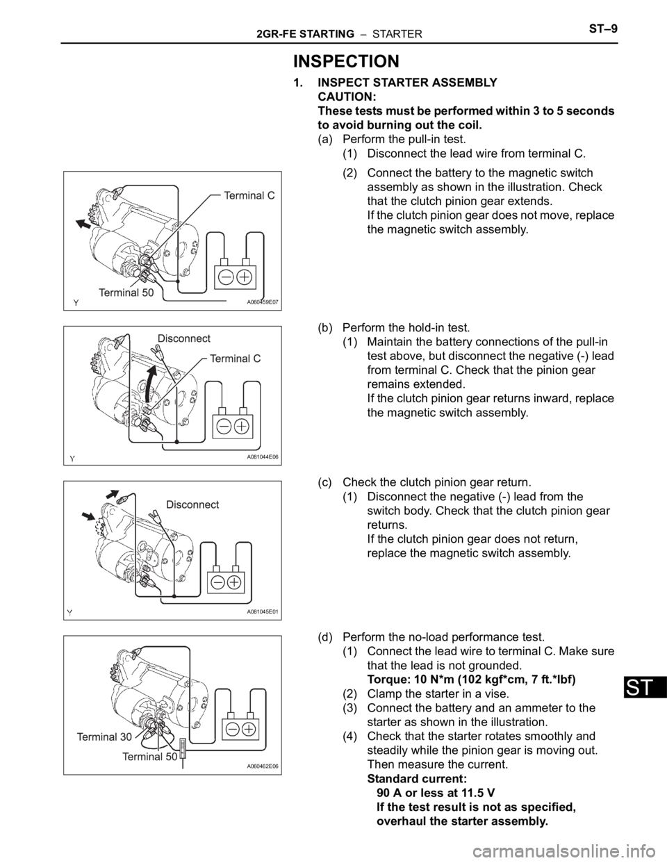
INSPECTION
1. INSPECT STARTER ASSEMBLY
CAUTION:
These tests must be performed within 3 to 5 seconds
to avoid burning out the coil.
(a) Perform the pull-in test.
(1) Disconnect the lead wire from terminal C.
(2) Connect the battery to the magnetic switch
assembly as shown in the illustration. Check
that the clutch pinion gear extends.
If the clutch pinion gear does not move, replace
the magnetic switch assembly.
(b) Perform the hold-in test.
(1) Maintain the battery connections of the pull-in
test above, but disconnect the negative (-) lead
from terminal C. Check that the pinion gear
remains extended.
If the clutch pinion gear returns inward, replace
the magnetic switch assembly.
(c) Check the clutch pinion gear return.
(1) Disconnect the negative (-) lead from the
switch body. Check that the clutch pinion gear
returns.
If the clutch pinion gear does not return,
replace the magnetic switch assembly.
(d) Perform the no-load performance test.
(1) Connect the lead wire to terminal C. Make sure
that the lead is not grounded.
Torque: 10 N*m (102 kgf*cm, 7 ft.*lbf)
(2) Clamp the starter in a vise.
(3) Connect the battery and an ammeter to the
starter as shown in the illustration.
(4) Check that the starter rotates smoothly and
steadily while the pinion gear is moving out.
Then measure the current.
Standard current:
90 A or less at 11.5 V
If the test result is not as specified,
overhaul the starter assembly.
A060459E07
A081044E06
A081045E01
A060462E06
Page 914 of 2000
2GR-FE STARTING – STARTERST–11
ST
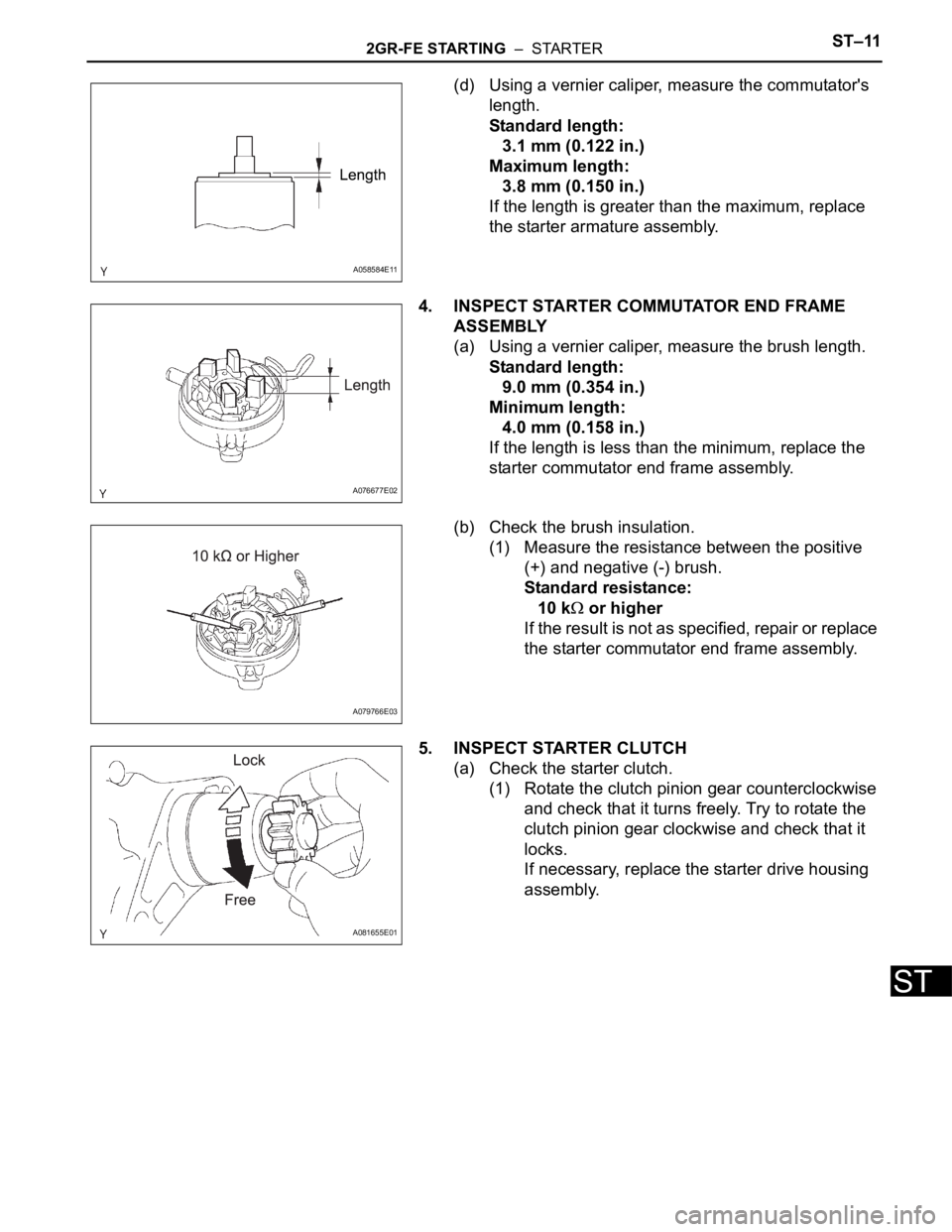
(d) Using a vernier caliper, measure the commutator's
length.
Standard length:
3.1 mm (0.122 in.)
Maximum length:
3.8 mm (0.150 in.)
If the length is greater than the maximum, replace
the starter armature assembly.
4. INSPECT STARTER COMMUTATOR END FRAME
ASSEMBLY
(a) Using a vernier caliper, measure the brush length.
Standard length:
9.0 mm (0.354 in.)
Minimum length:
4.0 mm (0.158 in.)
If the length is less than the minimum, replace the
starter commutator end frame assembly.
(b) Check the brush insulation.
(1) Measure the resistance between the positive
(+) and negative (-) brush.
Standard resistance:
10 k
or higher
If the result is not as specified, repair or replace
the starter commutator end frame assembly.
5. INSPECT STARTER CLUTCH
(a) Check the starter clutch.
(1) Rotate the clutch pinion gear counterclockwise
and check that it turns freely. Try to rotate the
clutch pinion gear clockwise and check that it
locks.
If necessary, replace the starter drive housing
assembly.
A058584E11
A076677E02
A079766E03
A081655E01
Page 920 of 2000
2AZ-FE CHARGING – GENERATORCH–9
CH
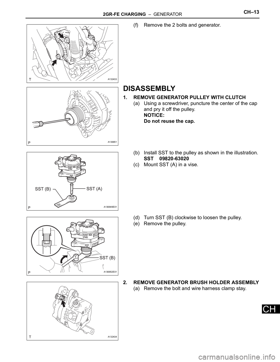
REMOVAL
1. DISCONNECT CABLE FROM NEGATIVE BATTERY
TERMINAL
CAUTION:
Wait at least 90 seconds after disconnecting the
cable from the negative (-) battery terminal to
prevent airbag and seat belt pretensioner activation.
2. REMOVE FAN AND GENERATOR V BELT
(a) Remove the belt (see page EM-6).
3. REMOVE GENERATOR ASSEMBLY
(a) Disconnect the generator connector.
(b) Remove the terminal cap.
(c) Remove the nut and disconnect the generator wire.
(d) Remove the bolt and wire harness clamp bracket.
(e) Remove the wire harness clamps.
(f) Remove the 2 bolts and generator.
DISASSEMBLY
1. REMOVE GENERATOR PULLEY WITH CLUTCH
(a) Remove the cap from the pulley.
(1) Using a screwdriver, puncture the center of the
cap and pry it off.
NOTICE:
Do not reuse the cap.
(b) Install SST to the pulley and vise as shown in the
illustration.
SST 09820-63020
(c) Mount SST (A) in a vise.
A122809
A122810
A126771
A126778E01
Page 923 of 2000
CH–122AZ-FE CHARGING – GENERATOR
CH
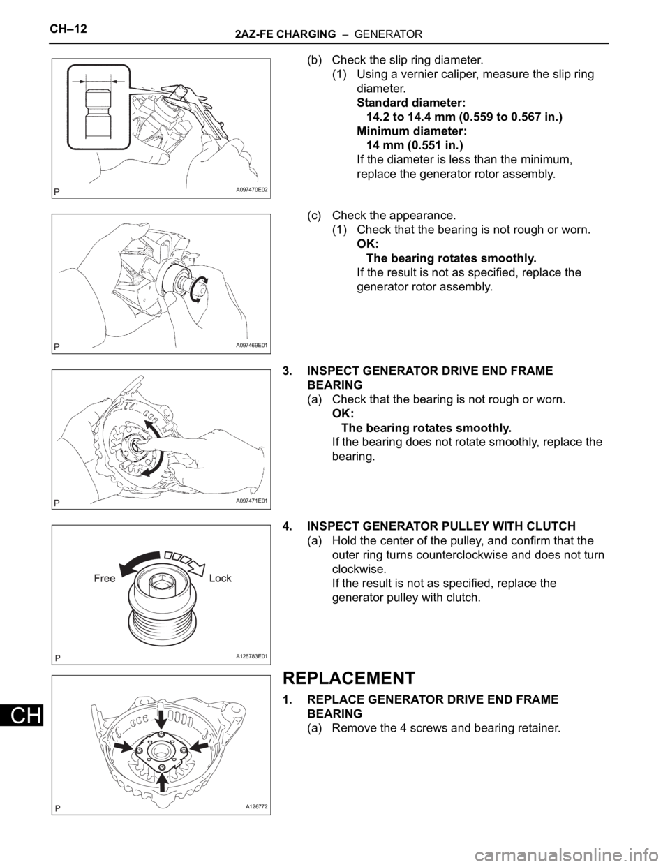
(b) Check the slip ring diameter.
(1) Using a vernier caliper, measure the slip ring
diameter.
Standard diameter:
14.2 to 14.4 mm (0.559 to 0.567 in.)
Minimum diameter:
14 mm (0.551 in.)
If the diameter is less than the minimum,
replace the generator rotor assembly.
(c) Check the appearance.
(1) Check that the bearing is not rough or worn.
OK:
The bearing rotates smoothly.
If the result is not as specified, replace the
generator rotor assembly.
3. INSPECT GENERATOR DRIVE END FRAME
BEARING
(a) Check that the bearing is not rough or worn.
OK:
The bearing rotates smoothly.
If the bearing does not rotate smoothly, replace the
bearing.
4. INSPECT GENERATOR PULLEY WITH CLUTCH
(a) Hold the center of the pulley, and confirm that the
outer ring turns counterclockwise and does not turn
clockwise.
If the result is not as specified, replace the
generator pulley with clutch.
REPLACEMENT
1. REPLACE GENERATOR DRIVE END FRAME
BEARING
(a) Remove the 4 screws and bearing retainer.
A097470E02
A097469E01
A097471E01
A126783E01
A126772
Page 926 of 2000
2AZ-FE CHARGING – GENERATORCH–15
CH
(d) Install the terminal insulator onto the generator
rectifier end frame.
(e) Install the generator rear end cover with the 3 nuts.
Torque: 4.6 N*m (47 kgf*cm, 41 in.*lbf)
3. INSTALL GENERATOR PULLEY WITH CLUTCH
(a) Install the pulley by hand.
(b) Install SST to the pulley and vise as shown in the
illustration.
SST 09820-63020
(c) Turn SST (B) counterclockwise to tighten the pulley.
Torque: 111 N*m (1125 kgf*cm, 81 ft.*lbf)
(d) Install a new cap to the pulley.
(e) Check that the generator pulley rotates smoothly.
INSTALLATION
1. INSTALL GENERATOR ASSEMBLY
(a) Confirm that the wire harness of the crankshaft
position sensor is secured to the wire harness
clamp bracket through the back of the rib of the
timing chain cover.
A097461E01
A098216E01
A126778E01
A126782E01
A097394E02
Page 932 of 2000
2GR-FE CHARGING – GENERATORCH–13
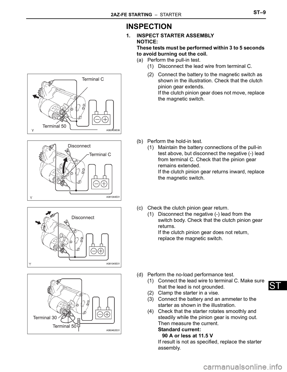
CH
(f) Remove the 2 bolts and generator.
DISASSEMBLY
1. REMOVE GENERATOR PULLEY WITH CLUTCH
(a) Using a screwdriver, puncture the center of the cap
and pry it off the pulley.
NOTICE:
Do not reuse the cap.
(b) Install SST to the pulley as shown in the illustration.
SST 09820-63020
(c) Mount SST (A) in a vise.
(d) Turn SST (B) clockwise to loosen the pulley.
(e) Remove the pulley.
2. REMOVE GENERATOR BRUSH HOLDER ASSEMBLY
(a) Remove the bolt and wire harness clamp stay.
A132433
A136851
A136849E01
A136852E01
A132434