Page 962 of 2000
AX–28U140F AUTOMATIC TRANSAXLE – AUTOMATIC TRANSAXLE SYSTEM
AX
Poor acceleration (all positions)1. Torque converter clutchAX-153
2. U/D planetary gearAX-155
Poor acceleration (O/D)1. C3 U/D clutchAX-155
2. U/D planetary gearAX-155
Large shift shock or engine stalls when starting off or
stoppingTorque converter clutchAX-153
No kick-down Valve body assemblyAX-118 Symptom Suspected area See page
Page 978 of 2000
AX–150U140F AUTOMATIC TRANSAXLE – AUTOMATIC TRANSAXLE ASSEMBLY
AX
INSTALLATION
1. INSPECT TORQUE CONVERTER CLUTCH
ASSEMBLY
(a) Inspect the torque converter (see page AX-153).
2. INSTALL TORQUE CONVERTER CLUTCH
ASSEMBLY
(a) Install the torque converter clutch to the automatic
transaxle.
(b) Using a vernier caliper, measure dimension A
between the transaxle and the end surface of the
drive plate.
(c) Using a vernier caliper and straightedge, measure
the dimension B shown in the illustration and check
that B is greater than A.
Standard dimension:
A + 1.0 mm (0.039 in.) or more
3. INSTALL NO. 1 TRANSMISSION CONTROL CABLE
BRACKET
(a) Install the cable bracket with the 2 bolts.
Torque: 12 N*m (122 kgf*cm, 9 ft.*lbf)
4. INSTALL TRANSMISSION OIL FILLER TUBE SUB-
ASSEMBLY
(a) Install the filler tube with the bolt.
(b) Install the filler tube with the bolt.
Torque: 5.5 N*m (56 kgf*cm, 49 in.*lbf)
(c) Install the ATF dipstick.
C083051E01
C065911E01
C127845
C127846
Page 979 of 2000
U140F AUTOMATIC TRANSAXLE – AUTOMATIC TRANSAXLE ASSEMBLYAX–151
AX
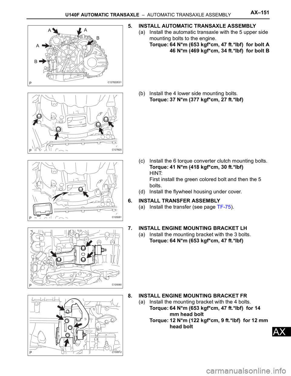
5. INSTALL AUTOMATIC TRANSAXLE ASSEMBLY
(a) Install the automatic transaxle with the 5 upper side
mounting bolts to the engine.
Torque: 64 N*m (653 kgf*cm, 47 ft.*lbf) for bolt A
46 N*m (469 kgf*cm, 34 ft.*lbf) for bolt B
(b) Install the 4 lower side mounting bolts.
Torque: 37 N*m (377 kgf*cm, 27 ft.*lbf)
(c) Install the 6 torque converter clutch mounting bolts.
Torque: 41 N*m (418 kgf*cm, 30 ft.*lbf)
HINT:
First install the green colored bolt and then the 5
bolts.
(d) Install the flywheel housing under cover.
6. INSTALL TRANSFER ASSEMBLY
(a) Install the transfer (see page TF-75).
7. INSTALL ENGINE MOUNTING BRACKET LH
(a) Install the mounting bracket with the 3 bolts.
Torque: 64 N*m (653 kgf*cm, 47 ft.*lbf)
8. INSTALL ENGINE MOUNTING BRACKET FR
(a) Install the mounting bracket with the 4 bolts.
Torque: 64 N*m (653 kgf*cm, 47 ft.*lbf) for 14
mm head bolt
Torque: 12 N*m (122 kgf*cm, 9 ft.*lbf) for 12 mm
head bolt
C127822E01
C127820
C129381
C129380
C130912
Page 983 of 2000
U140F AUTOMATIC TRANSAXLE – AUTOMATIC TRANSAXLE UNITAX–189
AX
5. INSTALL UNDERDRIVE CLUTCH DRUM OIL SEAL
RING
(a) Install 2 new oil seal rings to the transaxle.
6. INSTALL UNDERDRIVE BRAKE PISTON
(a) Wind a vinyl tape around SST at the place 4.0 mm
(0.157 in.) above from the bottom end until the
thickness of the wound tape is about 5.0 mm (0.197
in.)
SST 09950-60010 (09951-00320)
NOTICE:
Clean SST to remove deposited oil before
winding a vinyl tape.
(b) Using SST and a press, press in the needle-roller
bearing to the transaxle until the wound vinyl tape
contacts the transaxle case.
SST 09950-60010 (09951-00320), 09950-70010
(09951-07100)
(c) Coat 2 new O-rings with ATF, and install them to the
underdrive brake piston.
(d) Install the underdrive brake piston to the transaxle.
D003914E04
D003809E03
D003810E01
D003794E02
D003609E01
Page 988 of 2000
AX–194U140F AUTOMATIC TRANSAXLE – AUTOMATIC TRANSAXLE UNIT
AX
15. INSTALL REAR PLANETARY GEAR ASSEMBLY
(a) Coat the bearing race with ATF, and install it to the
rear planetary gear assembly.
Standard bearing race diameter
(b) Install the No. 2 thrust washer.
(c) Install the rear planetary gear to the rear planetary
ring gear.
(d) Using a screwdriver, install the snap ring.
16. INSTALL 1ST AND REVERSE BRAKE CLUTCH DISC
(a) Install the 5 plates and 5 discs.
Install in order:
P - D - P - D - P - D - P - D - P - D
HINT:
P = Plate
D = Disc
D003593E01
Item Inside Outside
Race 38.6 mm (1.520 in.) 58.0 mm (2.83 in.)
D003910E01
D008062E01
D003616E02
C129389E01
Page 989 of 2000
U140F AUTOMATIC TRANSAXLE – AUTOMATIC TRANSAXLE UNITAX–195
AX
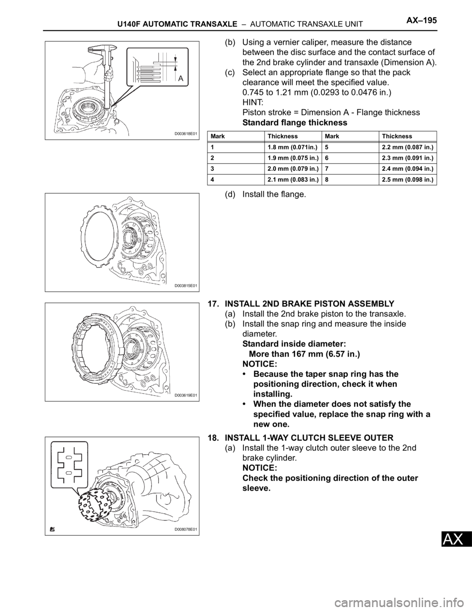
(b) Using a vernier caliper, measure the distance
between the disc surface and the contact surface of
the 2nd brake cylinder and transaxle (Dimension A).
(c) Select an appropriate flange so that the pack
clearance will meet the specified value.
0.745 to 1.21 mm (0.0293 to 0.0476 in.)
HINT:
Piston stroke = Dimension A - Flange thickness
Standard flange thickness
(d) Install the flange.
17. INSTALL 2ND BRAKE PISTON ASSEMBLY
(a) Install the 2nd brake piston to the transaxle.
(b) Install the snap ring and measure the inside
diameter.
Standard inside diameter:
More than 167 mm (6.57 in.)
NOTICE:
• Because the taper snap ring has the
positioning direction, check it when
installing.
• When the diameter does not satisfy the
specified value, replace the snap ring with a
new one.
18. INSTALL 1-WAY CLUTCH SLEEVE OUTER
(a) Install the 1-way clutch outer sleeve to the 2nd
brake cylinder.
NOTICE:
Check the positioning direction of the outer
sleeve.
D003618E01Mark Thickness Mark Thickness
1 1.8 mm (0.071in.) 5 2.2 mm (0.087 in.)
2 1.9 mm (0.075 in.) 6 2.3 mm (0.091 in.)
3 2.0 mm (0.079 in.) 7 2.4 mm (0.094 in.)
4 2.1 mm (0.083 in.) 8 2.5 mm (0.098 in.)
D003815E01
D003619E01
D008078E01
Page 990 of 2000
AX–196U140F AUTOMATIC TRANSAXLE – AUTOMATIC TRANSAXLE UNIT
AX
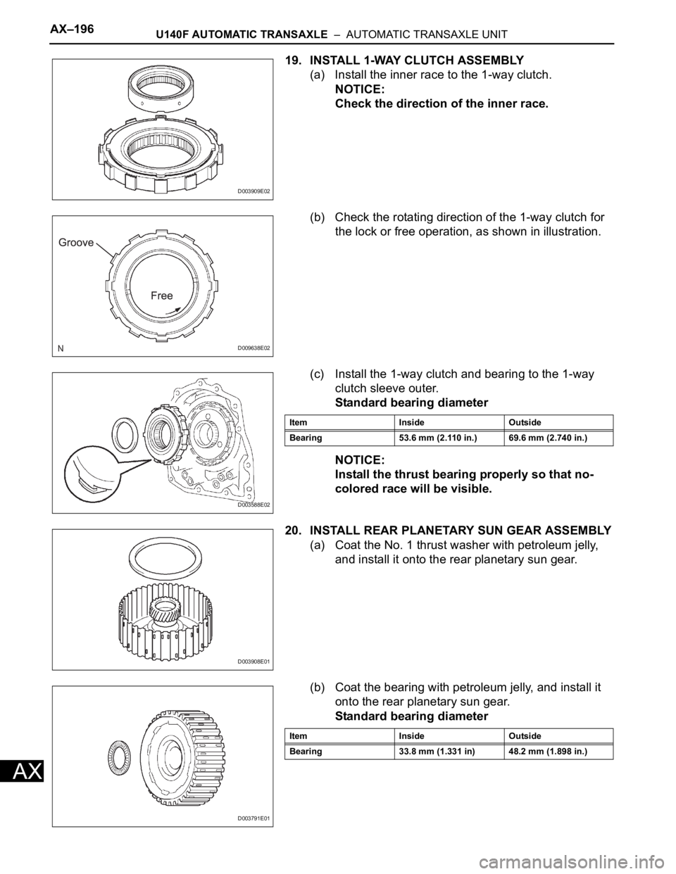
19. INSTALL 1-WAY CLUTCH ASSEMBLY
(a) Install the inner race to the 1-way clutch.
NOTICE:
Check the direction of the inner race.
(b) Check the rotating direction of the 1-way clutch for
the lock or free operation, as shown in illustration.
(c) Install the 1-way clutch and bearing to the 1-way
clutch sleeve outer.
Standard bearing diameter
NOTICE:
Install the thrust bearing properly so that no-
colored race will be visible.
20. INSTALL REAR PLANETARY SUN GEAR ASSEMBLY
(a) Coat the No. 1 thrust washer with petroleum jelly,
and install it onto the rear planetary sun gear.
(b) Coat the bearing with petroleum jelly, and install it
onto the rear planetary sun gear.
Standard bearing diameter
D003909E02
D009638E02
D003588E02
Item Inside Outside
Bearing 53.6 mm (2.110 in.) 69.6 mm (2.740 in.)
D003908E01
D003791E01
Item Inside Outside
Bearing 33.8 mm (1.331 in) 48.2 mm (1.898 in.)
Page 991 of 2000
U140F AUTOMATIC TRANSAXLE – AUTOMATIC TRANSAXLE UNITAX–197
AX
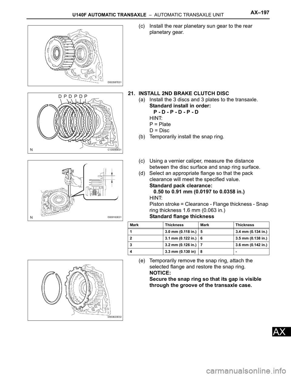
(c) Install the rear planetary sun gear to the rear
planetary gear.
21. INSTALL 2ND BRAKE CLUTCH DISC
(a) Install the 3 discs and 3 plates to the transaxle.
Standard install in order:
P - D - P - D - P - D
HINT:
P = Plate
D = Disc
(b) Temporarily install the snap ring.
(c) Using a vernier caliper, measure the distance
between the disc surface and snap ring surface.
(d) Select an appropriate flange so that the pack
clearance will meet the specified value.
Standard pack clearance:
0.50 to 0.91 mm (0.0197 to 0.0358 in.)
HINT:
Piston stroke = Clearance - Flange thickness - Snap
ring thickness 1.6 mm (0.063 in.)
Standard flange thickness
(e) Temporarily remove the snap ring, attach the
selected flange and restore the snap ring.
NOTICE:
Secure the snap ring so that its gap is visible
through the groove of the transaxle case.
D003587E01
C129390E01
D009163E01
Mark Thickness Mark Thickness
1 3.0 mm (0.118 in.) 5 3.4 mm (0.134 in.)
2 3.1 mm (0.122 in.) 6 3.5 mm (0.138 in.)
3 3.2 mm (0.126 in.) 7 3.6 mm (0.142 in.)
4 3.3 mm (0.130 in) 8 -
D003623E02