Page 414 of 2000
BRAKE CONTROL – VEHICLE STABILITY CONTROL SYSTEMBC–5
BC
C136077E01
Page 415 of 2000

BRAKE – BRAKE SYSTEMBR–3
BR
PROBLEM SYMPTOMS TABLE
(2005/11-2006/01)
HINT:
Use the table below to help determine the cause of the
problem symptom. The potential causes of the symptoms are
listed in order of probability in the "Suspected area" column of
the table. Check each symptom by checking the suspected
areas in the order they are listed. Replace parts as
necessary.
Brake system
Symptom Suspected area See page
Low pedal or spongy pedal1. Fluid leaks in brake system -
2. Air in brake systemBR-6
3. Front brake piston seals (worn or damaged)BR-40
4. Rear brake piston seals (worn or damaged)BR-55
5. Brake master cylinder (faulty)BR-21
6. Booster push rod (adjustment necessary)BR-24
Brake drag1. Brake pedal free play (minimum)BR-14
2. Parking brake lever travel (adjustment necessary)PB-1
3. Parking brake cable (sticking)PB-8
4. Parking brake shoe clearance (adjustment necessary)PB-17
5. Front brake pad (cracked or distorted)BR-40
6. Rear brake pad (cracked or distorted)BR-55
7. Parking brake lining (cracked or distorted)PB-13
8. Front brake piston (stuck or frozen)BR-40
9. Rear brake piston (stuck or frozen)BR-55
10. Parking brake shoe return tension springPB-13
11. Booster push rod (adjustment necessary)BR-24
12. Vacuum leaks in booster systemBR-29
13. Brake master cylinder (faulty)BR-21
Brake pull1. Front brake piston (stuck or frozen)BR-40
2. Rear brake piston (stuck or frozen)BR-55
3. Front brake pad (oily, cracked or distorted)BR-40
4. Rear brake pad (oily, cracked or distorted)BR-55
5. Parking brake lining (oily, cracked or distorted)PB-13
6. Front brake disc (uneven wear)BR-40
7. Rear brake disc (uneven wear)BR-55
Hard pedal but braking inefficient1. Front brake pad (worn, cracked, distorted, oily or glazed)BR-40
2. Rear brake pad (worn, cracked, distorted, oily or glazed)BR-55
3. Parking brake lining (worn, cracked, distorted, oily or
glazed)PB-13
4. Front brake disc (uneven wear)BR-40
5. Rear brake disc (uneven wear)BR-55
6. Booster push rod (adjustment necessary)BR-24
7. Vacuum leaks in booster systemBR-29
Page 416 of 2000
BR–4BRAKE – BRAKE SYSTEM
BR
Noise from brakes1. Front brake pad (cracked, distorted, dirty or glazed)BR-40
2. Rear brake pad (cracked, distorted, dirty or glazed)BR-55
3. Front disc brake pad support plate (loose)BR-40
4. Rear disc brake pad support plate (loose)BR-55
5. Front disc brake cylinder slide pin (worn)BR-40
6. Rear disc brake cylinder slide pin (worn)BR-55
7. Front brake installation bolt (loose)BR-45
8. Rear brake installation bolt (loose)BR-60
9. Front brake disc (scored)BR-40
10. Rear brake disc (scored)BR-55
11. Parking brake shoe return tension spring (faulty)PB-13
12. Front brake anti-squeal shim (damaged)BR-40
13. Rear brake anti-squeal shim (damaged)BR-55
14. Parking brake shoe hold-down spring (damaged)PB-13 Symptom Suspected area See page
Page 417 of 2000

PARKING BRAKE – PARKING BRAKE LEVERPB–5
PB
REMOVAL
1. DISCONNECT CABLE FROM NEGATIVE BATTERY
TERMINAL
CAUTION:
Wait at least 90 seconds after disconnecting the
cable from the negative (-) battery terminal to
prevent airbag and seat belt pretensioner activation.
2. REMOVE REAR CONSOLE BOX SUB-ASSEMBLY
(a) Remove the rear console box (see page IP-16).
HINT:
Refer to the procedures from the removal of the No.
1 console upper panel garnish up until the removal
of the rear console box sub-assembly.
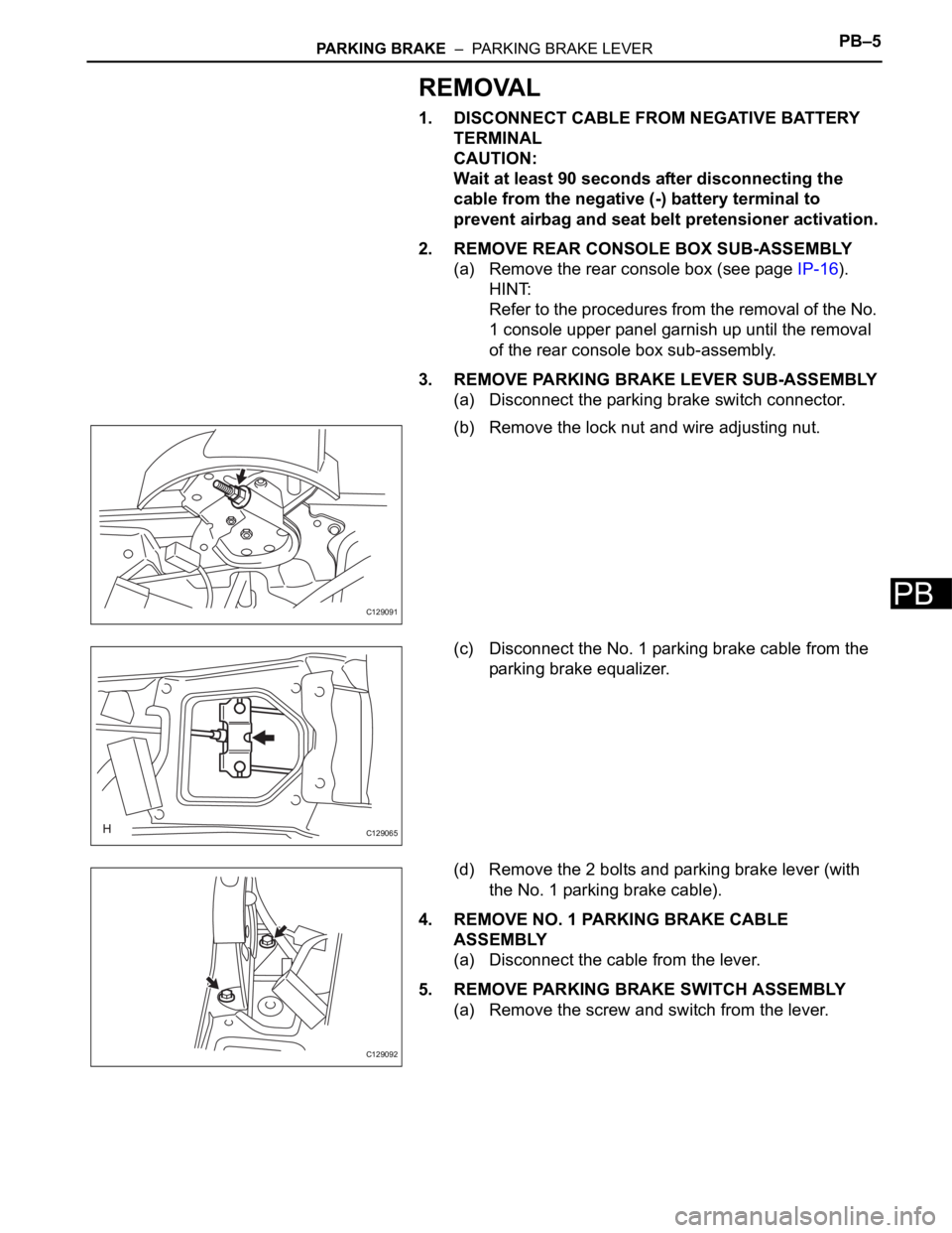
3. REMOVE PARKING BRAKE LEVER SUB-ASSEMBLY
(a) Disconnect the parking brake switch connector.
(b) Remove the lock nut and wire adjusting nut.
(c) Disconnect the No. 1 parking brake cable from the
parking brake equalizer.
(d) Remove the 2 bolts and parking brake lever (with
the No. 1 parking brake cable).
4. REMOVE NO. 1 PARKING BRAKE CABLE
ASSEMBLY
(a) Disconnect the cable from the lever.
5. REMOVE PARKING BRAKE SWITCH ASSEMBLY
(a) Remove the screw and switch from the lever.
C129091
C129065
C129092
Page 418 of 2000

PB–6PARKING BRAKE – PARKING BRAKE LEVER
PB
INSTALLATION
1. INSTALL PARKING BRAKE SWITCH ASSEMBLY
(a) Install the parking brake switch with the screw.
Torque: 0.88 N*m (9.0 kgf*cm, 7.8 in.*lbf)
2. INSTALL NO. 1 PARKING BRAKE CABLE ASSEMBLY
(a) Connect the cable to the lever.
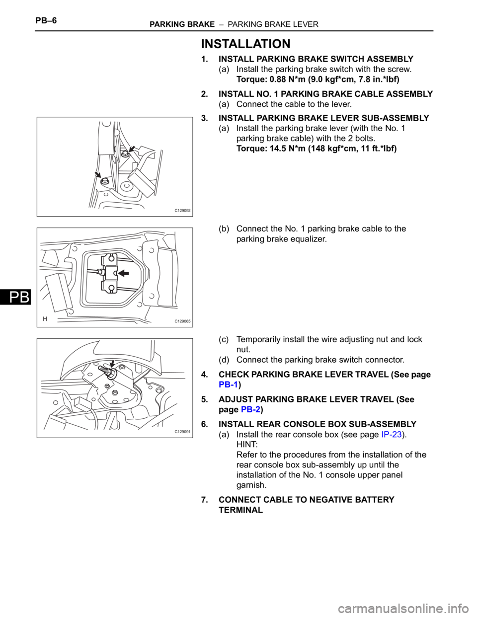
3. INSTALL PARKING BRAKE LEVER SUB-ASSEMBLY
(a) Install the parking brake lever (with the No. 1
parking brake cable) with the 2 bolts.
Torque: 14.5 N*m (148 kgf*cm, 11 ft.*lbf)
(b) Connect the No. 1 parking brake cable to the
parking brake equalizer.
(c) Temporarily install the wire adjusting nut and lock
nut.
(d) Connect the parking brake switch connector.
4. CHECK PARKING BRAKE LEVER TRAVEL (See page
PB-1)
5. ADJUST PARKING BRAKE LEVER TRAVEL (See
page PB-2)
6. INSTALL REAR CONSOLE BOX SUB-ASSEMBLY
(a) Install the rear console box (see page IP-23).
HINT:
Refer to the procedures from the installation of the
rear console box sub-assembly up until the
installation of the No. 1 console upper panel
garnish.
7. CONNECT CABLE TO NEGATIVE BATTERY
TERMINAL
C129092
C129065
C129091
Page 442 of 2000
CC–4CRUISE CONTROL – CRUISE CONTROL SYSTEM
CC
SYSTEM DIAGRAM
Communication table
Sender Receiver Signal Line
ECM Skid control ECU with actuator• VSC operation signal
• Coast brake operation signalCAN
ECM Combination meterCRUISE main indicator light
signalCAN
E129446E01
Page 443 of 2000

CRUISE CONTROL – CRUISE CONTROL SYSTEMCC–5
CC
SYSTEM DESCRIPTION
1. CRUISE CONTROL SYSTEM
This system is controlled by the ECM, and is activated by
the throttle position sensor and motor. The ECM controls
the following functions: ON-OFF, SET / COAST,
RESUME / ACCEL, CANCEL, vehicle speed operation,
motor output control, and overdrive control.
• The ECM compares the driving vehicle speed from
the combination meter with the stored vehicle speed
set through the cruise control switch. The ECM
controls the throttle valve motor of the throttle body to
open the valve when the driving speed is less than the
stored speed.
• The ECM receives signals such as ON-OFF, SET /
COAST, RESUME / ACCEL, and CANCEL from the
cruise control switch.
• The ECM illuminates the combination meter CRUISE
main indicator light when it receives the cruise control
switch ON signal.
• The ECM cancels the cruise control system when the
brake pedal is depressed and the ECM receives the
stop light switch signal.
• The ECM cancels the cruise control system when the
shift lever is moved from D or 3 to a position other
than D or 3, and the ECM receives the PNP switch
signal.
2. LIMIT CONTROL
(a) Low speed limit
The lowest possible limit of the speed setting range
is set at approximately 40 km/h (25 mph). The
cruise control system cannot be set when the
driving vehicle speed is below the low speed limit.
Cruise control operation will be automatically
canceled when the vehicle speed decreases below
the low speed limit 40 km/h (25 mph) while the
cruise control is in operation.
(b) High speed limit
The highest possible limit of the speed setting range
is set at approximately 200 km/h (125 mph). The
cruise control system cannot be set when the
driving vehicle speed is over the high speed limit.
Also, +/RES cannot be used to increase speed
beyond the high speed limit.
Page 444 of 2000

CC–6CRUISE CONTROL – CRUISE CONTROL SYSTEM
CC
3. OPERATION OF CRUISE CONTROL
The cruise control switch operates 7 functions: SET,
COAST, TAP-DOWN, RESUME, ACCELERATION
(ACCEL), TAP-UP, and CANCEL. The SET, TAP-DOWN
and COAST functions, and the RESUME, TAP-UP and
ACCEL functions are operated with the same switch.
The cruise control switch is an automatic return type
switch which turns on only when pressed in each arrow
direction and turns off when released.
(a) SET CONTROL
Vehicle speed is stored and constant speed control
is maintained when pushing the switch to -/SET
while driving with the cruise control switch ON (the
CRUISE main indicator light is illuminated), and the
vehicle speed is within the set speed range
(between the low and high speed limits).
(b) COAST CONTROL
The ECM changes the cruise control demanding
throttle opening angle to 0
and decelerates the
vehicle when -/SET on the cruise control switch is
pressed and held while the cruise control system is
operating. When the cruise control switch is
released from -/SET, the vehicle speed is stored and
constant speed control is maintained.
HINT:
• The throttle valve is not fully closed due to idle
speed control, etc.
•w/ VSC:
The brake is also used to decelerate the vehicle.
(c) TAP-DOWN CONTROL
When tapping down the cruise control switch to -/
SET (for approximately 0.5 seconds) while the
cruise control system is in operation, the stored
vehicle speed decreases each time by
approximately 1.6 km/h (1.0 mph). When the cruise
control switch is released from -/SET and the
difference between the driving and stored vehicle
speed is less than 5 km/h (3 mph), the vehicle
speed is stored and constant speed control is
maintained.
(d) ACCEL CONTROL
The throttle valve motor of the throttle position
sensor and motor is instructed by the ECM to open
the throttle valve when +/RES on the cruise control
switch is pressed and held while the cruise control
system is operating. When the cruise control switch
is released from +/RES, the vehicle speed is stored
and constant speed is maintained.