2006 TOYOTA RAV4 Brake
[x] Cancel search: BrakePage 182 of 2000
MAINTENANCE – UNDER HOODMA–7
MA
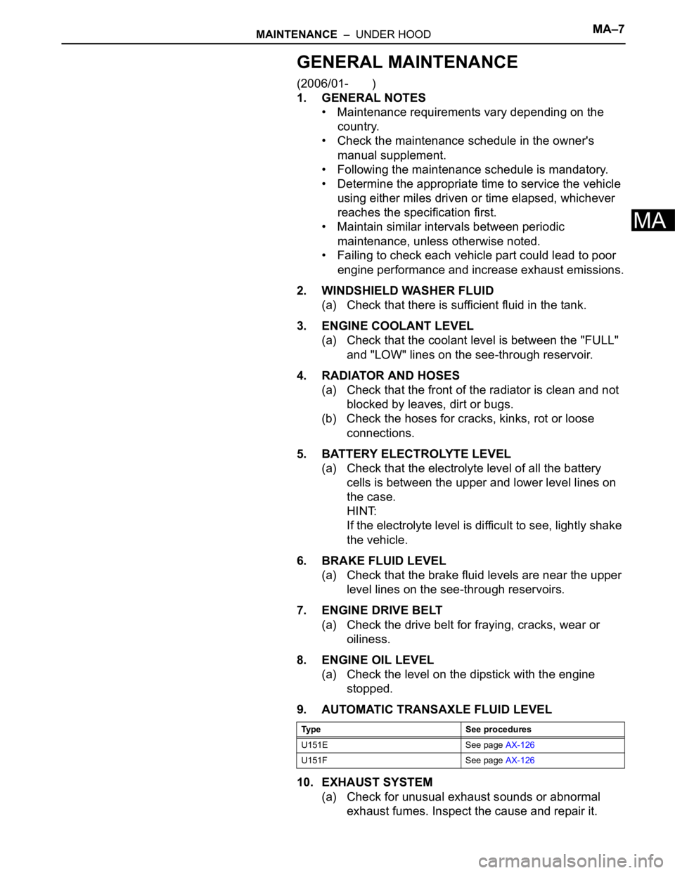
GENERAL MAINTENANCE
(2006/01- )
1. GENERAL NOTES
• Maintenance requirements vary depending on the
country.
• Check the maintenance schedule in the owner's
manual supplement.
• Following the maintenance schedule is mandatory.
• Determine the appropriate time to service the vehicle
using either miles driven or time elapsed, whichever
reaches the specification first.
• Maintain similar intervals between periodic
maintenance, unless otherwise noted.
• Failing to check each vehicle part could lead to poor
engine performance and increase exhaust emissions.
2. WINDSHIELD WASHER FLUID
(a) Check that there is sufficient fluid in the tank.
3. ENGINE COOLANT LEVEL
(a) Check that the coolant level is between the "FULL"
and "LOW" lines on the see-through reservoir.
4. RADIATOR AND HOSES
(a) Check that the front of the radiator is clean and not
blocked by leaves, dirt or bugs.
(b) Check the hoses for cracks, kinks, rot or loose
connections.
5. BATTERY ELECTROLYTE LEVEL
(a) Check that the electrolyte level of all the battery
cells is between the upper and lower level lines on
the case.
HINT:
If the electrolyte level is difficult to see, lightly shake
the vehicle.
6. BRAKE FLUID LEVEL
(a) Check that the brake fluid levels are near the upper
level lines on the see-through reservoirs.
7. ENGINE DRIVE BELT
(a) Check the drive belt for fraying, cracks, wear or
oiliness.
8. ENGINE OIL LEVEL
(a) Check the level on the dipstick with the engine
stopped.
9. AUTOMATIC TRANSAXLE FLUID LEVEL
10. EXHAUST SYSTEM
(a) Check for unusual exhaust sounds or abnormal
exhaust fumes. Inspect the cause and repair it.
Type See procedures
U151E See page AX-126
U151F See page AX-126
Page 386 of 2000
SERVICE SPECIFICATIONS – U151F AUTOMATIC TRANSMISSIONSS–53
SS
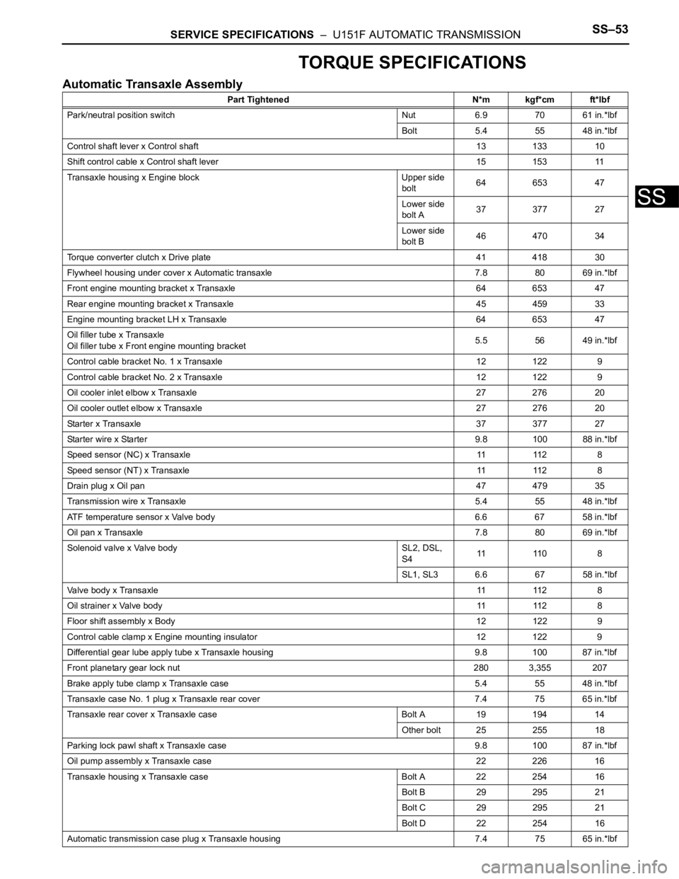
TORQUE SPECIFICATIONS
Automatic Transaxle Assembly
Part Tightened N*m kgf*cm ft*lbf
Park/neutral position switch Nut 6.9 70 61 in.*lbf
Bolt 5.4 55 48 in.*lbf
Control shaft lever x Control shaft 13 133 10
Shift control cable x Control shaft lever 15 153 11
Transaxle housing x Engine block Upper side
bolt64 653 47
Lower side
bolt A37 377 27
Lower side
bolt B46 470 34
Torque converter clutch x Drive plate 41 418 30
Flywheel housing under cover x Automatic transaxle 7.8 80 69 in.*lbf
Front engine mounting bracket x Transaxle 64 653 47
Rear engine mounting bracket x Transaxle 45 459 33
Engine mounting bracket LH x Transaxle 64 653 47
Oil filler tube x Transaxle
Oil filler tube x Front engine mounting bracket5.5 56 49 in.*lbf
Control cable bracket No. 1 x Transaxle 12 122 9
Control cable bracket No. 2 x Transaxle 12 122 9
Oil cooler inlet elbow x Transaxle 27 276 20
Oil cooler outlet elbow x Transaxle 27 276 20
Starter x Transaxle37 377 27
Starter wire x Starter9.8 100 88 in.*lbf
Speed sensor (NC) x Transaxle11 11 2 8
Speed sensor (NT) x Transaxle11 11 2 8
Drain plug x Oil pan47 479 35
Transmission wire x Transaxle5.4 55 48 in.*lbf
ATF temperature sensor x Valve body 6.6 67 58 in.*lbf
Oil pan x Transaxle7.8 80 69 in.*lbf
Solenoid valve x Valve body SL2, DSL,
S411 11 0 8
SL1, SL3 6.6 67 58 in.*lbf
Valve body x Transaxle11 11 2 8
Oil strainer x Valve body11 11 2 8
Floor shift assembly x Body12 122 9
Control cable clamp x Engine mounting insulator 12 122 9
Differential gear lube apply tube x Transaxle housing 9.8 100 87 in.*lbf
Front planetary gear lock nut280 3,355 207
Brake apply tube clamp x Transaxle case 5.4 55 48 in.*lbf
Transaxle case No. 1 plug x Transaxle rear cover 7.4 75 65 in.*lbf
Transaxle rear cover x Transaxle case Bolt A 19 194 14
Other bolt 25 255 18
Parking lock pawl shaft x Transaxle case 9.8 100 87 in.*lbf
Oil pump assembly x Transaxle case 22 226 16
Transaxle housing x Transaxle case Bolt A 22 254 16
Bolt B 29 295 21
Bolt C 29 295 21
Bolt D 22 254 16
Automatic transmission case plug x Transaxle housing 7.4 75 65 in.*lbf
Page 388 of 2000

SERVICE SPECIFICATIONS – U140F AUTOMATIC TRANSAXLESS–59
SS
TORQUE SPECIFICATIONS
Automatic Transaxle Assembly
Automatic Transaxle Unit
Part Tightened N*m kgf*cm ft.*lbf
Park/neutral position switch Nut 6.9 70 61 in.*lbf
Bolt 5.4 55 48 in.*lbf
Control shaft lever x Control shaft 12.7 130 9
Shift control cable x Control shaft lever 15 153 11
Transaxle housing x Engine block A bolt 64 653 47
B bolt 46 470 34
Lower side bolt 37 377 27
Torque converter clutch x Drive plate 41 418 30
Engine mounting bracket FR x Transaxle 64 653 47
Oil filler tube x Transaxle 5.5 56 49 in.*lbf
Control cable bracket No.1 x Transaxle 12 122 9
Oil cooler tube clamp x Control cable bracket 5.4 55 48 in.*lbf
Oil cooler inlet tube x Transaxle 34 347 25
Oil cooler outlet tube x Transaxle 34 347 25
Starter x Transaxle37 377 27
Wire harness x Transaxle 13 133 10
Speed sensor (NC) x Transaxle 11 115 8
Speed sensor (NT) x Transaxle 11 112 8
Air cleaner x No. 1 air cleaner inlet 5.0 51 44 in.*lbf
Drain plug x Oil pan47 479 35
Transmission wire x Transaxle 5.4 55 48 in.*lbf
ATF temperature sensor x Valve body 6.6 67 58 in.*lbf
Oil pan x Transaxle7.6 77 67 in.*lbf
Solenoid valve x Valve body Bolt A 6.6 67 58 in.*lbf
Bolt B 11 110 8
Valve body x Transaxle 10.8 110 8
Oil strainer x Valve body 11 110 8
Floor shift assembly x Body 12 120 9
Control cable x Body5.0 51 44 in.*lbf
Transfer x Transaxle69 704 51
Engine mount bracket RR x Transfer stiffener, plate RH 45 459 34
Part Tightened N*m kgf*cm ft.*lbf
Differential gear lube apply tube x Transaxle housing 9.8 100 7
Front planetary gear lock nut 268 2,732 198
Brake apply tube clamp x Transaxle case 5.4 55 48 in.*lbf
Transaxle case No. 1 plug x Transaxle rear cover 7.4 75 65 in.*lbf
Transaxle rear cover plate x transaxle rear cover sub-assembly 7.5 76 66 in.*lbf
Transaxle rear cover x Transaxle case Bolt A 18.6 190 14
Other bolt 24.5 250 18
Pawl shaft clamp x Transaxle case 9.8 100 7
Oil pump assembly x Transaxle case 22 226 16
Transaxle housing x Transaxle case Bolt A 22.1 225 16.3
Bolt B, C 29.4 300 21.7
Transaxle case No. 1 plug x Transaxle housing 7.4 75 65 in.*lbf
Parking lock pawl bracket x Transaxle case 20 205 15
Page 390 of 2000

SS–64SERVICE SPECIFICATIONS – U241E AUTOMATIC TRANSAXLE
SS
TORQUE SPECIFICATIONS
Automatic Transaxle Assembly
Automatic Transaxle Unit
Part Tightened N*m kgf*cm ft.*lbf
Park/neutral position switch Nut 6.9 70 61 in.*lbf
Bolt 5.4 55 48 in.*lbf
Control shaft lever x Control shaft 12.7 130 9
Shift control cable x Control shaft lever 15 153 11
Transaxle housing x Engine block A bolt 64 653 47
B bolt 46 470 34
Lower side bolt 37 377 27
Torque converter clutch x Drive plate 41 418 30
Engine mounting bracket FR x Transaxle 64 653 47
Oil filler tube x Transaxle 5.5 56 49 in.*lbf
Control cable bracket No.1 x Transaxle 12 122 9
Oil cooler tube clamp x Control cable bracket 5.4 55 48 in.*lbf
Oil cooler inlet tube x Transaxle 34 347 25
Oil cooler outlet tube x Transaxle 34 347 25
Starter x Transaxle37 377 27
Wire harness x Transaxle 13 133 10
Speed sensor (NC) x Transaxle 11 115 8
Speed sensor (NT) x Transaxle 11 112 8
Air cleaner x No. 1 air cleaner inlet 5.0 51 44 in.*lbf
Drain plug x Oil pan47 479 35
Transmission wire x Transaxle 5.4 55 48 in.*lbf
ATF temperature sensor x Valve body 6.6 67 58 in.*lbf
Oil pan x Transaxle7.6 77 67 in.*lbf
Solenoid valve x Valve body Bolt A 6.6 67 58 in.*lbf
B o l t B 11 11 0 8
Valve body x Transaxle 10.8 110 8
Oil strainer x Valve body 11 110 8
Floor shift assembly x Body 12 120 9
Control cable x Body5.0 51 44 in.*lbf
Engine mount bracket RR x Transfer stiffener, plate RH 45 459 34
Part Tightened N*m kgf*cm ft.*lbf
Differential gear lube apply tube x Transaxle housing 9.8 100 7
Front planetary gear lock nut 268 2,732 198
Brake apply tube clamp x Transaxle case 5.4 55 48 in.*lbf
Transaxle case No. 1 plug x Transaxle rear cover 7.4 75 65 in.*lbf
Transaxle rear cover plate x transaxle rear cover sub-assembly 7.5 76 66 in.*lbf
Transaxle rear cover x Transaxle case Bolt A 18.6 190 14
Other bolt 24.5 250 18
Pawl shaft clamp x Transaxle case 9.8 100 7
Oil pump assembly x Transaxle case 22 226 16
Transaxle housing x Transaxle case Bolt A 22.1 225 16.3
Bolt B, C 29.4 300 21.7
Transaxle case No. 1 plug x Transaxle housing 7.4 75 65 in.*lbf
Parking lock pawl bracket x Transaxle case 20 205 15
Detent spring x Transaxle case Bolt A 20 205 15
Bolt B 12 120 9
Page 395 of 2000
SERVICE SPECIFICATIONS – BRAKESS–83
SS
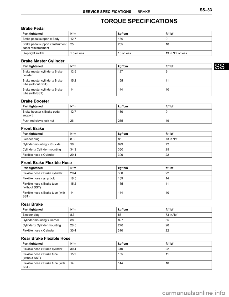
TORQUE SPECIFICATIONS
Brake Pedal
Brake Master Cylinder
Brake Booster
Front Brake
Front Brake Flexible Hose
Rear Brake
Rear Brake Flexible Hose
Part tightened N*m kgf*cm ft.*lbf
Brake pedal support x Body 12.7 130 9
Brake pedal support x Instrument
panel reinforcement25 255 18
Stop light switch 1.5 or less 15 or less 13 in.*lbf or less
Part tightened N*m kgf*cm ft.*lbf
Brake master cylinder x Brake
booster12.5 127 9
Brake master cylinder x Brake
tube (without SST)15.2 155 11
Brake master cylinder x Brake
tube (with SST)14 144 10
Part tightened N*m kgf*cm ft.*lbf
Brake booster x Brake pedal
support12.7 130 9
Push rod clevis lock nut 26 265 19
Part tightened N*m kgf*cm ft.*lbf
Bleeder plug 8.3 85 73 in.*lbf
Cylinder mounting x Knuckle 98 999 72
Cylinder x Cylinder mounting 34.3 350 25
Flexible hose x Cylinder 29.4 300 22
Part tightened N*m kgf*cm ft.*lbf
Flexible hose x Brake cylinder 29.4 300 22
Flexible hose clamp bolt 18.5 189 14
Flexible hose x Brake tube
(without SST)15.2 155 11
Flexible hose x Brake tube (with
SST)14 144 10
Part tightened N*m kgf*cm ft.*lbf
Bleeder plug 8.3 85 73 in.*lbf
Cylinder mounting x Carrier 88 897 65
Cylinder x Cylinder mounting 26.5 270 20
Flexible hose x Cylinder 30.4 310 22
Part tightened N*m kgf*cm ft.*lbf
Flexible hose x Brake cylinder 30.4 310 22
Flexible hose x Brake tube
(without SST)15.2 155 11
Flexible hose x Brake tube (with
SST)14 144 10
Page 403 of 2000
AH–6AXLE – FRONT AXLE HUB
AH
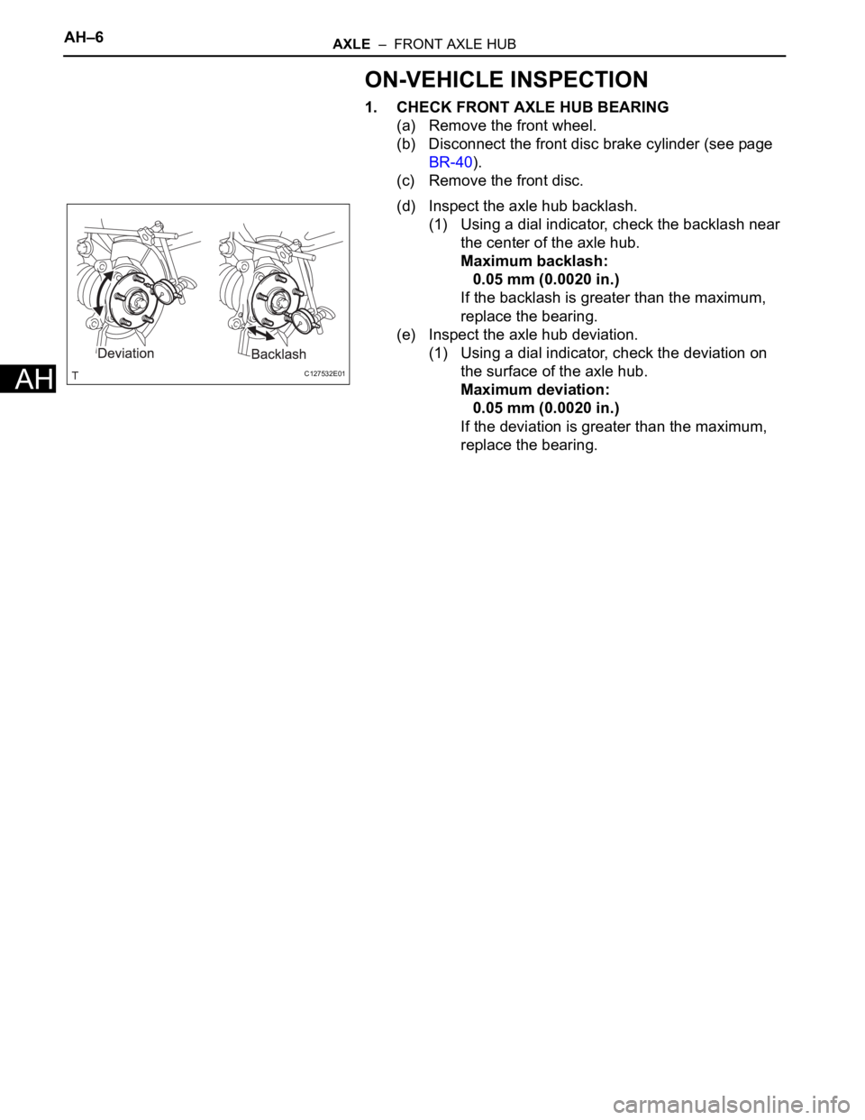
ON-VEHICLE INSPECTION
1. CHECK FRONT AXLE HUB BEARING
(a) Remove the front wheel.
(b) Disconnect the front disc brake cylinder (see page
BR-40).
(c) Remove the front disc.
(d) Inspect the axle hub backlash.
(1) Using a dial indicator, check the backlash near
the center of the axle hub.
Maximum backlash:
0.05 mm (0.0020 in.)
If the backlash is greater than the maximum,
replace the bearing.
(e) Inspect the axle hub deviation.
(1) Using a dial indicator, check the deviation on
the surface of the axle hub.
Maximum deviation:
0.05 mm (0.0020 in.)
If the deviation is greater than the maximum,
replace the bearing.
C127532E01
Page 404 of 2000

AXLE – FRONT AXLE HUBAH–7
AH
REMOVAL
(2005/11-2006/01)
HINT:
• Use the same procedures for the RH side and LH side.
• The procedures listed below are for the LH side.
1. REMOVE FRONT WHEEL
2. DRAIN AUTOMATIC TRANSAXLE FLUID
(a) Drain the automatic transaxle fluid for U140F (see
page AX-147).
(b) Drain the automatic transaxle fluid for U241E (see
page AX-146).
3. DISCONNECT CABLE FROM NEGATIVE BATTERY
TERMINAL
CAUTION:
Wait at least 90 seconds after disconnecting the
cable from the negative (-) battery terminal to
prevent airbag and seat belt pretensioner activation.
4. REMOVE FRONT AXLE HUB NUT
(a) Using SST and a hammer, unstake the staked part
of the nut.
SST 09930-00010
NOTICE:
Loosen the staked part of the nut completely,
otherwise the screw of the drive shaft may be
damaged.
(b) While applying the brakes, remove the lock axle hub
nut.
5. REMOVE FRONT SPEED SENSOR LH (See page BC-
191)
6. REMOVE FRONT DISC BRAKE CYLINDER
ASSEMBLY LH (See page BR-40)
7. REMOVE FRONT DISC (See page BR-42)
8. DISCONNECT TIE ROD END SUB-ASSEMBLY LH
(See page PS-42)
9. DISCONNECT FRONT SUSPENSION NO. 1 LOWER
ARM SUB-ASSEMBLY LH
(a) Remove the bolt and 2 nuts.
(b) Disconnect the lower arm from the ball joint.
C129483E01
C127531
Page 413 of 2000
BC–4BRAKE CONTROL – VEHICLE STABILITY CONTROL SYSTEM
BC
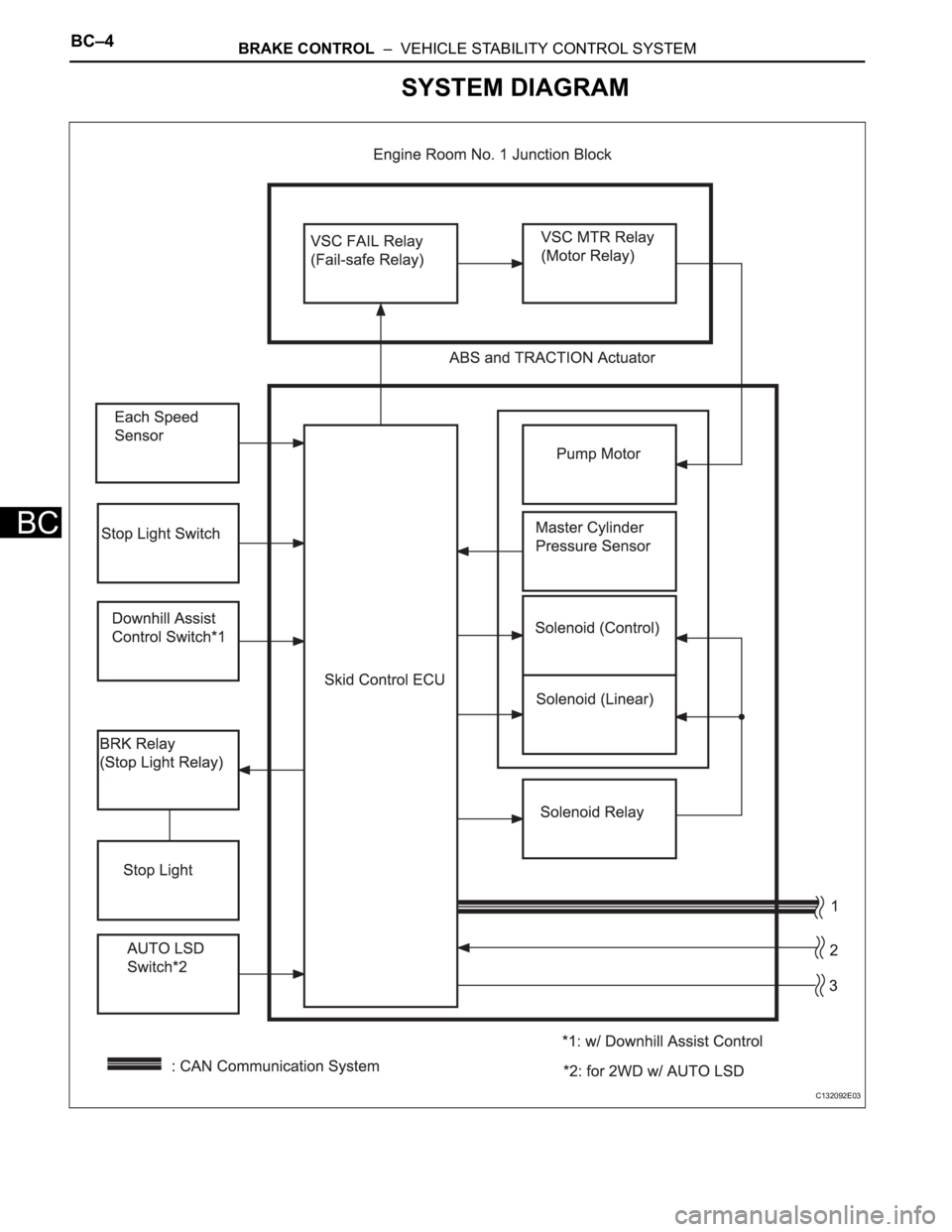
SYSTEM DIAGRAM
C132092E03