Page 680 of 2000
EM–342GR-FE ENGINE MECHANICAL – ENGINE ASSEMBLY
EM
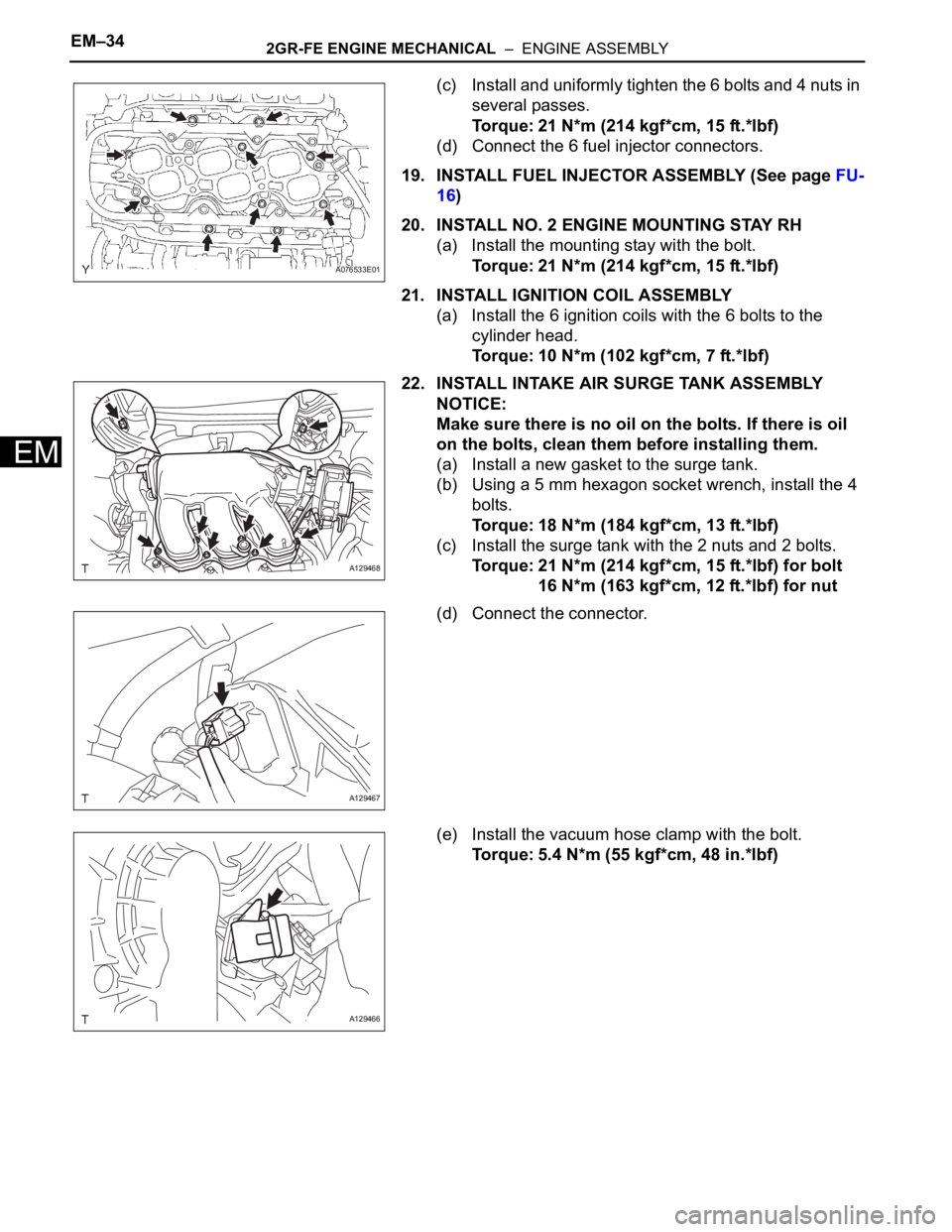
(c) Install and uniformly tighten the 6 bolts and 4 nuts in
several passes.
Torque: 21 N*m (214 kgf*cm, 15 ft.*lbf)
(d) Connect the 6 fuel injector connectors.
19. INSTALL FUEL INJECTOR ASSEMBLY (See page FU-
16)
20. INSTALL NO. 2 ENGINE MOUNTING STAY RH
(a) Install the mounting stay with the bolt.
Torque: 21 N*m (214 kgf*cm, 15 ft.*lbf)
21. INSTALL IGNITION COIL ASSEMBLY
(a) Install the 6 ignition coils with the 6 bolts to the
cylinder head.
Torque: 10 N*m (102 kgf*cm, 7 ft.*lbf)
22. INSTALL INTAKE AIR SURGE TANK ASSEMBLY
NOTICE:
Make sure there is no oil on the bolts. If there is oil
on the bolts, clean them before installing them.
(a) Install a new gasket to the surge tank.
(b) Using a 5 mm hexagon socket wrench, install the 4
bolts.
Torque: 18 N*m (184 kgf*cm, 13 ft.*lbf)
(c) Install the surge tank with the 2 nuts and 2 bolts.
Torque: 21 N*m (214 kgf*cm, 15 ft.*lbf) for bolt
16 N*m (163 kgf*cm, 12 ft.*lbf) for nut
(d) Connect the connector.
(e) Install the vacuum hose clamp with the bolt.
Torque: 5.4 N*m (55 kgf*cm, 48 in.*lbf)
A076533E01
A129468
A129467
A129466
Page 681 of 2000
2GR-FE ENGINE MECHANICAL – ENGINE ASSEMBLYEM–35
EM
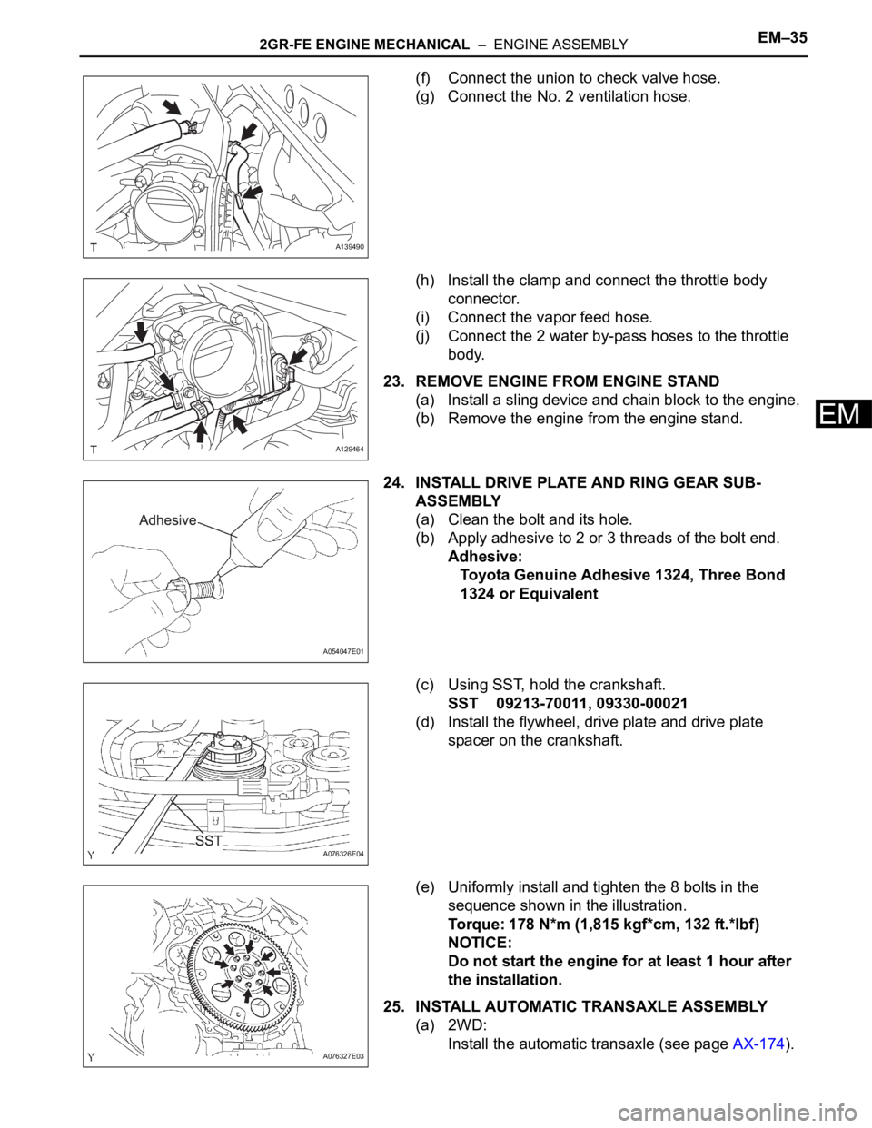
(f) Connect the union to check valve hose.
(g) Connect the No. 2 ventilation hose.
(h) Install the clamp and connect the throttle body
connector.
(i) Connect the vapor feed hose.
(j) Connect the 2 water by-pass hoses to the throttle
body.
23. REMOVE ENGINE FROM ENGINE STAND
(a) Install a sling device and chain block to the engine.
(b) Remove the engine from the engine stand.
24. INSTALL DRIVE PLATE AND RING GEAR SUB-
ASSEMBLY
(a) Clean the bolt and its hole.
(b) Apply adhesive to 2 or 3 threads of the bolt end.
Adhesive:
Toyota Genuine Adhesive 1324, Three Bond
1324 or Equivalent
(c) Using SST, hold the crankshaft.
SST 09213-70011, 09330-00021
(d) Install the flywheel, drive plate and drive plate
spacer on the crankshaft.
(e) Uniformly install and tighten the 8 bolts in the
sequence shown in the illustration.
Torque: 178 N*m (1,815 kgf*cm, 132 ft.*lbf)
NOTICE:
Do not start the engine for at least 1 hour after
the installation.
25. INSTALL AUTOMATIC TRANSAXLE ASSEMBLY
(a) 2WD:
Install the automatic transaxle (see page AX-174).
A139490
A129464
A054047E01
A076326E04
A076327E03
Page 682 of 2000
EM–362GR-FE ENGINE MECHANICAL – ENGINE ASSEMBLY
EM
(b) 4WD:
Install the automatic transaxle (see page AX-175).
26. INSTALL TRANSFER ASSEMBLY (for 4WD) (See
page TF-75)
27. INSTALL STARTER ASSEMBLY (See page ST-14)
28. INSTALL ENGINE WIRE
(a) Install the engine wire to the engine.
29. INSTALL FRONT SUSPENSION CROSSMEMBER
SUB-ASSEMBLY
(a) Attach the engine together with the transaxle to the
suspension crossmember and mounting.
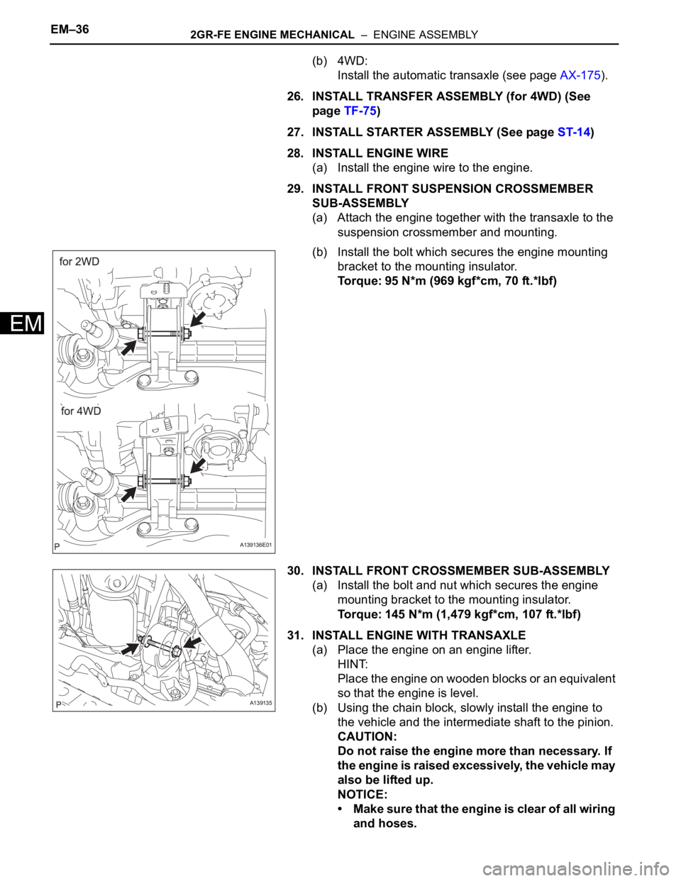
(b) Install the bolt which secures the engine mounting
bracket to the mounting insulator.
Torque: 95 N*m (969 kgf*cm, 70 ft.*lbf)
30. INSTALL FRONT CROSSMEMBER SUB-ASSEMBLY
(a) Install the bolt and nut which secures the engine
mounting bracket to the mounting insulator.
Torque: 145 N*m (1,479 kgf*cm, 107 ft.*lbf)
31. INSTALL ENGINE WITH TRANSAXLE
(a) Place the engine on an engine lifter.
HINT:
Place the engine on wooden blocks or an equivalent
so that the engine is level.
(b) Using the chain block, slowly install the engine to
the vehicle and the intermediate shaft to the pinion.
CAUTION:
Do not raise the engine more than necessary. If
the engine is raised excessively, the vehicle may
also be lifted up.
NOTICE:
• Make sure that the engine is clear of all wiring
and hoses.
A139136E01
A139135
Page 683 of 2000
2GR-FE ENGINE MECHANICAL – ENGINE ASSEMBLYEM–37
EM
• While raising the engine into the vehicle, do
not allow it to contact the vehicle.
• Align the matchmarks on the intermediate
shaft and pinion.
(c) Temporarily install the suspension member and
crossmember with the 10 bolts.
(d) Temporarily install the member brace rear RH and
LH with the 6 bolts.
(e) Install the engine mounting insulator LH with the bolt
and nut.
Torque: 56 N*m (571 kgf*cm, 41 ft.*lbf)
NOTICE:
While holding the bolt in place, tighten the nut.
(f) Install the engine mounting insulator RH with the 2
bolts and 2 nuts.
Torque: 95 N*m (969 kgf*cm, 70 ft.*lbf) for bolt
and nut A
52 N*m (530 kgf*cm, 38 ft.*lbf) for nut B
A123580
A139134
A137896E01
Page 684 of 2000
EM–382GR-FE ENGINE MECHANICAL – ENGINE ASSEMBLY
EM
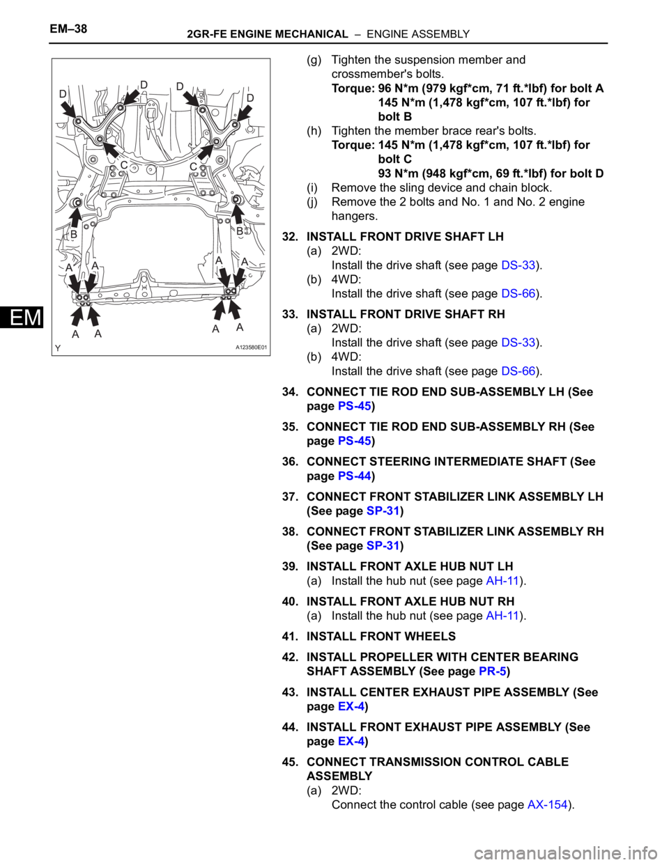
(g) Tighten the suspension member and
crossmember's bolts.
Torque: 96 N*m (979 kgf*cm, 71 ft.*lbf) for bolt A
145 N*m (1,478 kgf*cm, 107 ft.*lbf) for
bolt B
(h) Tighten the member brace rear's bolts.
Torque: 145 N*m (1,478 kgf*cm, 107 ft.*lbf) for
bolt C
93 N*m (948 kgf*cm, 69 ft.*lbf) for bolt D
(i) Remove the sling device and chain block.
(j) Remove the 2 bolts and No. 1 and No. 2 engine
hangers.
32. INSTALL FRONT DRIVE SHAFT LH
(a) 2WD:
Install the drive shaft (see page DS-33).
(b) 4WD:
Install the drive shaft (see page DS-66).
33. INSTALL FRONT DRIVE SHAFT RH
(a) 2WD:
Install the drive shaft (see page DS-33).
(b) 4WD:
Install the drive shaft (see page DS-66).
34. CONNECT TIE ROD END SUB-ASSEMBLY LH (See
page PS-45)
35. CONNECT TIE ROD END SUB-ASSEMBLY RH (See
page PS-45)
36. CONNECT STEERING INTERMEDIATE SHAFT (See
page PS-44)
37. CONNECT FRONT STABILIZER LINK ASSEMBLY LH
(See page SP-31)
38. CONNECT FRONT STABILIZER LINK ASSEMBLY RH
(See page SP-31)
39. INSTALL FRONT AXLE HUB NUT LH
(a) Install the hub nut (see page AH-11).
40. INSTALL FRONT AXLE HUB NUT RH
(a) Install the hub nut (see page AH-11).
41. INSTALL FRONT WHEELS
42. INSTALL PROPELLER WITH CENTER BEARING
SHAFT ASSEMBLY (See page PR-5)
43. INSTALL CENTER EXHAUST PIPE ASSEMBLY (See
page EX-4)
44. INSTALL FRONT EXHAUST PIPE ASSEMBLY (See
page EX-4)
45. CONNECT TRANSMISSION CONTROL CABLE
ASSEMBLY
(a) 2WD:
Connect the control cable (see page AX-154).
A123580E01
Page 685 of 2000
2GR-FE ENGINE MECHANICAL – ENGINE ASSEMBLYEM–39
EM
(b) 4WD:
Connect the control cable (see page AX-154).
46. CONNECT RADIATOR HOSE INLET
47. CONNECT RADIATOR HOSE OUTLET
48. CONNECT OIL COOLER HOSE
49. CONNECT SUCTION HOSE SUB-ASSEMBLY (See
page AC-221)
50. INSTALL DISCHARGE HOSE SUB-ASSEMBLY (See
page AC-221)
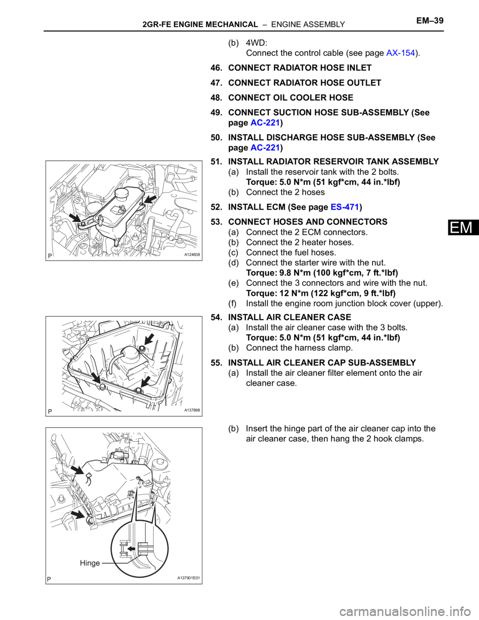
51. INSTALL RADIATOR RESERVOIR TANK ASSEMBLY
(a) Install the reservoir tank with the 2 bolts.
Torque: 5.0 N*m (51 kgf*cm, 44 in.*lbf)
(b) Connect the 2 hoses
52. INSTALL ECM (See page ES-471)
53. CONNECT HOSES AND CONNECTORS
(a) Connect the 2 ECM connectors.
(b) Connect the 2 heater hoses.
(c) Connect the fuel hoses.
(d) Connect the starter wire with the nut.
Torque: 9.8 N*m (100 kgf*cm, 7 ft.*lbf)
(e) Connect the 3 connectors and wire with the nut.
Torque: 12 N*m (122 kgf*cm, 9 ft.*lbf)
(f) Install the engine room junction block cover (upper).
54. INSTALL AIR CLEANER CASE
(a) Install the air cleaner case with the 3 bolts.
Torque: 5.0 N*m (51 kgf*cm, 44 in.*lbf)
(b) Connect the harness clamp.
55. INSTALL AIR CLEANER CAP SUB-ASSEMBLY
(a) Install the air cleaner filter element onto the air
cleaner case.
(b) Insert the hinge part of the air cleaner cap into the
air cleaner case, then hang the 2 hook clamps.
A124838
A137898
A137901E01
Page 686 of 2000
EM–402GR-FE ENGINE MECHANICAL – ENGINE ASSEMBLY
EM
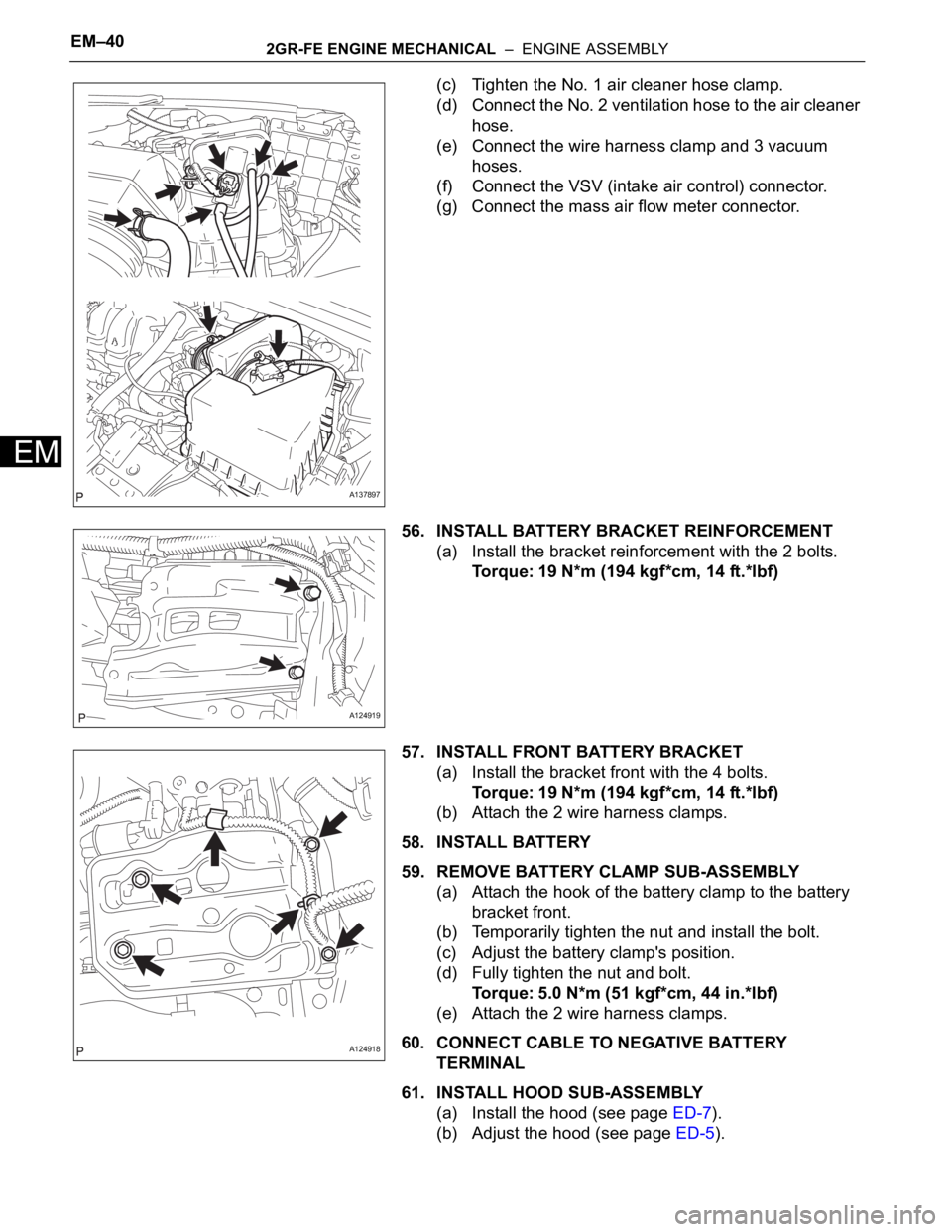
(c) Tighten the No. 1 air cleaner hose clamp.
(d) Connect the No. 2 ventilation hose to the air cleaner
hose.
(e) Connect the wire harness clamp and 3 vacuum
hoses.
(f) Connect the VSV (intake air control) connector.
(g) Connect the mass air flow meter connector.
56. INSTALL BATTERY BRACKET REINFORCEMENT
(a) Install the bracket reinforcement with the 2 bolts.
Torque: 19 N*m (194 kgf*cm, 14 ft.*lbf)
57. INSTALL FRONT BATTERY BRACKET
(a) Install the bracket front with the 4 bolts.
Torque: 19 N*m (194 kgf*cm, 14 ft.*lbf)
(b) Attach the 2 wire harness clamps.
58. INSTALL BATTERY
59. REMOVE BATTERY CLAMP SUB-ASSEMBLY
(a) Attach the hook of the battery clamp to the battery
bracket front.
(b) Temporarily tighten the nut and install the bolt.
(c) Adjust the battery clamp's position.
(d) Fully tighten the nut and bolt.
Torque: 5.0 N*m (51 kgf*cm, 44 in.*lbf)
(e) Attach the 2 wire harness clamps.
60. CONNECT CABLE TO NEGATIVE BATTERY
TERMINAL
61. INSTALL HOOD SUB-ASSEMBLY
(a) Install the hood (see page ED-7).
(b) Adjust the hood (see page ED-5).
A137897
A124919
A124918
Page 687 of 2000
2GR-FE ENGINE MECHANICAL – ENGINE ASSEMBLYEM–41
EM
62. ADD AUTOMATIC TRANSAXLE FLUID
(a) 2WD:
Add automatic transmission fluid (see page AX-
177).
(b) 4WD:
Add automatic transmission fluid (see page AX-
178).
63. ADD TRANSFER OIL (for 4WD) (See page TF-45)
64. ADD ENGINE OIL (See page LU-6)
65. ADD ENGINE COOLANT (See page CO-8)
66. CHARGE REFRIGERANT (See page AC-172)
67. CHECK FOR LEAKAGE OF REFRIGERANT (See
page AC-173)
68. CHECK FOR ENGINE OIL LEAKS (See page LU-6)
69. CHECK FOR ENGINE COOLANT LEAKS (See page
CO-1)
70. CHECK FOR FUEL LEAKS
71. INSPECT EXHAUST GAS LEAKS
72. INSPECT SHIFT LEVER POSITION
(a) 2WD:
Inspect the shift lever position (see page AX-159).
(b) 4WD:
Inspect the shift lever position (see page AX-158).
73. ADJUST TRANSMISSION CONTROL CABLE
(a) 2WD:
Adjust the shift lever position (see page AX-159).
(b) 4WD:
Adjust the shift lever position (see page AX-159).
74. INSTALL FRONT FLOOR COVER (See page FU-39)
75. INSTALL NO. 2 ENGINE UNDER COVER
(a) Install the under cover with the 2 clips.
76. INSTALL REAR ENGINE UNDER COVER LH
(a) Install the under cover with the 2 clips.
77. INSTALL REAR ENGINE UNDER COVER RH
(a) Install the under cover with the 2 clips.
78. INSTALL NO. 1 ENGINE UNDER COVER
(a) Install the under cover with the 4 bolts and 12 clips.