Page 199 of 2000
EM–242GR-FE ENGINE MECHANICAL – ENGINE ASSEMBLY
EM
(b) 4WD:
Disconnect the control cable (see page AX-154).
31. REMOVE FRONT EXHAUST PIPE ASSEMBLY (See
page EX-3)
32. REMOVE CENTER EXHAUST PIPE ASSEMBLY (See
page EX-2)
33. REMOVE PROPELLER WITH CENTER BEARING
SHAFT ASSEMBLY (See page PR-3)
34. REMOVE FRONT WHEELS
35. REMOVE FRONT AXLE HUB NUT LH
(a) Remove the hub nut (see page AH-8).
36. REMOVE FRONT AXLE HUB NUT RH
(a) Remove the hub nut (see page AH-8).
37. DISCONNECT FRONT STABILIZER LINK ASSEMBLY
LH (See page SP-30)
38. DISCONNECT FRONT STABILIZER LINK ASSEMBLY
RH (See page SP-30)
39. DISCONNECT STEERING INTERMEDIATE SHAFT
(See page PS-44)
40. DISCONNECT TIE ROD END SUB-ASSEMBLY RH
(See page PS-42)
41. DISCONNECT TIE ROD END SUB-ASSEMBLY LH
(See page PS-42)
42. REMOVE FRONT DRIVE SHAFT LH
(a) 2WD:
Remove the drive shaft (see page DS-10).
(b) 4WD:
Remove the drive shaft (see page DS-43).
43. REMOVE FRONT DRIVE SHAFT RH
(a) 2WD:
Remove the drive shaft (see page DS-10).
(b) 4WD:
Remove the drive shaft (see page DS-43).
44. REMOVE ENGINE WITH TRANSAXLE
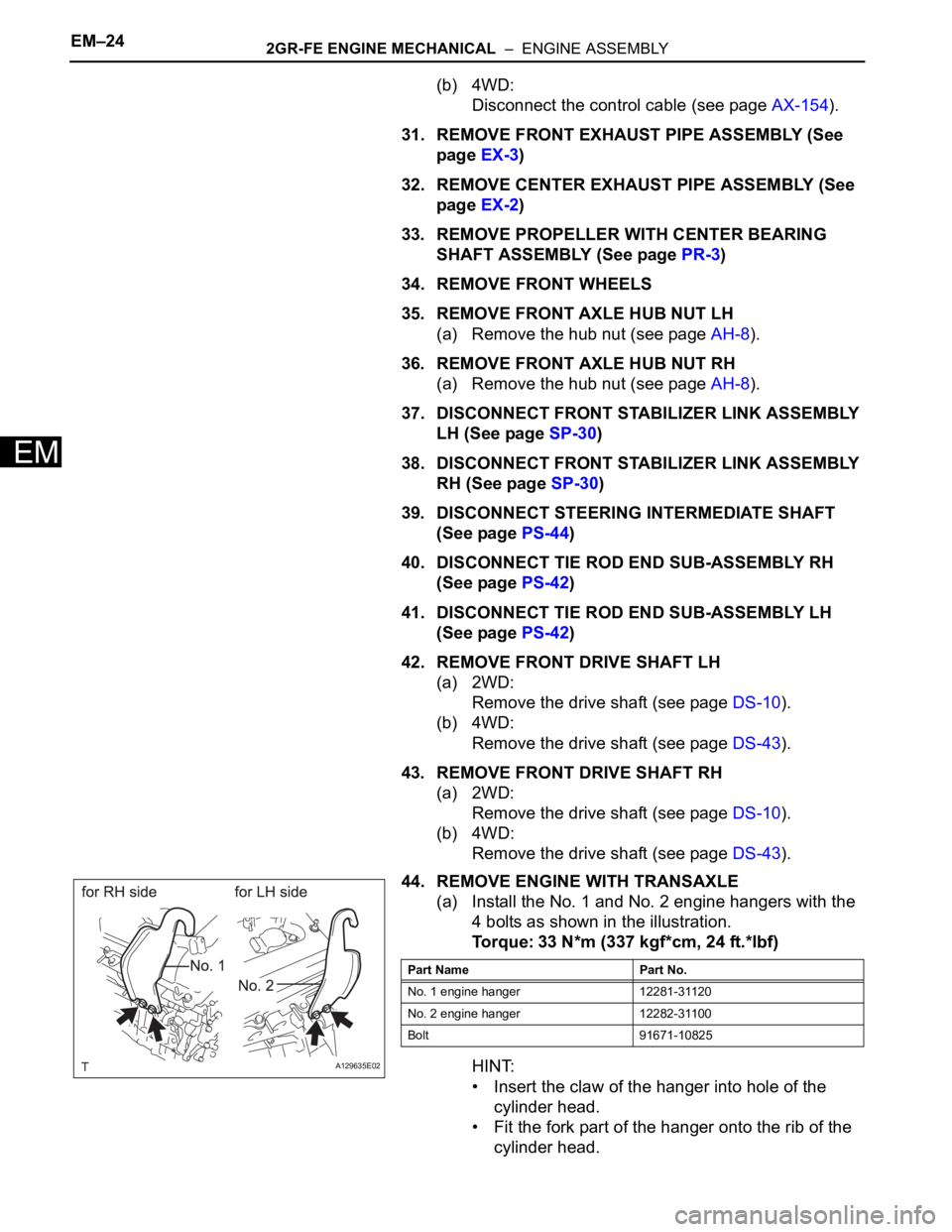
(a) Install the No. 1 and No. 2 engine hangers with the
4 bolts as shown in the illustration.
Torque: 33 N*m (337 kgf*cm, 24 ft.*lbf)
HINT:
• Insert the claw of the hanger into hole of the
cylinder head.
• Fit the fork part of the hanger onto the rib of the
cylinder head.
A129635E02
Part Name Part No.
No. 1 engine hanger 12281-31120
No. 2 engine hanger 12282-31100
Bolt 91671-10825
Page 201 of 2000
EM–262GR-FE ENGINE MECHANICAL – ENGINE ASSEMBLY
EM
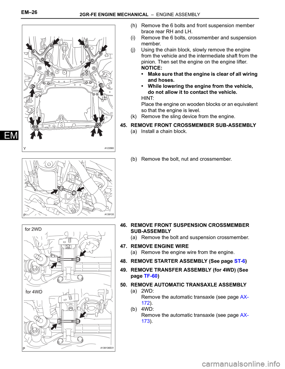
(h) Remove the 6 bolts and front suspension member
brace rear RH and LH.
(i) Remove the 6 bolts, crossmember and suspension
member.
(j) Using the chain block, slowly remove the engine
from the vehicle and the intermediate shaft from the
pinion. Then set the engine on the engine lifter.
NOTICE:
• Make sure that the engine is clear of all wiring
and hoses.
• While lowering the engine from the vehicle,
do not allow it to contact the vehicle.
HINT:
Place the engine on wooden blocks or an equivalent
so that the engine is level.
(k) Remove the sling device from the engine.
45. REMOVE FRONT CROSSMEMBER SUB-ASSEMBLY
(a) Install a chain block.
(b) Remove the bolt, nut and crossmember.
46. REMOVE FRONT SUSPENSION CROSSMEMBER
SUB-ASSEMBLY
(a) Remove the bolt and suspension crossmember.
47. REMOVE ENGINE WIRE
(a) Remove the engine wire from the engine.
48. REMOVE STARTER ASSEMBLY (See page ST-6)
49. REMOVE TRANSFER ASSEMBLY (for 4WD) (See
page TF-60)
50. REMOVE AUTOMATIC TRANSAXLE ASSEMBLY
(a) 2WD:
Remove the automatic transaxle (see page AX-
172).
(b) 4WD:
Remove the automatic transaxle (see page AX-
173).
A123580
A139135
A139136E01
Page 392 of 2000
SERVICE SPECIFICATIONS – GF1A TRANSFERSS–69
SS
TORQUE SPECIFICATIONS
Part Tightened N*m kgf*cm ft.*lbf
Breather oil deflector x transfer
case6.5 66 58
Output shaft x Transfer gear nut 360 3700 266
Driven pinion front bearing x
Transfer case38 390 28
No. 1 transfer case cover x
transfer case47 480 35
Transfer drain plug x transfer
case49 500 36
Transfer drain plug x transfer
case49 500 36
Transfer & Transaxle setting stud
bolt x transfer case39 400 29
Transfer assembly x transaxle 69 700 51
4WD Control ECU x Body 4.5 46 40
Page 393 of 2000
SS–72SERVICE SPECIFICATIONS – DRIVE SHAFT
SS
TORQUE SPECIFICATIONS
(2005/11-2006/01)
Drive shaft
Part Tightened N*m kgf*cm ft.*lbf
Front wheel
Rear wheel103 1,050 76
front suspension lower arm x Lower ball joint 92 938 68
Front axle hub nut 216 2,203 159
Drive shaft bearing bracket x Engine 63.7 650 47
Drive shaft bearing case
bolt2WD 63.7 650 47
Drive shaft bearing
bracket x Drive shaft4WD 32.4 330 24
Page 394 of 2000
SERVICE SPECIFICATIONS – DRIVE SHAFTSS–73
SS
TORQUE SPECIFICATIONS
(2006/01- )
Drive shaft
Part Tightened N*m kgf*cm ft.*lbf
Front wheel
Rear wheel103 1,050 76
front suspension lower arm x Lower ball joint 92 938 68
Front axle hub nut
26 216 2,203 159
30 292 2,978 215
Drive shaft bearing bracket x Engine 63.7 650 47
Drive shaft bearing case
bolt2WD 63.7 650 47
Drive shaft bearing
bracket x Drive shaft4WD 32.4 330 24
Page 419 of 2000
MA–12MAINTENANCE – CHASSIS
MA
GENERAL MAINTENANCE
(2006/01- )
1. INSPECT STEERING LINKAGE AND GEAR HOUSING
(a) Check the steering wheel free play.
(b) Check the steering linkage for looseness or
damage.
(1) Check that the tie rod ends do not have
excessive play.
(2) Check that the dust seals and boots are not
damaged.
(3) Check that the boot clamps are not loose.
(4) Check that the steering gear housing is not
damaged.
(5) Check that the connectors are properly
connected to the steering gear housing.
2. INSPECT BALL JOINTS AND DUST COVERS
(a) Inspect the ball joints for excessive looseness.
(1) Jack up the front of the vehicle and place
wooden blocks with a height of 180 to 200 mm
(7.09 to 7.87 in.) under the front tires.
(2) Lower the vehicle until the front coil spring has
about half its ordinary load. Place stands under
the vehicle for safety.
(3) Check that the front wheels are pointing
straight ahead. Use wheel chocks on all 4
wheels.
(4) Using a lever, pry up the end of the lower arm.
Check the amount of play.
Maximum ball joint vertical play:
0 mm (0 in.)
If there is any play, replace the ball joint.
(b) Check the dust cover for damage.
3. INSPECT DRIVE SHAFT BOOTS
(a) Check the drive shaft boots for loose clamps,
grease leakage, kinks or damage.
4. INSPECT AUTOMATIC TRANSAXLE FLUID LEVEL
(a) Visually check the transmission for fluid leakage. If
oil is leaking, find the cause and repair it.
5. INSPECT TRANSFER OIL (for 4WD)
(a) Visually check the transfer for oil leakage. If oil is
leaking, find the cause and repair it.
6. INSPECT REAR DIFFERENTIAL OIL (for 4WD)
(a) For the rear differential oil inspection, refer to the
following procedures (see page DF-3).
Type See procedures
U151E See page AX-126
U151F See page AX-126
Type See procedures
Front Oil See page TF-45
Rear Oil See page TF-45
Page 633 of 2000
EM–982AZ-FE ENGINE MECHANICAL – ENGINE ASSEMBLY
EM
REMOVAL
1. DISCHARGE FUEL SYSTEM PRESSURE (See page
FU-9)
2. DISCONNECT CABLE FROM NEGATIVE BATTERY
TERMINAL
CAUTION:
Wait at least 90 seconds after disconnecting the
cable from the negative (-) battery terminal to
prevent airbag and seat belt pretensioner activation.
3. REMOVE HOOD SUB-ASSEMBLY (See page ED-4)
4. REMOVE RADIATOR SUPPORT OPENING COVER
5. REMOVE BATTERY CLAMP SUB-ASSEMBLY
(a) Loosen the bolt and nut, and remove the battery
clamp.
6. REMOVE BATTERY
7. REMOVE BATTERY TRAY
8. REMOVE FRONT WHEEL
9. REMOVE NO. 1 ENGINE UNDER COVER
10. REMOVE NO. 2 ENGINE UNDER COVER
11. REMOVE FRONT FENDER APRON RH
12. REMOVE NO. 1 ENGINE COVER (See page EM-22)
13. DRAIN ENGINE COOLANT (See page CO-6)
14. DRAIN AUTOMATIC TRANSAXLE FLUID
(a) Drain automatic transaxle fluid for U241E (2WD)
(see page AX-146).
(b) Drain automatic transaxle fluid for U140F (4WD)
(see page AX-147).
15. REMOVE RADIATOR ASSEMBLY
(a) Remove the radiator (see page CO-29).
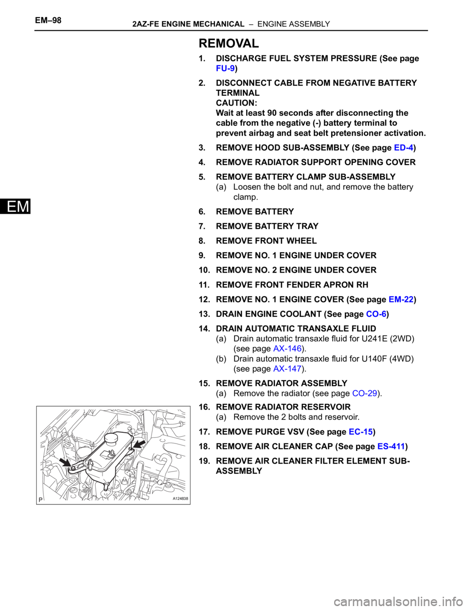
16. REMOVE RADIATOR RESERVOIR
(a) Remove the 2 bolts and reservoir.
17. REMOVE PURGE VSV (See page EC-15)
18. REMOVE AIR CLEANER CAP (See page ES-411)
19. REMOVE AIR CLEANER FILTER ELEMENT SUB-
ASSEMBLY
A124838
Page 635 of 2000
EM–1002AZ-FE ENGINE MECHANICAL – ENGINE ASSEMBLY
EM
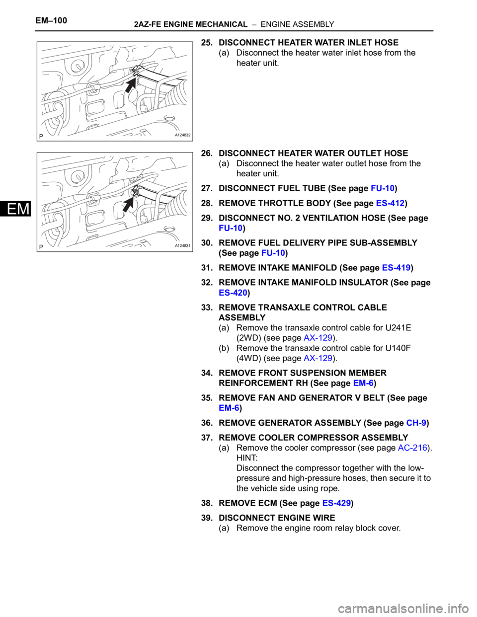
25. DISCONNECT HEATER WATER INLET HOSE
(a) Disconnect the heater water inlet hose from the
heater unit.
26. DISCONNECT HEATER WATER OUTLET HOSE
(a) Disconnect the heater water outlet hose from the
heater unit.
27. DISCONNECT FUEL TUBE (See page FU-10)
28. REMOVE THROTTLE BODY (See page ES-412)
29. DISCONNECT NO. 2 VENTILATION HOSE (See page
FU-10)
30. REMOVE FUEL DELIVERY PIPE SUB-ASSEMBLY
(See page FU-10)
31. REMOVE INTAKE MANIFOLD (See page ES-419)
32. REMOVE INTAKE MANIFOLD INSULATOR (See page
ES-420)
33. REMOVE TRANSAXLE CONTROL CABLE
ASSEMBLY
(a) Remove the transaxle control cable for U241E
(2WD) (see page AX-129).
(b) Remove the transaxle control cable for U140F
(4WD) (see page AX-129).
34. REMOVE FRONT SUSPENSION MEMBER
REINFORCEMENT RH (See page EM-6)
35. REMOVE FAN AND GENERATOR V BELT (See page
EM-6)
36. REMOVE GENERATOR ASSEMBLY (See page CH-9)
37. REMOVE COOLER COMPRESSOR ASSEMBLY
(a) Remove the cooler compressor (see page AC-216).
HINT:
Disconnect the compressor together with the low-
pressure and high-pressure hoses, then secure it to
the vehicle side using rope.
38. REMOVE ECM (See page ES-429)
39. DISCONNECT ENGINE WIRE
(a) Remove the engine room relay block cover.
A124832
A124831