Page 384 of 2000

SS–22SERVICE SPECIFICATIONS – 2GR-FE ENGINE MECHANICAL
SS
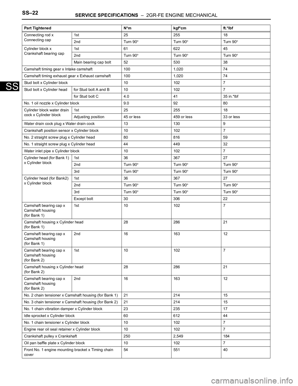
Connecting rod x
Connecting cap1st 25 255 18
2nd Turn 90
Turn 90Turn 90
Cylinder block x
Crankshaft bearing cap1st 61 622 45
2nd Turn 90
Turn 90Turn 90
Main bearing cap bolt 52 530 38
Camshaft timing gear x Intake camshaft 100 1,020 74
Camshaft timing exhaust gear x Exhaust camshaft 100 1,020 74
Stud bolt x Cylinder block 10 102 7
Stud bolt x Cylinder head for Stud bolt A and B 10 102 7
for Stud bolt C 4.0 41 35 in.*lbf
No. 1 oil nozzle x Cylinder block 9.0 92 80
Cylinder block water drain
cock x Cylinder block1st 25 255 18
Adjusting position 45 or less 459 or less 33 or less
Water drain cock plug x Water drain cock 13 130 9
Crankshaft position sensor x Cylinder block 10 102 7
No. 2 straight screw plug x Cylinder head 80 816 59
No. 1 straight screw plug x Cylinder head 44 449 32
Water inlet pipe x Cylinder block 10 102 7
Cylinder head (for Bank 1)
x Cylinder block1st 36 367 27
2nd Turn 90
Turn 90Turn 90
3rd Turn 90Turn 90Turn 90
Cylinder head (for Bank2)
x Cylinder block1st 36 367 27
2nd Turn 90
Turn 90Turn 90
3rd Turn 90Turn 90Turn 90
Except bolt 30 306 22
Camshaft bearing cap x
Camshaft housing
(for Bank 1)1st 10 102 7
Camshaft housing x Cylinder head
(for Bank 1)28 286 21
Camshaft bearing cap x
Camshaft housing
(for Bank 1)2nd 16 163 12
Camshaft bearing cap x
Camshaft housing
(for Bank 2)1st 10 102 7
Camshaft housing x Cylinder head
(for Bank 2)28 286 21
Camshaft bearing cap x
Camshaft housing
(for Bank 2)2nd 16 163 12
No. 2 chain tensioner x Camshaft housing (for Bank 1) 21 214 15
No. 3 chain tensioner x Camshaft housing (for Bank 2) 21 214 15
No. 1 chain vibration damper x Cylinder block 23 235 17
Idle sprocket x Cylinder block 60 612 44
No. 1 chain tensioner x Cylinder block 10 102 7
Engine rear oil seal retainer x Cylinder block 10 102 7
Crankshaft pulley x Crankshaft 250 2,549 184
Oil pan baffle plate x Cylinder block 10 102 7
Front No. 1 engine mounting bracket x Timing chain
cover54 551 40 Part Tightened N*m kgf*cm ft.*lbf
Page 385 of 2000
SERVICE SPECIFICATIONS – 2GR-FE ENGINE MECHANICALSS–23
SS
Cylinder head cover x
Cylinder head
(for Bank 1)for Bolt A 21 214 15
for Except bolt A 10 102 7
Oil pipe bracket x Cylinder head (for Bank 1) 10 102 7
Oil pipe union bolt x Cylinder head cover
(for Bank 1)65 663 48
Oil pipe union bolt x Cylinder head
(for Bank 1)65 663 48
Cylinder head cover x
Cylinder headfor Bolt A 21 214 15
for Except bolt A 10 102 7
No. 1 oil pipe union bolt x Cylinder head cover (for Bank
2)65 663 48
No. 1 oil pipe union bolt x Cylinder head (for Bank 2) 65 663 48
Water outlet x Cylinder head 10 102 7
Camshaft timing oil control valve x Cylinder head cover 10 102 7
VVT sensor x Cylinder head cover 10 102 7
Spark plug x Cylinder head 18 184 13 Part Tightened N*m kgf*cm ft.*lbf
Page 518 of 2000
2GR-FE ENGINE CONTROL SYSTEM – SFI SYSTEMES–7
ES
SYSTEM DIAGRAM
A136181E02
Page 519 of 2000
ES–82GR-FE ENGINE CONTROL SYSTEM – SFI SYSTEM
ES
A136182E01
Page 520 of 2000
2GR-FE ENGINE CONTROL SYSTEM – SFI SYSTEMES–9
ES
A136183E01
Page 521 of 2000
ES–102GR-FE ENGINE CONTROL SYSTEM – SFI SYSTEM
ES
A136184E01
Page 535 of 2000
2GR-FE ENGINE CONTROL SYSTEM – SFI SYSTEMES–11
ES
HOW TO PROCEED WITH
TROUBLESHOOTING
HINT:
*: Use the intelligent tester.
NEXT
NEXT
HINT:
If the display indicates a communication fault in the tester,
inspect the DLC3.
NEXT
HINT:
Record or print DTCs and freeze frame data, if necessary.
NEXT
NEXT
NEXT
NEXT
1VEHICLE BROUGHT TO WORKSHOP
2CUSTOMER PROBLEM ANALYSIS
3CONNECT INTELLIGENT TESTER TO DLC3*
4CHECK DTC AND FREEZE FRAME DATA*
5CLEAR DTC AND FREEZE FRAME DATA*
6CONDUCT VISUAL INSPECTION
7SET CHECK MODE DIAGNOSIS*
Page 536 of 2000
ES–122GR-FE ENGINE CONTROL SYSTEM – SFI SYSTEM
ES
HINT:
If the engine does not start, first perform the "CHECK DTC"
procedures and "CONDUCT BASIC INSPECTION"
procedures below.
B
A
NEXT
B
A
NEXT
B
A
8CONFIRM PROBLEM SYMPTOMS
Result Proceed to
Malfunction does not occur A
Malfunction occurs B
GO TO STEP 10
9SIMULATE SYMPTOMS
10CHECK DTC*
Result Proceed to
Malfunction code A
No code B
GO TO STEP 12
11REFER TO DTC CHART
GO TO STEP 14
12CONDUCT BASIC INSPECTION
Result Proceed to
Malfunctioning parts not confirmed A
Malfunctioning parts confirmed B
GO TO STEP 17