2006 SUZUKI SX4 oil temperature
[x] Cancel search: oil temperaturePage 1041 of 1556
Downloaded from www.Manualslib.com manuals search engine Air Bag System: 8B-2
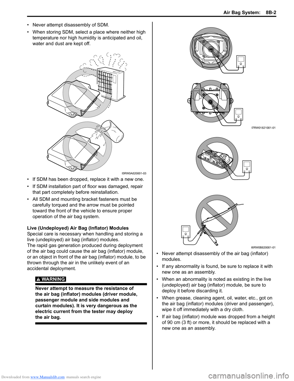
• Never attempt disassembly of SDM.
• When storing SDM, select a place where neither high
temperature nor high humidity is anticipated and oil,
water and dust are kept off.
• If SDM has been dropped, replace it with a new one.
• If SDM installation part of floor was damaged, repair
that part completely before reinstallation.
• All SDM and mounting bracket fasteners must be
carefully torqued and the arrow must be pointed
toward the front of the vehicle to ensure proper
operation of the air bag system.
Live (Undeployed) Air Bag (Inflator) Modules
Special care is necessary when handling and storing a
live (undeployed) air bag (inflator) modules.
The rapid gas generation produced during deployment
of the air bag could cause the air bag (inflator) module,
or an object in front of the air bag (inflator) module, to be
thrown through the air in the unlikely event of an
accidental deployment.
WARNING!
Never attempt to measure the resistance of
the air bag (inflator) modules (driver module,
passenger module and side modules and
curtain modules). It is very dangerous as the
electric current from the tester may deploy
the air bag.
• Never attempt disassembly of the air bag (inflator)
modules.
• If any abnormality is found, be sure to replace it with
new one as an assembly.
• When an abnormality is noted as existing in the live
(undeployed) air bag (inflator) module, be sure to
deploy it before discarding it.
• When grease, cleaning agent, oil, water, etc., got on
the air bag (inflator) modules (driver and passenger),
wipe it off immediately with a dry cloth.
• If air bag (inflator) module was dropped from a height
of 90 cm (3 ft) or more, it should be replaced with a
new one as an assembly.
I5RW0A820001-03
I7RW01821001-01
I6RW0B820001-01
Page 1043 of 1556
Downloaded from www.Manualslib.com manuals search engine Air Bag System: 8B-4
• Never attempt to disassemble the seat belt
pretensioners (retractor assembly).
• If any abnormality is found, be sure to replace it with
new one as an assembly.
• When an abnormality is noted as existing in the live
(inactivated) seat belt pretensioner, be sure to activate
it before discarding it.
• When grease, cleaning agent oil, water, etc., got on
the seat belt pretensioners (retractor assembly), wipe
it off immediately with a dry cloth.
• If seat belt pretensioner was dropped from a height of
30 cm (1 ft) or more, it should be replaced with a new
one as an assembly.
WARNING!
• For handling and storage of a live seat belt
pretensioner, select a place where the
ambient temperature below 65 °C (150 °F),
without high humidity and away from
electric noise.
• Never carry the seat belt pretensioner by
webbing.
• When placing a live seat belt pretensioner
on the workbench or other surface, be sure
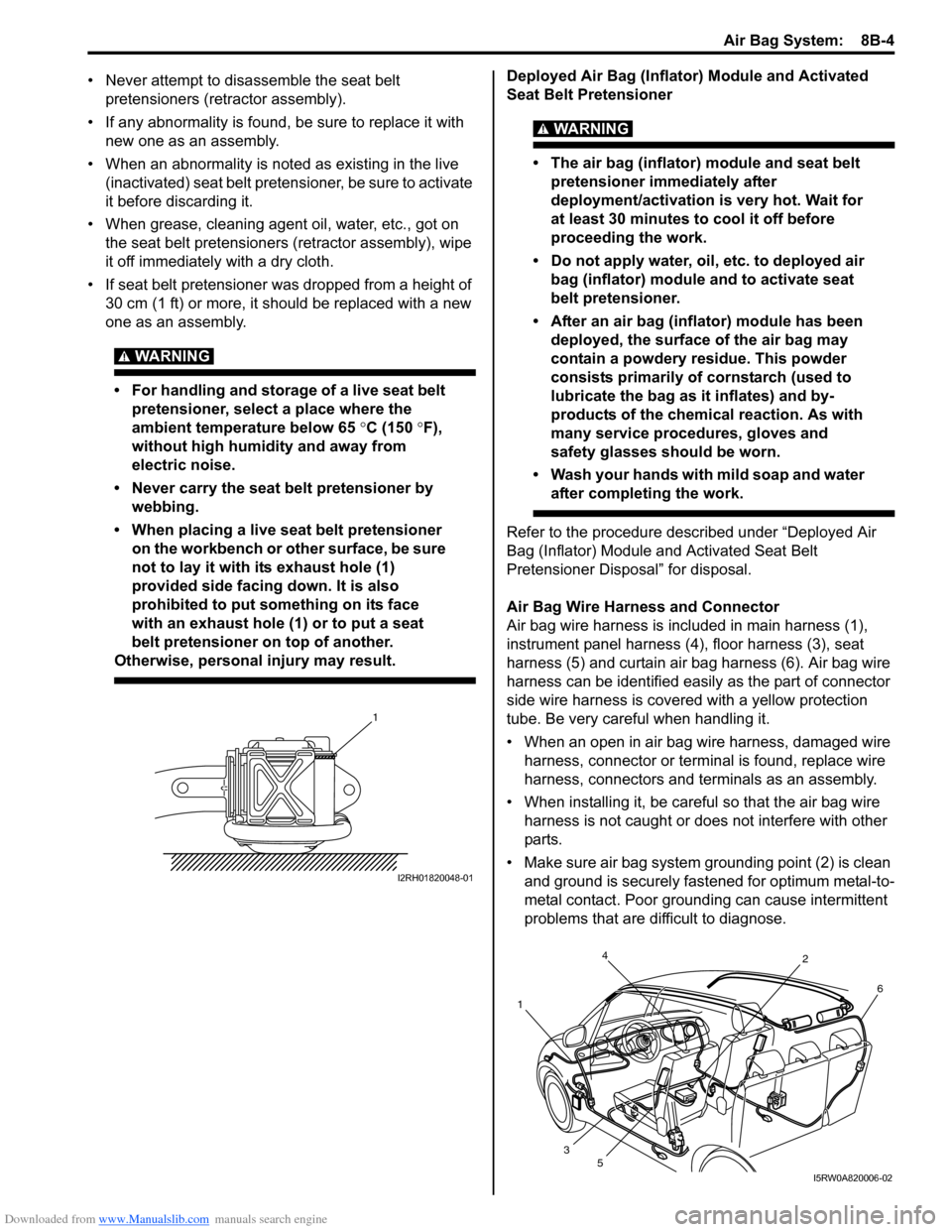
not to lay it with its exhaust hole (1)
provided side facing down. It is also
prohibited to put something on its face
with an exhaust hole (1) or to put a seat
belt pretensioner on top of another.
Otherwise, personal injury may result.
Deployed Air Bag (Inflator) Module and Activated
Seat Belt Pretensioner
WARNING!
• The air bag (inflator) module and seat belt
pretensioner immediately after
deployment/activation is very hot. Wait for
at least 30 minutes to cool it off before
proceeding the work.
• Do not apply water, oil, etc. to deployed air
bag (inflator) module and to activate seat
belt pretensioner.
• After an air bag (inflator) module has been
deployed, the surface of the air bag may
contain a powdery residue. This powder
consists primarily of cornstarch (used to
lubricate the bag as it inflates) and by-
products of the chemical reaction. As with
many service procedures, gloves and
safety glasses should be worn.
• Wash your hands with mild soap and water
after completing the work.
Refer to the procedure described under “Deployed Air
Bag (Inflator) Module and Activated Seat Belt
Pretensioner Disposal” for disposal.
Air Bag Wire Harness and Connector
Air bag wire harness is included in main harness (1),
instrument panel harness (4), floor harness (3), seat
harness (5) and curtain air bag harness (6). Air bag wire
harness can be identified easily as the part of connector
side wire harness is covered with a yellow protection
tube. Be very careful when handling it.
• When an open in air bag wire harness, damaged wire
harness, connector or terminal is found, replace wire
harness, connectors and terminals as an assembly.
• When installing it, be careful so that the air bag wire
harness is not caught or does not interfere with other
parts.
• Make sure air bag system grounding point (2) is clean
and ground is securely fastened for optimum metal-to-
metal contact. Poor grounding can cause intermittent
problems that are difficult to diagnose.
1
I2RH01820048-01
4
12
6
3
5
I5RW0A820006-02
Page 1163 of 1556
Downloaded from www.Manualslib.com manuals search engine Table of Contents 9-iii
Headlight Bulb Replacement (Discharge
Headlight Model) ............................................. 9B-19
Ballast Removal and Installation (Discharge
Headlight Model) ............................................. 9B-19
Igniter Removal and Installation (Discharge
Headlight Model) ............................................. 9B-20
Headlight Aiming Adjustment with Screen ........ 9B-20
Headlight Switch (in Lighting Switch)
Removal and Installation................................. 9B-22
Headlight Switch (in Lighting Switch)
Inspection........................................................ 9B-22
Hazard Warning Switch Removal and
Installation ....................................................... 9B-23
Hazard Warning Switch Inspection ................... 9B-23
Brake Light Switch Inspection ........................... 9B-23
Turn Signal Light Switch (in Lighting Switch)
Removal and Installation................................. 9B-24
Turn Signal Light Switch (in Lighting Switch)
Inspection........................................................ 9B-24
Turn Signal and Hazard Warning Relay
Removal and Installation................................. 9B-24
Turn Signal and Hazard Warning Relay
Inspection........................................................ 9B-25
License Light Assembly Removal and
Installation ....................................................... 9B-25
Front Fog Light Assembly Removal and
Installation (If Equipped) ................................. 9B-26
Front Fog Light Switch Inspection (If
Equipped)........................................................ 9B-26
Front Fog Light Aiming Adjustment with
Screen (If Equipped) ....................................... 9B-26
Rear Fog Light Switch Inspection (If
Equipped)........................................................ 9B-27
Headlight Manual Levering Switch Inspection
(If Equipped) ................................................... 9B-28
Headlight Leveling Actuator Inspection (If
Equipped)........................................................ 9B-28
Height Sensor Removal and Installation (If
Equipped)........................................................ 9B-29
Height Sensor and Its Circuit Inspection (If
Equipped)........................................................ 9B-30
Headlight Leveling Control Module Removal
and Installation (If Equipped) .......................... 9B-30
Initialization of Headlight Auto Leveling
System ............................................................ 9B-30
Auto-On Headlight Sensor Inspection (If
Equipped)........................................................ 9B-31
Illumination Cancel Switch Inspection (If
Equipped)........................................................ 9B-32
Tail Light Relay, Headlight Relay, Front Fog
Light Relay Inspection (If Equipped) ............... 9B-32
Specifications..................................................... 9B-33
Tightening Torque Specifications ...................... 9B-33
Instrumentation / Driver Info. / Horn ...... 9C-1
Precautions........................................................... 9C-1
Precautions in Diagnosing Troubles for
Combination Meter............................................ 9C-1
General Description ............................................. 9C-1
CAN Communication System Description........... 9C-1Auto Volume Control System Description (If
Equipped) ..........................................................9C-3
Schematic and Routing Diagram ........................9C-4
Combination Meter Circuit Diagram ....................9C-4
Component Location ...........................................9C-5
Audio System Component Location ....................9C-5
Diagnostic Information and Procedures ............9C-6
Speedometer and VSS Symptom Diagnosis ......9C-6
Tachometer Symptom Diagnosis ........................9C-6
Engine Coolant Temperature (ECT) Meter
Symptom Diagnosis ..........................................9C-6
Fuel Meter Symptom Diagnosis ..........................9C-6
Low Fuel Warning Light Symptom Diagnosis .....9C-7
Oil Pressure Warning Light Symptom
Diagnosis ..........................................................9C-7
Brake and Parking Brake Warning Light
Symptom Diagnosis ..........................................9C-8
Seat Belt Reminder Light Symptom Diagnosis ....9C-8
A/T Shift Position Indicator Symptom
Diagnosis (A/T Model).......................................9C-8
Charge Warning Light Symptom Diagnosis ........9C-9
Main Beam (High Beam) Indicator Symptom
Diagnosis ..........................................................9C-9
Warning Buzzer Circuit Symptom Diagnosis ......9C-9
Cigarette Lighter Symptom Diagnosis (If
Equipped) ........................................................9C-10
Horn Symptom Diagnosis .................................9C-10
Information Display Symptom Diagnosis (If
Equipped) ........................................................9C-10
Clock System Diagnosis (If Equipped) ..............9C-11
Audio System Symptom Diagnosis (If
Equipped) ........................................................9C-12
Remote Audio Control Switch Symptom
Diagnosis (If Equipped) ...................................9C-13
Navigation Symptom Diagnosis (If Equipped)...9C-13
Repair Instructions ............................................9C-14
Ignition Switch Removal and Installation...........9C-14
Ignition Switch Inspection..................................9C-14
Combination Meter Removal and Installation ...9C-14
Fuel Level Sensor Removal and Installation .....9C-15
Fuel Level Sensor Inspection ............................9C-15
Oil Pressure Switch Removal and Installation ..9C-15
Oil Pressure Switch Inspection .........................9C-15
Engine Coolant Temperature (ECT) Sensor
Inspection ........................................................9C-16
Brake Fluid Level Switch Inspection .................9C-16
Parking Brake Switch Inspection.......................9C-16
Door Switch (Front / Rear Door) Inspection ......9C-16
Rear End Door Switch Inspection .....................9C-16
Outside Air Temperature Sensor Removal
and Installation (If Equipped) ..........................9C-17
Outside Air Temperature Sensor Inspection
(If Equipped)....................................................9C-17
Instrument Panel Removal and Installation.......9C-17
Information Display (Clock) Removal and
Installation .......................................................9C-18
Audio Unit Removal and Installation (If
Equipped) ........................................................9C-19
Page 1188 of 1556
Downloaded from www.Manualslib.com manuals search engine 9A-21 Wiring Systems:
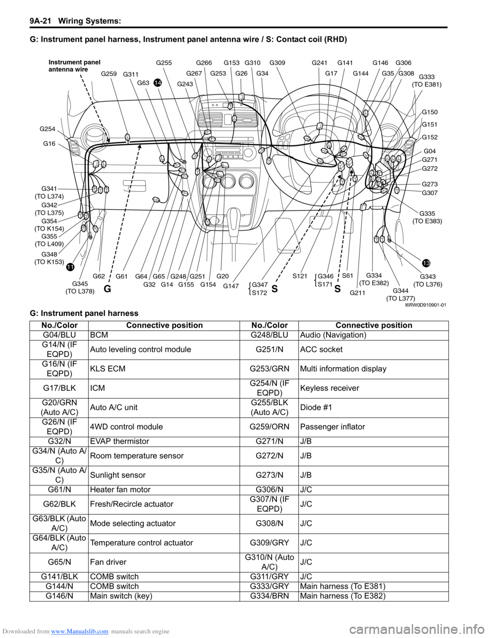
G: Instrument panel harness, Instrument panel antenna wire / S: Contact coil (RHD)
G: Instrument panel harness
G146G141G309
G34G26G253
G266G255
G144
G241
G17
G310G153
G248
G311
G61
G259
1311
14
G16
G341
(TO L374)
G354
(TO K154)
G342
(TO L375)
G348
(TO K153)
G254
G152
G04
G271
G272
G307
G211
G343
(TO L376)
G344
(TO L377) G147G345
(TO L378)
G334
(TO E382)
G333
(TO E381)
G20
S121S61
G32 G155 G154
G63
G62G65G64G273
G151
G150
G308
G306
G35
G251
G347
S172
G346
S171
GSS
Instrument panel
antenna wire
G243
G267
G14
G355
(TO L409)G335
(TO E383)
I6RW0D910901-01
No./Color Connective position No./Color Connective position
G04/BLU BCM G248/BLU Audio (Navigation)
G14/N (IF
EQPD)Auto leveling control module G251/N ACC socket
G16/N (IF
EQPD)KLS ECM G253/GRN Multi information display
G17/BLK ICMG254/N (IF
EQPD)Keyless receiver
G20/GRN
(Auto A/C)Auto A/C unitG255/BLK
(Auto A/C)Diode #1
G26/N (IF
EQPD)4WD control module G259/ORN Passenger inflator
G32/N EVAP thermistor G271/N J/B
G34/N (Auto A/
C)Room temperature sensor G272/N J/B
G35/N (Auto A/
C)Sunlight sensor G273/N J/B
G61/N Heater fan motor G306/N J/C
G62/BLK Fresh/Recircle actuatorG307/N (IF
EQPD)J/C
G63/BLK (Auto
A/C)Mode selecting actuator G308/N J/C
G64/BLK (Auto
A/C)Temperature control actuator G309/GRY J/C
G65/N Fan driverG310/N (Auto
A/C)J/C
G141/BLK COMB switch G311/GRY J/C
G144/N COMB switch G333/GRY Main harness (To E381)
G146/N Main switch (key) G334/BRN Main harness (To E382)
Page 1190 of 1556
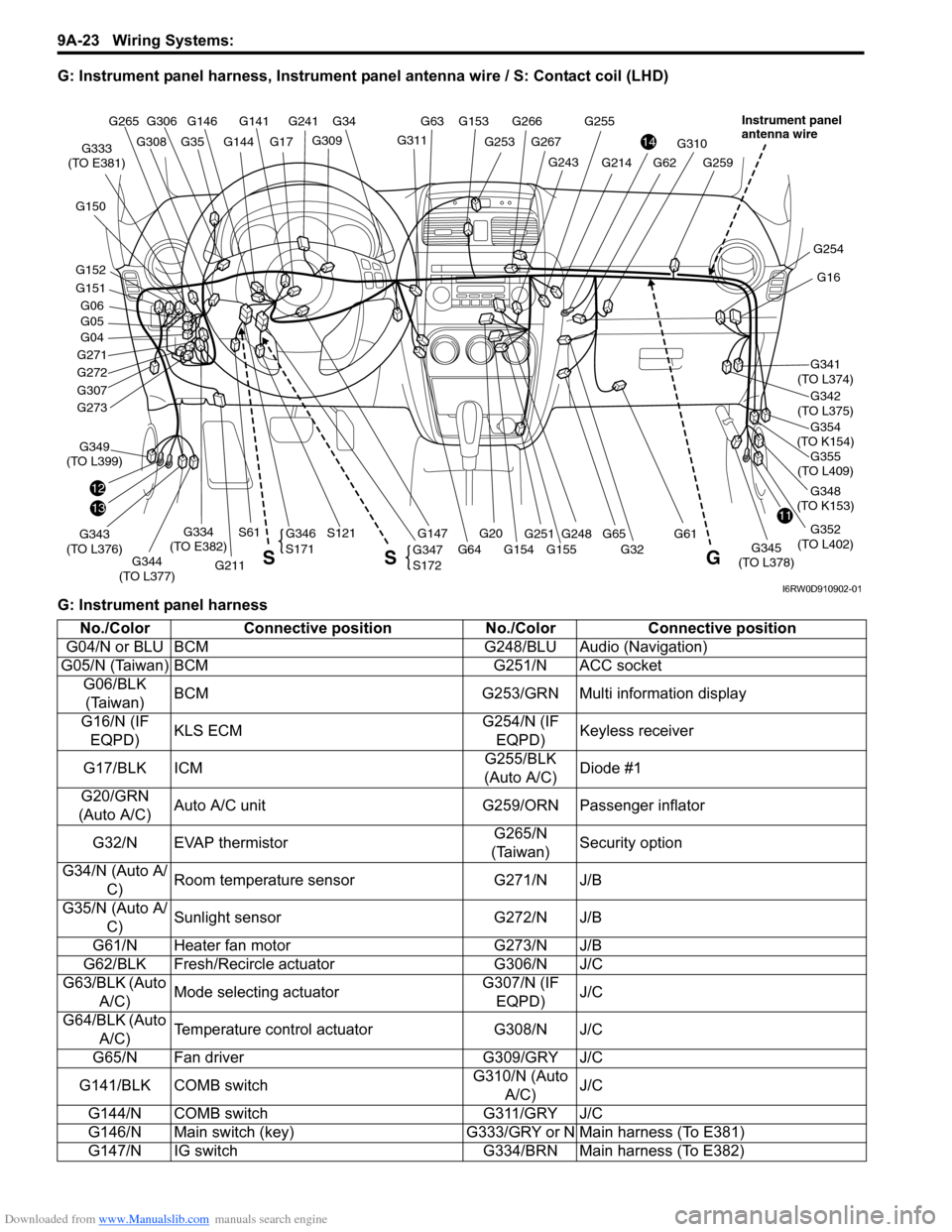
Downloaded from www.Manualslib.com manuals search engine 9A-23 Wiring Systems:
G: Instrument panel harness, Instrument panel antenna wire / S: Contact coil (LHD)
G: Instrument panel harness
G146G141
G309
G34
G253
G266G255
G144
G241
G17G311
G153 G63
G248
G310
G61
G259G243
G267
G355
(TO L409)
1311
14
G16
G341
(TO L374)
G354
(TO K154)
G342
(TO L375)
G348
(TO K153)
G352
(TO L402)
G254
G04
G271
G272
G307
12
G211
G343
(TO L376)G349
(TO L399)
G344
(TO L377)G147G345
(TO L378)
G334
(TO E382)
G333
(TO E381)
G20
S121S61
G32 G155 G154 G64
G62G214
G65 G273
G151
G152 G150
G05 G06
G308
G306 G265
G35
G251
G347
S172
G346
S171
G S S
Instrument panel
antenna wire
I6RW0D910902-01
No./Color Connective position No./Color Connective position
G04/N or BLU BCM G248/BLU Audio (Navigation)
G05/N (Taiwan) BCM G251/N ACC socket
G06/BLK
(Taiwan)BCM G253/GRN Multi information display
G16/N (IF
EQPD)KLS ECMG254/N (IF
EQPD)Keyless receiver
G17/BLK ICMG255/BLK
(Auto A/C)Diode #1
G20/GRN
(Auto A/C)Auto A/C unit G259/ORN Passenger inflator
G32/N EVAP thermistorG265/N
(Taiwan)Security option
G34/N (Auto A/
C)Room temperature sensor G271/N J/B
G35/N (Auto A/
C)Sunlight sensor G272/N J/B
G61/N Heater fan motor G273/N J/B
G62/BLK Fresh/Recircle actuator G306/N J/C
G63/BLK (Auto
A/C)Mode selecting actuatorG307/N (IF
EQPD)J/C
G64/BLK (Auto
A/C)Temperature control actuator G308/N J/C
G65/N Fan driver G309/GRY J/C
G141/BLK COMB switchG310/N (Auto
A/C)J/C
G144/N COMB switch G311/GRY J/C
G146/N Main switch (key) G333/GRY or N Main harness (To E381)
G147/N IG switch G334/BRN Main harness (To E382)
Page 1244 of 1556
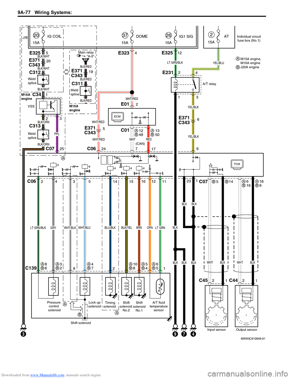
Downloaded from www.Manualslib.com manuals search engine 9A-77 Wiring Systems:
TCM
Lock up
solenoidA/T fluid
temperature
sensorShift
solenoid
No.2Shift
solenoid
No.1
11 12
C1391 2 9
BLK/YELBRNORN
15 4
25
WHT/BLU
Pressure
control
solenoid
LT GRN/BLKGRY
Shift solenoid
LT GRN
ECM
WHTREDWHT/RED
PPL
WHT/RED
BLK/WHT
BLK/RED
BLK/RED
BLK/RED
BLK/WHT
BLK/WHT
5
E371
C343
E371
C34320
E371
C34319
C01
BLKBLKBLK
BLKBLK
E3234E3255
WHT/RED
24 C0625C07717
23116
E012
J/B
15ADOME
37
15AIG COIL
20
15AAT
2
6
3
WHT/BLK
LT GRN/BLK
Timing
solenoid
BLU/BLK
14
WHTBLK
514
2
1C45
Input sensor
C07
WHTBLK
2
1C44
Output sensor
C06
E231
1
3 2
4
YEL/BLU
10AIG1 SIG
26
E32512
BLK
A/T relay
(CAN)
YEL/BLK
7934
E371
C3436
YEL/BLK
Individual circuit
fuse box (No.1)
12
49AB13
50AB
6
16ABBB16
6AB
6
5AB5
4AB4
7AB3
2AB8
6AB10
8AB
A
A
A
B
Weld
splice
M16A
engine
M15A
engine
C312
Weld
splice
C311
BLK/ORN
BLK/ORN
Weld
splice
C313
VSS
1C34
23
"A-5"Main relay
BRM15A engine,
M16A engine
J20A engine A
B
I6RW0C910949-01
Page 1247 of 1556
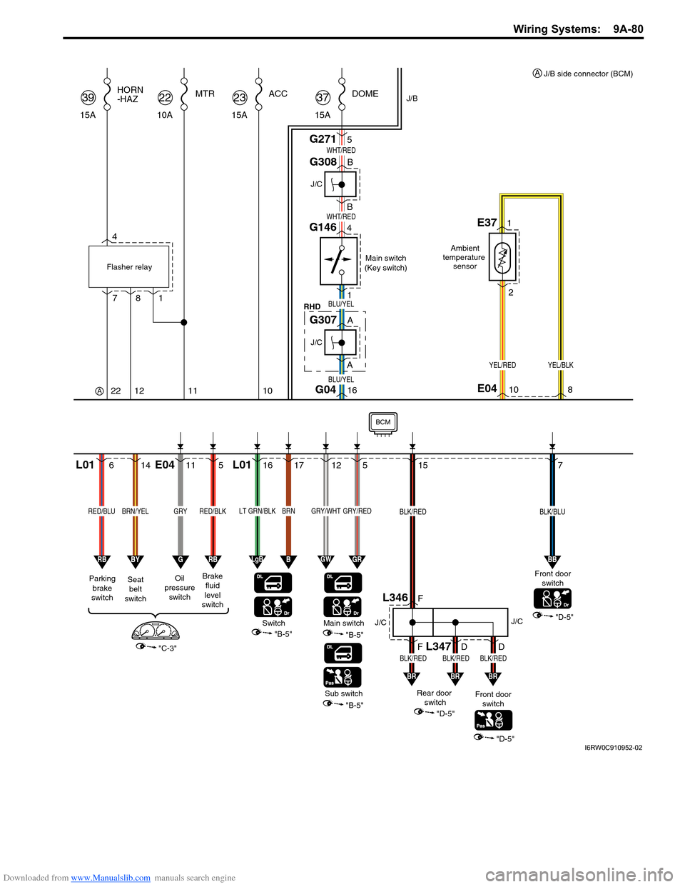
Downloaded from www.Manualslib.com manuals search engine Wiring Systems: 9A-80
15 7
"D-5"
16 BBG0410
BLU/YEL
BLU/YEL
J/C
G308
G146
1 47 4
Main switch
(Key switch)
RHD Flasher relay
DOME
G2715 15A
37ACC MTR
15A23
228
1
12
HORN
-HAZ
15A39
11
10A
22
WHT/RED
WHT/RED
YEL/REDYEL/BLK
1E37
2
Ambient
temperature
sensor
"B-5" Switch
614
1617125
RED/BLUBRN/YELLT GRN/BLKBRNGRY/WHTGRY/RED
Parking
brake
switchSeat
belt
switch
"C-3"
RBBY
115
RED/BLK
BB
Oil
pressure
switchBrake
fluid
level
switch
GRB
L01 L01E04
10E048
LgBBGWGR
Main switch
"B-5"
Sub switch
"B-5"
Front door
switch
Front door
switch
"D-5"
BRBR
BLK/BLUBLK/RED
BLK/REDBLK/REDBLK/RED
J/B
FF
Rear door
switch
"D-5"
BR
DD
J/CJ/C
L346
L347
AA
J/C
G307
BCM
GRY
J/B side connector (BCM) A
A
I6RW0C910952-02
Page 1251 of 1556
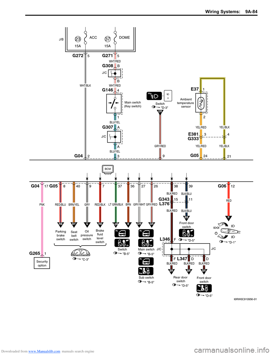
Downloaded from www.Manualslib.com manuals search engine Wiring Systems: 9A-84
38 39
"D-5""D-1"
BLK/BLU
3 AA BBG042
BLU/YEL
BLU/YEL
J/C
G307
1G265
J/C
G308
G146
1 4
Main switch
(Key switch)
DOME
G2715 15A
37ACC
G2725 15A
23
WHT/REDWHT/BLK
WHT/RED
YEL/RED
YEL/RED
YEL/BLK
YEL/BLK
1E37
2
Ambient
temperature
sensor
"B-5" Switch
840
37362726
RED/BLUBRN/YELLT GRN/BLKBRNGRY/WHTGRY/RED
Parking
brake
switchSeat
belt
switch
"C-3"
RBBY
97
RED/BLK
BB
GR
Oil
pressure
switchBrake
fluid
level
switch
Security
option
GRB
G05G0617
PNK
G04
24
GRY/RED
9G0521
LgBBGWGR
Main switch
"B-5"
Sub switch
"B-5"
Front door
switch
"D-3"Switch
Front door
switch
"D-5"
BRBR
BLK/RED
R
12
RED
BLK/BLUBLK/RED
BLK/REDBLK/REDBLK/RED
J/B
FF
Rear door
switch
"D-5"
BR
DD
J/CJ/C
L346
L347
BCM
GRY
E381
G33334
G343
L3761511
I6RW0C910956-01