2006 SUZUKI SX4 display
[x] Cancel search: displayPage 996 of 1556

Downloaded from www.Manualslib.com manuals search engine 7B-56 Air Conditioning System: Automatic Type
Scan Tool Data Definitions
TEMP CONT SWITCH: (Temperature control selector
position, Max Cool, °C / °F, Max Hot): This
parameter indicates the selected position of
temperature control selector.
CABIN TEMPERATURE: (In-car temperature, °C, °F):
This parameter indicates the in-car temperature
detected by inside air temperature sensor.OUTSIDE AIR TEMP (Outside air temperature, °C,
°F): This parameter indicates the outside air
temperature detected by outside air temperature
sensor.
EVAPORATOR TEMP (Evaporator temperature, °C,
°F): This parameter indicates the temperature of air
passed through evaporator.
COOLANT TEMP (Engine Coolant Temperature °C,
°F): This parameter indicates the engine coolant
temperature detected by engine coolant temperature
sensor. �) COOLANT TEMP
Ignition switch turned ONEngine coolant temperature is
displayed
�) SUN LOAD Reference value depends on the situation 0 W/m
2 – 1988 W/m2
�)MODE CONT
SWITCHIgnition switch turned ON and air flow selector at
AUTO positionAUTO (Selected position of air flow
selector is displayed)
�) FAN CONT SWITCHIgnition switch turned ON and blower speed selector
at AUTO positionAUTO (Selected position of blower
speed selector is displayed)
�) FAN DESIRED VOLTIgnition switch turned ON and blower speed selector
at HighApprox. 12.0 V
Ignition switch turned ON and blower speed selector
at LowApprox. 4.0 V
�) AIR MIX POS SENIgnition switch turned ON and temperature selector
at maximum cool positionApprox. 0.5 V
Ignition switch turned ON and temperature selector
at maximum hot positionApprox. 4.5 V
�)MODE POS SENSORIgnition switch turned ON and air flow selector at
DEF positionApprox. 4.5 V
Ignition switch turned ON and air flow selector at
VENT positionApprox. 0.5 V
�) A/C CONT SIGA/C switch turned ON, blower speed selector at other
than OFF position with engine runningON
A/C switch turned OFF with engine running OFF
�) BLOWER LOAD SIGIgnition switch turned ON, blower speed selector at
other than OFF positionON
Ignition switch turned ON, blower speed selector at
OFF positionOFF
�) AIR INTAKE MODEIgnition switch turned ON and air intake selector at
fresh air (FRE) positionFRE
Ignition switch turned ON and air intake selector at
recirculation air (REC) positionREC
Ignition switch turned ON, air flow selector and
blower speed selector at AUTO positionAUTO
�) REFRIGERANT
PRESSUREA/C ON (A/C is operating) with engine running at
ambient temperature 30 °C (86 °F)1130 – 1560 kPa (For details, refer to
pressure of high pressure gauge
under “A/C System Performance
Inspection”)
A/C OFF (A/C is not operating) with engine running
at ambient temperature 30 °C (86 °F) and engine
coolant temperature 90 °C (194 °F) – 100 °C (212
°F)600 – 1000 kPa after longer than 10
minute for A/C switch turned off
�) A/C COMP CLUTCHA/C switch turned ON, blower speed selector at other
than OFF position with engine runningON
A/C switch turned OFF with engine running OFF
�) VEHICLE SPEED At stop with ignition switch turned ON 0 km/h (0 mph)
�) ENGINE TYPE Ignition switch turned ON Engine type is displayed.
�) METER SPEC Ignition switch turned ONCombination meter spec is displayed. Scan Tool Data ConditionNormal Condition / Reference
Va l u e
Page 1010 of 1556
Downloaded from www.Manualslib.com manuals search engine 7B-70 Air Conditioning System: Automatic Type
DTC B1546: A/C Refrigerant Pressure MalfunctionS6RW0D7224019
DTC Detecting Condition and Trouble Area
DTC Troubleshooting
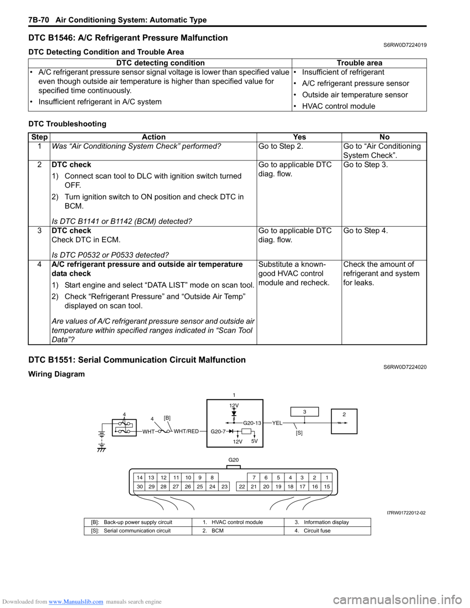
DTC B1551: Serial Communication Circuit MalfunctionS6RW0D7224020
Wiring DiagramDTC detecting condition Trouble area
• A/C refrigerant pressure sensor signal voltage is lower than specified value
even though outside air temperature is higher than specified value for
specified time continuously.
• Insufficient refrigerant in A/C system• Insufficient of refrigerant
• A/C refrigerant pressure sensor
• Outside air temperature sensor
• HVAC control module
Step Action Yes No
1Was “Air Conditioning System Check” performed?Go to Step 2. Go to “Air Conditioning
System Check”.
2DTC check
1) Connect scan tool to DLC with ignition switch turned
OFF.
2) Turn ignition switch to ON position and check DTC in
BCM.
Is DTC B1141 or B1142 (BCM) detected?Go to applicable DTC
diag. flow.Go to Step 3.
3DTC check
Check DTC in ECM.
Is DTC P0532 or P0533 detected?Go to applicable DTC
diag. flow.Go to Step 4.
4A/C refrigerant pressure and outside air temperature
data check
1) Start engine and select “DATA LIST” mode on scan tool.
2) Check “Refrigerant Pressure” and “Outside Air Temp”
displayed on scan tool.
Are values of A/C refrigerant pressure sensor and outside air
temperature within specified ranges indicated in “Scan Tool
Data”?Substitute a known-
good HVAC control
module and recheck.Check the amount of
refrigerant and system
for leaks.
12V
G20
G20-13YEL
1 2 3 4 5 6 7 8 9 10 11 12 13 14
15 16 17 18 19 20 21 24 23 22 25 26 27 28 29 30
1
2 3
[S]WHT/REDWHTG20-7
12V5V
[B]4 4
I7RW01722012-02
[B]: Back-up power supply circuit 1. HVAC control module 3. Information display
[S]: Serial communication circuit 2. BCM 4. Circuit fuse
Page 1011 of 1556
Downloaded from www.Manualslib.com manuals search engine Air Conditioning System: Automatic Type 7B-71
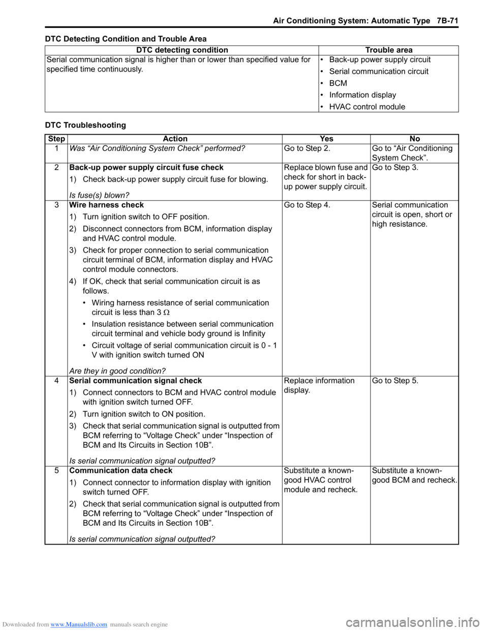
DTC Detecting Condition and Trouble Area
DTC TroubleshootingDTC detecting condition Trouble area
Serial communication signal is higher than or lower than specified value for
specified time continuously.• Back-up power supply circuit
• Serial communication circuit
•BCM
• Information display
• HVAC control module
Step Action Yes No
1Was “Air Conditioning System Check” performed?Go to Step 2. Go to “Air Conditioning
System Check”.
2Back-up power supply circuit fuse check
1) Check back-up power supply circuit fuse for blowing.
Is fuse(s) blown?Replace blown fuse and
check for short in back-
up power supply circuit.Go to Step 3.
3Wire harness check
1) Turn ignition switch to OFF position.
2) Disconnect connectors from BCM, information display
and HVAC control module.
3) Check for proper connection to serial communication
circuit terminal of BCM, information display and HVAC
control module connectors.
4) If OK, check that serial communication circuit is as
follows.
• Wiring harness resistance of serial communication
circuit is less than 3 Ω
• Insulation resistance between serial communication
circuit terminal and vehicle body ground is Infinity
• Circuit voltage of serial communication circuit is 0 - 1
V with ignition switch turned ON
Are they in good condition?Go to Step 4. Serial communication
circuit is open, short or
high resistance.
4Serial communication signal check
1) Connect connectors to BCM and HVAC control module
with ignition switch turned OFF.
2) Turn ignition switch to ON position.
3) Check that serial communication signal is outputted from
BCM referring to “Voltage Check” under “Inspection of
BCM and Its Circuits in Section 10B”.
Is serial communication signal outputted?Replace information
display.Go to Step 5.
5Communication data check
1) Connect connector to information display with ignition
switch turned OFF.
2) Check that serial communication signal is outputted from
BCM referring to “Voltage Check” under “Inspection of
BCM and Its Circuits in Section 10B”.
Is serial communication signal outputted?Substitute a known-
good HVAC control
module and recheck.Substitute a known-
good BCM and recheck.
Page 1012 of 1556
Downloaded from www.Manualslib.com manuals search engine 7B-72 Air Conditioning System: Automatic Type
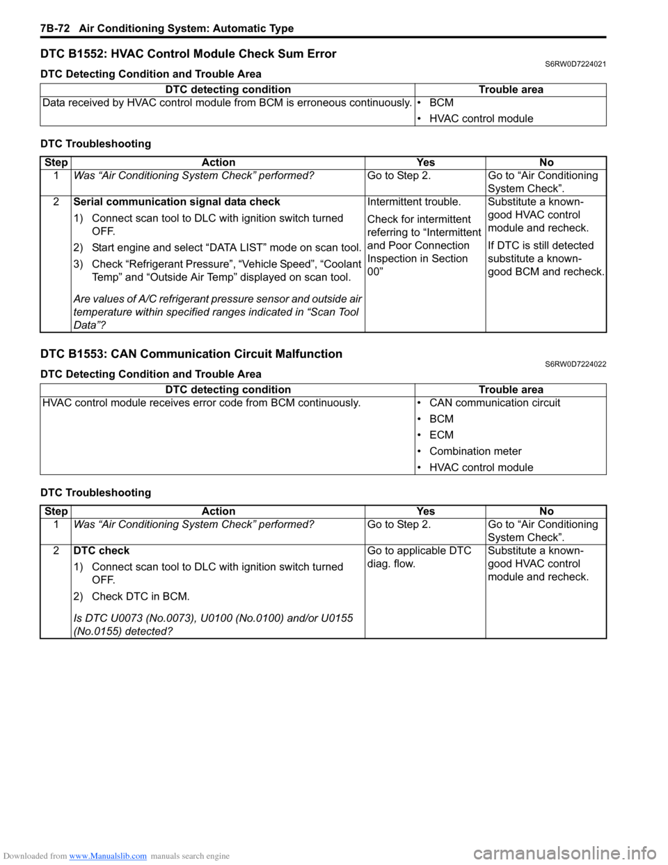
DTC B1552: HVAC Control Module Check Sum ErrorS6RW0D7224021
DTC Detecting Condition and Trouble Area
DTC Troubleshooting
DTC B1553: CAN Communication Circuit MalfunctionS6RW0D7224022
DTC Detecting Condition and Trouble Area
DTC TroubleshootingDTC detecting condition Trouble area
Data received by HVAC control module from BCM is erroneous continuously. • BCM
• HVAC control module
Step Action Yes No
1Was “Air Conditioning System Check” performed?Go to Step 2. Go to “Air Conditioning
System Check”.
2Serial communication signal data check
1) Connect scan tool to DLC with ignition switch turned
OFF.
2) Start engine and select “DATA LIST” mode on scan tool.
3) Check “Refrigerant Pressure”, “Vehicle Speed”, “Coolant
Temp” and “Outside Air Temp” displayed on scan tool.
Are values of A/C refrigerant pressure sensor and outside air
temperature within specified ranges indicated in “Scan Tool
Data”?Intermittent trouble.
Check for intermittent
referring to “Intermittent
and Poor Connection
Inspection in Section
00”Substitute a known-
good HVAC control
module and recheck.
If DTC is still detected
substitute a known-
good BCM and recheck.
DTC detecting condition Trouble area
HVAC control module receives error code from BCM continuously. • CAN communication circuit
•BCM
•ECM
• Combination meter
• HVAC control module
Step Action Yes No
1Was “Air Conditioning System Check” performed?Go to Step 2. Go to “Air Conditioning
System Check”.
2DTC check
1) Connect scan tool to DLC with ignition switch turned
OFF.
2) Check DTC in BCM.
Is DTC U0073 (No.0073), U0100 (No.0100) and/or U0155
(No.0155) detected?Go to applicable DTC
diag. flow.Substitute a known-
good HVAC control
module and recheck.
Page 1015 of 1556
Downloaded from www.Manualslib.com manuals search engine Air Conditioning System: Automatic Type 7B-75
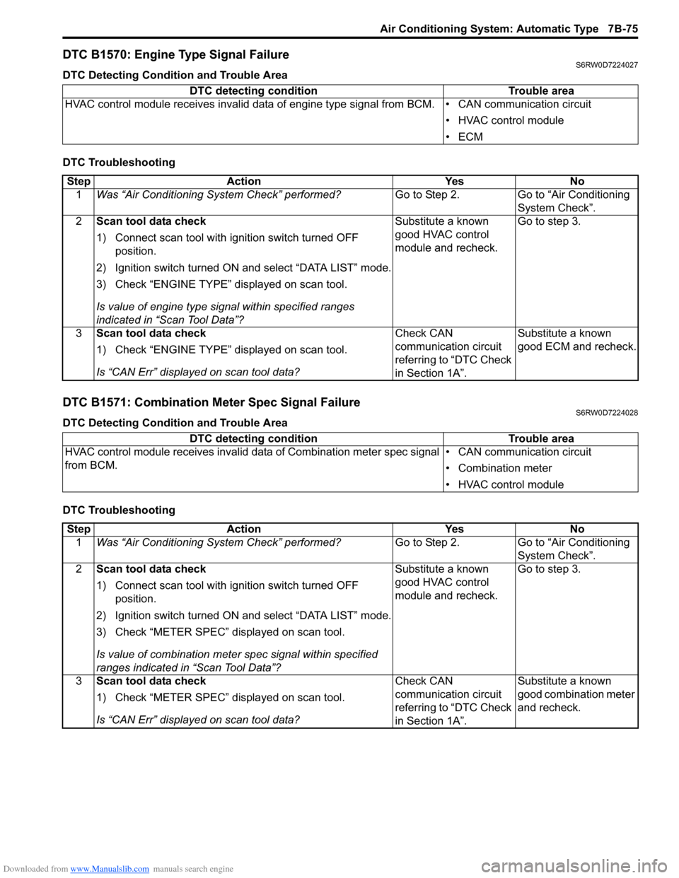
DTC B1570: Engine Type Signal FailureS6RW0D7224027
DTC Detecting Condition and Trouble Area
DTC Troubleshooting
DTC B1571: Combination Meter Spec Signal FailureS6RW0D7224028
DTC Detecting Condition and Trouble Area
DTC TroubleshootingDTC detecting condition Trouble area
HVAC control module receives invalid data of engine type signal from BCM. • CAN communication circuit
• HVAC control module
•ECM
Step Action Yes No
1Was “Air Conditioning System Check” performed?Go to Step 2. Go to “Air Conditioning
System Check”.
2Scan tool data check
1) Connect scan tool with ignition switch turned OFF
position.
2) Ignition switch turned ON and select “DATA LIST” mode.
3) Check “ENGINE TYPE” displayed on scan tool.
Is value of engine type signal within specified ranges
indicated in “Scan Tool Data”?Substitute a known
good HVAC control
module and recheck.Go to step 3.
3Scan tool data check
1) Check “ENGINE TYPE” displayed on scan tool.
Is “CAN Err” displayed on scan tool data?Check CAN
communication circuit
referring to “DTC Check
in Section 1A”.Substitute a known
good ECM and recheck.
DTC detecting condition Trouble area
HVAC control module receives invalid data of Combination meter spec signal
from BCM.• CAN communication circuit
• Combination meter
• HVAC control module
Step Action Yes No
1Was “Air Conditioning System Check” performed?Go to Step 2. Go to “Air Conditioning
System Check”.
2Scan tool data check
1) Connect scan tool with ignition switch turned OFF
position.
2) Ignition switch turned ON and select “DATA LIST” mode.
3) Check “METER SPEC” displayed on scan tool.
Is value of combination meter spec signal within specified
ranges indicated in “Scan Tool Data”?Substitute a known
good HVAC control
module and recheck.Go to step 3.
3Scan tool data check
1) Check “METER SPEC” displayed on scan tool.
Is “CAN Err” displayed on scan tool data?Check CAN
communication circuit
referring to “DTC Check
in Section 1A”.Substitute a known
good combination meter
and recheck.
Page 1052 of 1556
Downloaded from www.Manualslib.com manuals search engine 8B-13 Air Bag System:
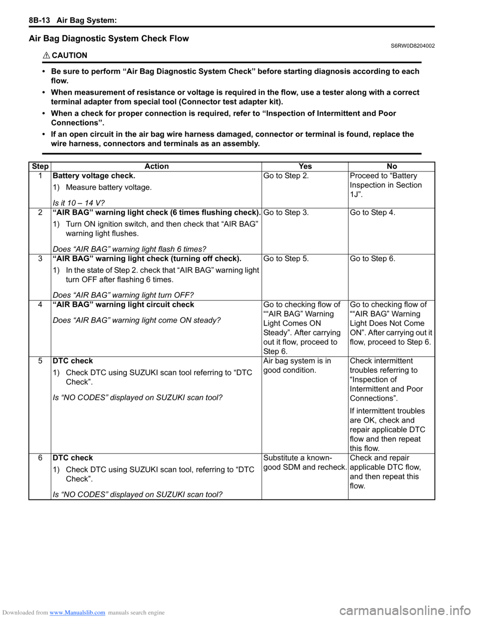
Air Bag Diagnostic System Check FlowS6RW0D8204002
CAUTION!
• Be sure to perform “Air Bag Diagnostic System Check” before starting diagnosis according to each
flow.
• When measurement of resistance or voltage is required in the flow, use a tester along with a correct
terminal adapter from special tool (Connector test adapter kit).
• When a check for proper connection is required, refer to “Inspection of Intermittent and Poor
Connections”.
• If an open circuit in the air bag wire harness damaged, connector or terminal is found, replace the
wire harness, connectors and terminals as an assembly.
Step Action Yes No
1Battery voltage check.
1) Measure battery voltage.
Is it 10 – 14 V?Go to Step 2. Proceed to “Battery
Inspection in Section
1J”.
2“AIR BAG” warning light check (6 times flushing check).
1) Turn ON ignition switch, and then check that “AIR BAG”
warning light flushes.
Does “AIR BAG” warning light flash 6 times?Go to Step 3. Go to Step 4.
3“AIR BAG” warning light check (turning off check).
1) In the state of Step 2. check that “AIR BAG” warning light
turn OFF after flashing 6 times.
Does “AIR BAG” warning light turn OFF?Go to Step 5. Go to Step 6.
4“AIR BAG” warning light circuit check
Does “AIR BAG” warning light come ON steady?Go to checking flow of
““AIR BAG” Warning
Light Comes ON
Steady”. After carrying
out it flow, proceed to
St ep 6 .Go to checking flow of
““AIR BAG” Warning
Light Does Not Come
ON”. After carrying out it
flow, proceed to Step 6.
5DTC check
1) Check DTC using SUZUKI scan tool referring to “DTC
Check”.
Is “NO CODES” displayed on SUZUKI scan tool?Air bag system is in
good condition.Check intermittent
troubles referring to
“Inspection of
Intermittent and Poor
Connections”.
If intermittent troubles
are OK, check and
repair applicable DTC
flow and then repeat
this flow.
6DTC check
1) Check DTC using SUZUKI scan tool, referring to “DTC
Check”.
Is “NO CODES” displayed on SUZUKI scan tool?Substitute a known-
good SDM and recheck.Check and repair
applicable DTC flow,
and then repeat this
flow.
Page 1057 of 1556
Downloaded from www.Manualslib.com manuals search engine Air Bag System: 8B-18
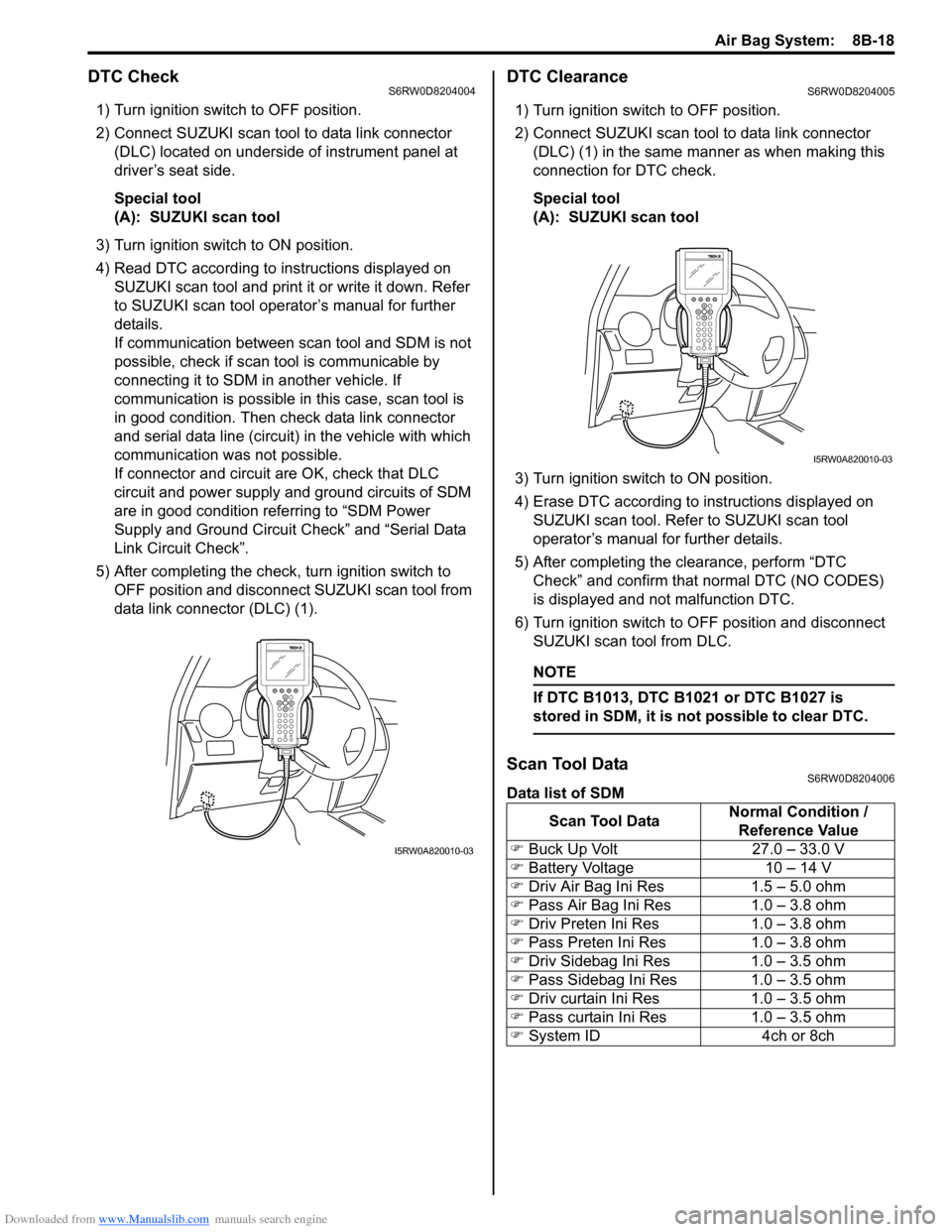
DTC CheckS6RW0D8204004
1) Turn ignition switch to OFF position.
2) Connect SUZUKI scan tool to data link connector
(DLC) located on underside of instrument panel at
driver’s seat side.
Special tool
(A): SUZUKI scan tool
3) Turn ignition switch to ON position.
4) Read DTC according to instructions displayed on
SUZUKI scan tool and print it or write it down. Refer
to SUZUKI scan tool operator’s manual for further
details.
If communication between scan tool and SDM is not
possible, check if scan tool is communicable by
connecting it to SDM in another vehicle. If
communication is possible in this case, scan tool is
in good condition. Then check data link connector
and serial data line (circuit) in the vehicle with which
communication was not possible.
If connector and circuit are OK, check that DLC
circuit and power supply and ground circuits of SDM
are in good condition referring to “SDM Power
Supply and Ground Circuit Check” and “Serial Data
Link Circuit Check”.
5) After completing the check, turn ignition switch to
OFF position and disconnect SUZUKI scan tool from
data link connector (DLC) (1).
DTC ClearanceS6RW0D8204005
1) Turn ignition switch to OFF position.
2) Connect SUZUKI scan tool to data link connector
(DLC) (1) in the same manner as when making this
connection for DTC check.
Special tool
(A): SUZUKI scan tool
3) Turn ignition switch to ON position.
4) Erase DTC according to instructions displayed on
SUZUKI scan tool. Refer to SUZUKI scan tool
operator’s manual for further details.
5) After completing the clearance, perform “DTC
Check” and confirm that normal DTC (NO CODES)
is displayed and not malfunction DTC.
6) Turn ignition switch to OFF position and disconnect
SUZUKI scan tool from DLC.
NOTE
If DTC B1013, DTC B1021 or DTC B1027 is
stored in SDM, it is not possible to clear DTC.
Scan Tool DataS6RW0D8204006
Data list of SDM
I5RW0A820010-03
Scan Tool DataNormal Condition /
Reference Value
�) Buck Up Volt 27.0 – 33.0 V
�) Battery Voltage 10 – 14 V
�) Driv Air Bag Ini Res 1.5 – 5.0 ohm
�) Pass Air Bag Ini Res 1.0 – 3.8 ohm
�) Driv Preten Ini Res 1.0 – 3.8 ohm
�) Pass Preten Ini Res 1.0 – 3.8 ohm
�) Driv Sidebag Ini Res 1.0 – 3.5 ohm
�) Pass Sidebag Ini Res 1.0 – 3.5 ohm
�) Driv curtain Ini Res 1.0 – 3.5 ohm
�) Pass curtain Ini Res 1.0 – 3.5 ohm
�) System ID 4ch or 8ch
I5RW0A820010-03
Page 1162 of 1556
Downloaded from www.Manualslib.com manuals search engine 9-ii Table of Contents
B-9 Keyless Start System Circuit Diagram...... 9A-103
C-1 Combination Meter Circuit Diagram
(Meter) .......................................................... 9A-104
C-2 Combination Meter Circuit Diagram
(Indicator) ...................................................... 9A-105
C-3 Combination Meter Circuit Diagram
(Warning Light) ............................................. 9A-106
D-1 Headlight System Circuit Diagram
(Except Taiwan) ............................................ 9A-108
D-1 Headlight System Circuit Diagram
(Taiwan) ........................................................ 9A-110
D-2 Position, Tail and Licence Plate Light
System Circuit Diagram (Except Taiwan) ..... 9A-111
D-2 Position, Tail and Licence Plate Light
System Circuit Diagram (Taiwan) ................. 9A-112
D-3 Front Fog Light System Circuit Diagram
(Except Taiwan) ............................................ 9A-113
D-3 Front Fog Light System Circuit Diagram
(Taiwan) ........................................................ 9A-114
D-4 Illumination Light System Circuit Diagram
(Except Taiwan) ............................................ 9A-115
D-4 Illumination Light System Circuit Diagram
(Taiwan) ........................................................ 9A-116
D-5 Interior Light System Circuit Diagram
(Except Taiwan) ............................................ 9A-117
D-5 Interior Light System Circuit Diagram
(Taiwan) ........................................................ 9A-118
D-6 Turn Signal and Hazard Warning Light
System Circuit Diagram (Except Taiwan) ..... 9A-119
D-6 Turn Signal and Hazard Warning Light
System Circuit Diagram (Taiwan) ................. 9A-121
D-7 Brake Light System Circuit Diagram ........ 9A-123
D-8 Back-Up Light System Circuit Diagram .... 9A-124
D-9 Headlight Beam Leveling System Circuit
Diagram (Manual Leveling)........................... 9A-125
D-10 Rear Fog Light Circuit Diagram .............. 9A-126
E-1 Heater System Circuit Diagram ................ 9A-127
E-2 Auto A/C System Circuit Diagram ............ 9A-129
F-1 Air-Bag System Circuit Diagram (4ch) ...... 9A-131
F-1 Air-Bag System Circuit Diagram (8ch) ...... 9A-132
F-2 Anti-Lock Brake System Circuit Diagram.. 9A-134
F-4 Power Steering System Circuit Diagram .. 9A-136
G-1 Audio System Circuit Diagram ................. 9A-138
G-2 Multi Information Display / Accessory
Socket System Circuit Diagram .................... 9A-140
G-4 Navigation System Circuit Diagram ......... 9A-141
List of Connector .............................................9A-143
List of Connectors ........................................... 9A-143
C Connector .................................................... 9A-143
E Connector .................................................... 9A-145
G Connector .................................................... 9A-146
J Connector ..................................................... 9A-149
K Connector .................................................... 9A-149
L Connector..................................................... 9A-150
O Connector .................................................... 9A-152
Q Connector (8ch)........................................... 9A-152
R Connector .................................................... 9A-152
S Connector .................................................... 9A-152
Lighting Systems .................................... 9B-1
Precautions ...........................................................9B-1
Precautions for Discharge Headlight Service
(If Equipped)...................................................... 9B-1
Precautions in Diagnosing Troubles
(Headlight Auto Leveling System) ..................... 9B-1
General Description .............................................9B-1
Discharge Headlight Description (If
Equipped) .......................................................... 9B-1
Headlight Auto Leveling System Description
(If Equipped)...................................................... 9B-2
Auto-On Headlight System Description (If
Equipped) .......................................................... 9B-4
Schematic and Routing Diagram ........................9B-5
Headlight Auto Leveling System Wiring
Circuit Diagram ................................................. 9B-5
Component Location ...........................................9B-6
Lighting System Components Location............... 9B-6
Interior Light System Location............................. 9B-7
Diagnostic Information and Procedures ............9B-7
Self-Diagnosis Function for Headlight Auto
Leveling System ................................................ 9B-7
Headlight Leveling Warning Light Check ............ 9B-8
Headlight Symptom Diagnosis (Discharge
Headlight Model) ............................................... 9B-8
Headlight Symptom diagnosis (Other than
Discharge Headlight Model) .............................. 9B-9
Auto-On Headlight System Symptom
Diagnosis (If Equipped) ..................................... 9B-9
DRL System Symptom Diagnosis (If
Equipped) ........................................................ 9B-10
Headlight Auto Leveling System Symptom
Diagnosis (If Equipped) ................................... 9B-10
Headlight Manual Leveling System Symptom
Diagnosis (If Equipped) ................................... 9B-10
Turn Signal and Hazard Warning Light
Symptom Diagnosis ........................................ 9B-11
Clearance, Tail and License Plate Light
Symptom Diagnosis ........................................ 9B-11
Back-Up Light Symptom Diagnosis................... 9B-12
Brake Light Symptom Diagnosis ....................... 9B-12
Front Fog Light Symptom Diagnosis (If
Equipped) ........................................................ 9B-12
Rear Fog Light Symptom Diagnosis (If
Equipped) ........................................................ 9B-12
Illumination Cancel System Symptom
Diagnosis (If Equipped) ................................... 9B-13
Interior Light Symptom Diagnosis ..................... 9B-13
DRL Operation Inspection (If Equipped) ........... 9B-13
Inspection of DRL Controller and Its Circuits
(If Equipped).................................................... 9B-13
Auto-On Headlight Operation Inspection (If
Equipped) ........................................................ 9B-15
Inspection of Auto-On Headlight Controller
and Its Circuit (If Equipped)............................. 9B-15
Inspection of Headlight Leveling Control
Module and Its Circuit (Headlight Auto
Leveling System)............................................. 9B-16
Repair Instructions ............................................9B-18
Headlight Housing Removal and Installation .... 9B-18