Page 1249 of 1556
Downloaded from www.Manualslib.com manuals search engine Wiring Systems: 9A-82
3
A
AG2716L312
13
J/C
G309
BLK/ORNBLK/ORN
4L314
16
BLK/ORN
C
C
J/C
G308
C
C
J/C
L346
YEL
"A-2" GeneratorRHD"D-5" Spot
light"D-5" Interior light
E044
WHT/BLU
WB
WHT/REDWHT/RED
WHT/RED
WRWR
11YEL
Y
GRY
8G04
G
"G-2" Multi
information
display
BCM
Auto
unit
"E-2"
J/B
A3142
5
WHT
W
7
2L313
YEL
Y
9
7G272
RED/YEL
RY
16E325
RED/YEL
RY
3L314
RED/YELRED/YEL
RED/YEL
RED/YEL
RY
RYRYRY
3
PPL/WHT
PW
8
J/B side connector (BCM) A
"F-1"
A/B
SDMFront
position
light
"D-2"
A/T shift
lever
"D-4"
"D-2"
Tail light (L) Tail light (R)Licence plate light
"D-2"
"D-2"I6RW0C910954-01
Page 1253 of 1556
Downloaded from www.Manualslib.com manuals search engine Wiring Systems: 9A-86
19G041
B
BG06
11
J/C
G309
A
A
J/C
G306
BLK
14
BLK
"F-1"
YELBLK
A/B
SDM
Switch
Auto
unit"D-6"
Model control
switch
"E-1""E-2"
A/T shift
lever
"D-4"
Switch
"D-3"
Audio
"G-1"
Y
G0434G05
WHT
W
14
BLK/YEL
BLK/YEL
BY
C
C
J/C
G306
14
BLK/YEL
C
C
J/C
G308
YEL
BLK
BY
"A-2" Generator
10
WHT/BLU
WB
5
YEL
Y
GRY
16G04
G
"G-2" Multi
information
display
BCM
Auto
unit
"E-2"
Switch
"D-6"
I6RW0C910958-01
Page 1271 of 1556
Downloaded from www.Manualslib.com manuals search engine Wiring Systems: 9A-104
C-1 Combination Meter Circuit Diagram (Meter)S6RW0D910E019
DOMEJ/B
15A
37MTR
10A22
WHT/RED
WHT/RED
(CAN)
G24132 315
Stepper motor and LED
output driver
Voltage regulator
Micro controller
Interface circuit
ILL
(Dial)ILL
(Display)ILL
(Pointer)
G2716
RED/BLK
16
B
B
BLK
BLK
BLK
BLK
J/C
G309
FUEL TEMP TACHO SPEED
1114
CAN
Low High
WHTRED
WHTRED
LCD
"A-8"RW
10
7
BCM
B
B
J/C
G308
A
A
J/C
B
BG311
I6RW0C910973-01
Page 1282 of 1556

Downloaded from www.Manualslib.com manuals search engine 9A-115 Wiring Systems:
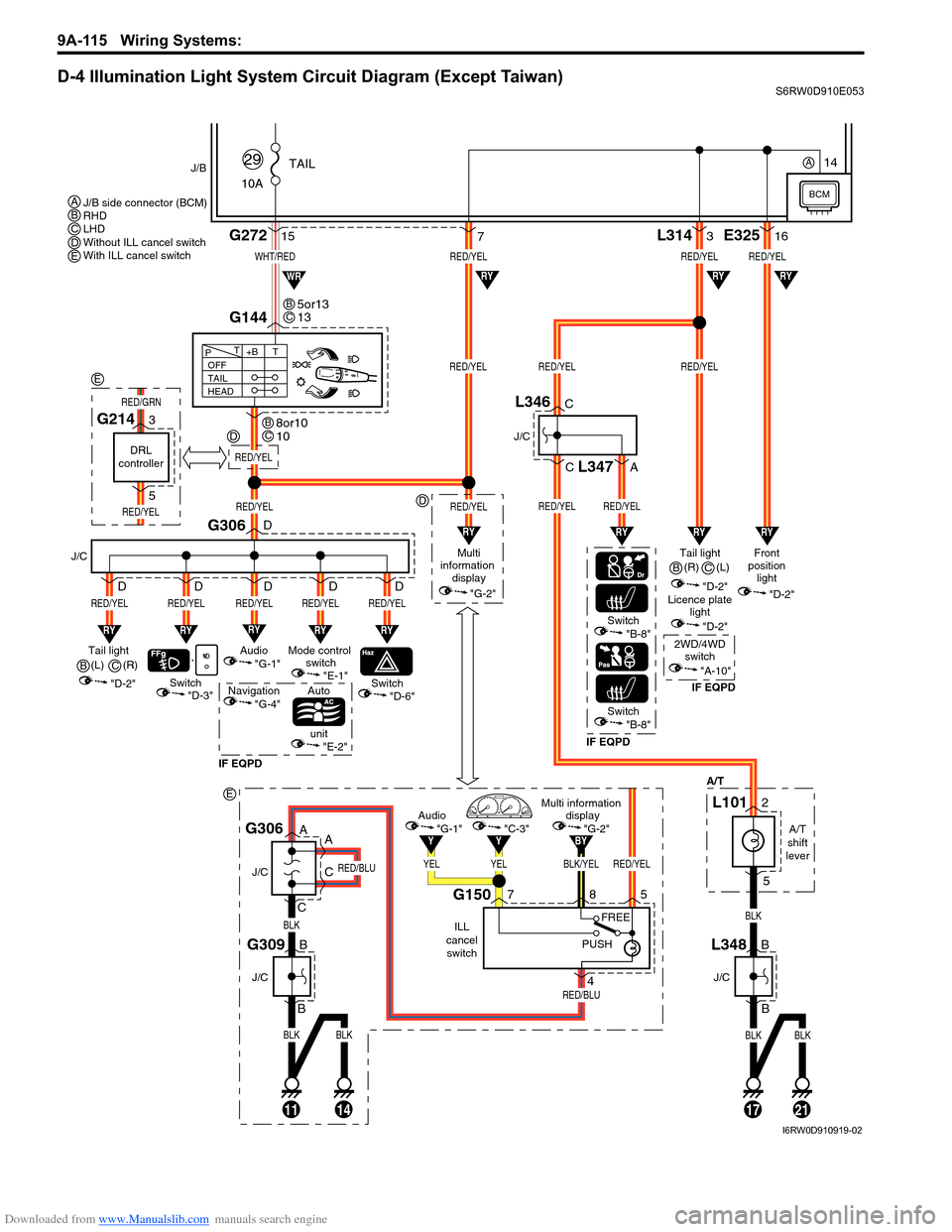
D-4 Illumination Light System Circuit Diagram (Except Taiwan)S6RW0D910E053
BLKBLK
BLK
RED/BLU
RED/BLU
11
J/C
J/C
B
B
14
G309
A
A
C
CG306
BLK/YELRED/YEL
BY
YELYEL
YY
Multi information
display
"G-2"Audio
"G-1""C-3"
ILL
cancel
switch
G150758
4
PUSHFREE
WHT/RED
10ATAIL
29J/B
15G272
G144
1721
RED/YELRED/YELRED/YEL
RED/YELRED/YEL
L3143
BLKBLK
BLK
"D-3"
A/T
RY
Switch
J/C
G306
RED/YEL
RY
RED/YEL
Switch
Auto
unit
IF EQPDIF EQPDIF EQPD
RY
RED/YEL
Mode control
switch
"E-1"Tail light
(L)
"D-2"
"E-2"
"D-6"Switch"B-8"
Switch"B-8"
OFF
TAIL
HEAD+BT T
P
7
RY
RED/YEL
Audio
"G-1"
Navigation
"G-4"
D
D
D D D
RY
RED/YEL
D
RED/YEL
Multi
information
display
"G-2"
RED/YEL
RYRYRY
RYRYWR
Tail light
"D-2"Front
position
light
"D-2"
Licence plate
light
"D-2"
2WD/4WD
switch
"A-10"
RED/YELRED/YEL
RED/YEL
E32516
RY
RY
J/C
B
BL348
J/C
C
C
A
L346
L347
A/T
shift
lever
L1012
5
5or13
13BC
8or10
10BC
J/B side connector (BCM)
RHD
LHD
Without ILL cancel switch
With ILL cancel switch ABCDE
B(R)
C
(R)
B(L)
C
BCM
14A
RED/YEL
D
D
E
DRL
controller
G2143
5
RED/YEL
RED/GRN
E
I6RW0D910919-02
Page 1283 of 1556
Downloaded from www.Manualslib.com manuals search engine Wiring Systems: 9A-116
D-4 Illumination Light System Circuit Diagram (Taiwan)S6RW0D910E025
BLU/WHT
RED/YEL
10ATAIL
36
J/B
12G272
10
G14413
131721
RED/YELRED/YEL
RED/YELRED/YELRED/YEL
L3143
BLKBLK
BLKBLK
"D-3"
A/T
RY
Switch
J/C
G306
RED/YEL
RY
RED/YEL
Switch
Auto
unit
RY
RED/YEL
Mode control
switch
"E-1"Tail light
(R)
"D-2"
"E-2"
"D-6"
OFF
TAIL
HEAD+BT T
P
187
RY
RED/YEL
Audio
"G-1"
D
D
D D D
RY
RED/YEL
D
RED/YEL
Multi
information
display
"G-2"
RED/YEL
RYRY
RYRY
RY
Tail light (L)
"D-2"Front
position
light
"D-2"
Licence plate
light
"D-2"
RED/YEL
RED/YEL
E32516
RY
RY
J/C
B
BL348
J/C
C
CL346
A/T
shift
lever
L1012
5
2 1
3
4
Tail light
relay
11
G05
G0412
BCM
I6RW0C910985-01
Page 1307 of 1556
Downloaded from www.Manualslib.com manuals search engine Wiring Systems: 9A-140
G-2 Multi Information Display / Accessory Socket System Circuit DiagramS6RW0D910E038
11
15AACC 2
24
J/C
G307
GY
Multi information display
J/B
BCM
13
BLK/ORN
2
BLK/ORN
15ADOME
37
15AACC
23
5
WHT/REDGRYYELBLU/WHT
G25314 3
WHT/REDYEL
RED/YEL
7
G309
J/C
J/B
5G272 G27112L314
WHT/BLKBLU/WHTWHT/BLK
BLKBLK
G251
ACC
Socket
2
1
1114
Rear
ACC
Socket
BLK
C
C
A
A
J/C
G308B
BC
C
G04
YEL/REDYEL/BLK
YEL/REDYEL/BLK
1E37
2
E04
G05
Ambient
temperature
sensor
Without ILL
cancel switch"D-4"
RY
BLK/YEL
ILL cancel
switch
With ILL
cancel switch"D-4"
BY
L2962
1
20
Except Taiwan
Taiwan AB
B
A
B
5
E381
G33334
11
5
AB8
16AB
10
24AB8
21AB
I6RW0D910925-01
Page 1332 of 1556

Downloaded from www.Manualslib.com manuals search engine 9B-13 Lighting Systems:
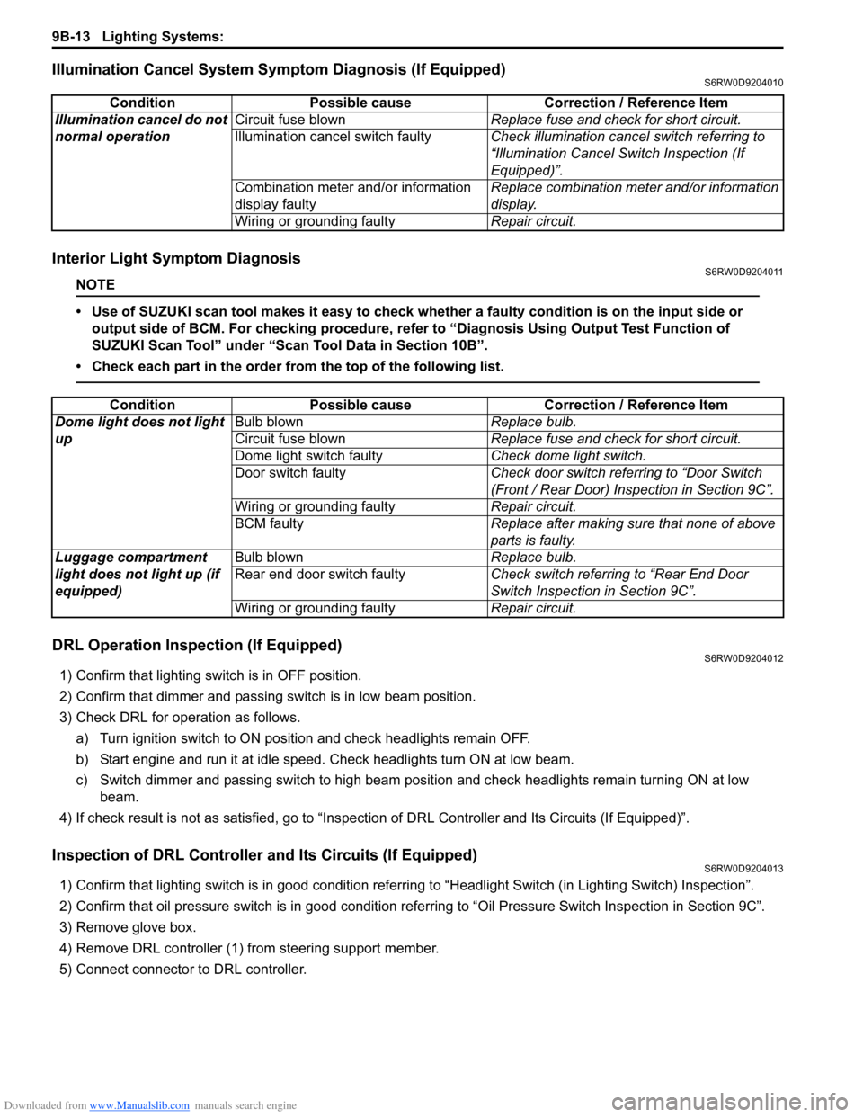
Illumination Cancel System Symptom Diagnosis (If Equipped)S6RW0D9204010
Interior Light Symptom DiagnosisS6RW0D9204011
NOTE
• Use of SUZUKI scan tool makes it easy to check whether a faulty condition is on the input side or
output side of BCM. For checking procedure, refer to “Diagnosis Using Output Test Function of
SUZUKI Scan Tool” under “Scan Tool Data in Section 10B”.
• Check each part in the order from the top of the following list.
DRL Operation Inspection (If Equipped)S6RW0D9204012
1) Confirm that lighting switch is in OFF position.
2) Confirm that dimmer and passing switch is in low beam position.
3) Check DRL for operation as follows.
a) Turn ignition switch to ON position and check headlights remain OFF.
b) Start engine and run it at idle speed. Check headlights turn ON at low beam.
c) Switch dimmer and passing switch to high beam position and check headlights remain turning ON at low
beam.
4) If check result is not as satisfied, go to “Inspection of DRL Controller and Its Circuits (If Equipped)”.
Inspection of DRL Controller and Its Circuits (If Equipped)S6RW0D9204013
1) Confirm that lighting switch is in good condition referring to “Headlight Switch (in Lighting Switch) Inspection”.
2) Confirm that oil pressure switch is in good condition referring to “Oil Pressure Switch Inspection in Section 9C”.
3) Remove glove box.
4) Remove DRL controller (1) from steering support member.
5) Connect connector to DRL controller.Condition Possible cause Correction / Reference Item
Illumination cancel do not
normal operationCircuit fuse blownReplace fuse and check for short circuit.
Illumination cancel switch faultyCheck illumination cancel switch referring to
“Illumination Cancel Switch Inspection (If
Equipped)”.
Combination meter and/or information
display faultyReplace combination meter and/or information
display.
Wiring or grounding faultyRepair circuit.
Condition Possible cause Correction / Reference Item
Dome light does not light
upBulb blownReplace bulb.
Circuit fuse blownReplace fuse and check for short circuit.
Dome light switch faultyCheck dome light switch.
Door switch faultyCheck door switch referring to “Door Switch
(Front / Rear Door) Inspection in Section 9C”.
Wiring or grounding faultyRepair circuit.
BCM faultyReplace after making sure that none of above
parts is faulty.
Luggage compartment
light does not light up (if
equipped)Bulb blownReplace bulb.
Rear end door switch faultyCheck switch referring to “Rear End Door
Switch Inspection in Section 9C”.
Wiring or grounding faultyRepair circuit.
Page 1362 of 1556

Downloaded from www.Manualslib.com manuals search engine 9C-10 Instrumentation / Driver Info. / Horn:
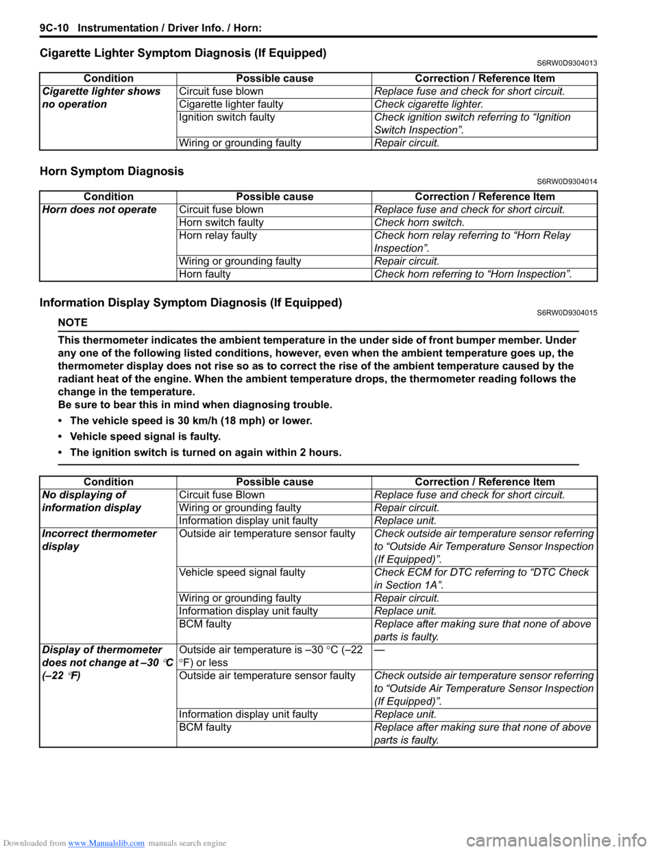
Cigarette Lighter Symptom Diagnosis (If Equipped)S6RW0D9304013
Horn Symptom DiagnosisS6RW0D9304014
Information Display Symptom Diagnosis (If Equipped)S6RW0D9304015
NOTE
This thermometer indicates the ambient temperature in the under side of front bumper member. Under
any one of the following listed conditions, however, even when the ambient temperature goes up, the
thermometer display does not rise so as to correct the rise of the ambient temperature caused by the
radiant heat of the engine. When the ambient temperature drops, the thermometer reading follows the
change in the temperature.
Be sure to bear this in mind when diagnosing trouble.
• The vehicle speed is 30 km/h (18 mph) or lower.
• Vehicle speed signal is faulty.
• The ignition switch is turned on again within 2 hours.
Condition Possible cause Correction / Reference Item
Cigarette lighter shows
no operationCircuit fuse blownReplace fuse and check for short circuit.
Cigarette lighter faultyCheck cigarette lighter.
Ignition switch faultyCheck ignition switch referring to “Ignition
Switch Inspection”.
Wiring or grounding faultyRepair circuit.
Condition Possible cause Correction / Reference Item
Horn does not operateCircuit fuse blownReplace fuse and check for short circuit.
Horn switch faultyCheck horn switch.
Horn relay faultyCheck horn relay referring to “Horn Relay
Inspection”.
Wiring or grounding faultyRepair circuit.
Horn faultyCheck horn referring to “Horn Inspection”.
Condition Possible cause Correction / Reference Item
No displaying of
information displayCircuit fuse BlownReplace fuse and check for short circuit.
Wiring or grounding faultyRepair circuit.
Information display unit faultyReplace unit.
Incorrect thermometer
displayOutside air temperature sensor faultyCheck outside air temperature sensor referring
to “Outside Air Temperature Sensor Inspection
(If Equipped)”.
Vehicle speed signal faultyCheck ECM for DTC referring to “DTC Check
in Section 1A”.
Wiring or grounding faultyRepair circuit.
Information display unit faultyReplace unit.
BCM faultyReplace after making sure that none of above
parts is faulty.
Display of thermometer
does not change at –30
°C
(–22
°F)Outside air temperature is –30 °C (–22
°F) or less—
Outside air temperature sensor faultyCheck outside air temperature sensor referring
to “Outside Air Temperature Sensor Inspection
(If Equipped)”.
Information display unit faultyReplace unit.
BCM faultyReplace after making sure that none of above
parts is faulty.