2006 SUZUKI SX4 check engine
[x] Cancel search: check enginePage 1062 of 1556
Downloaded from www.Manualslib.com manuals search engine 8B-23 Air Bag System:
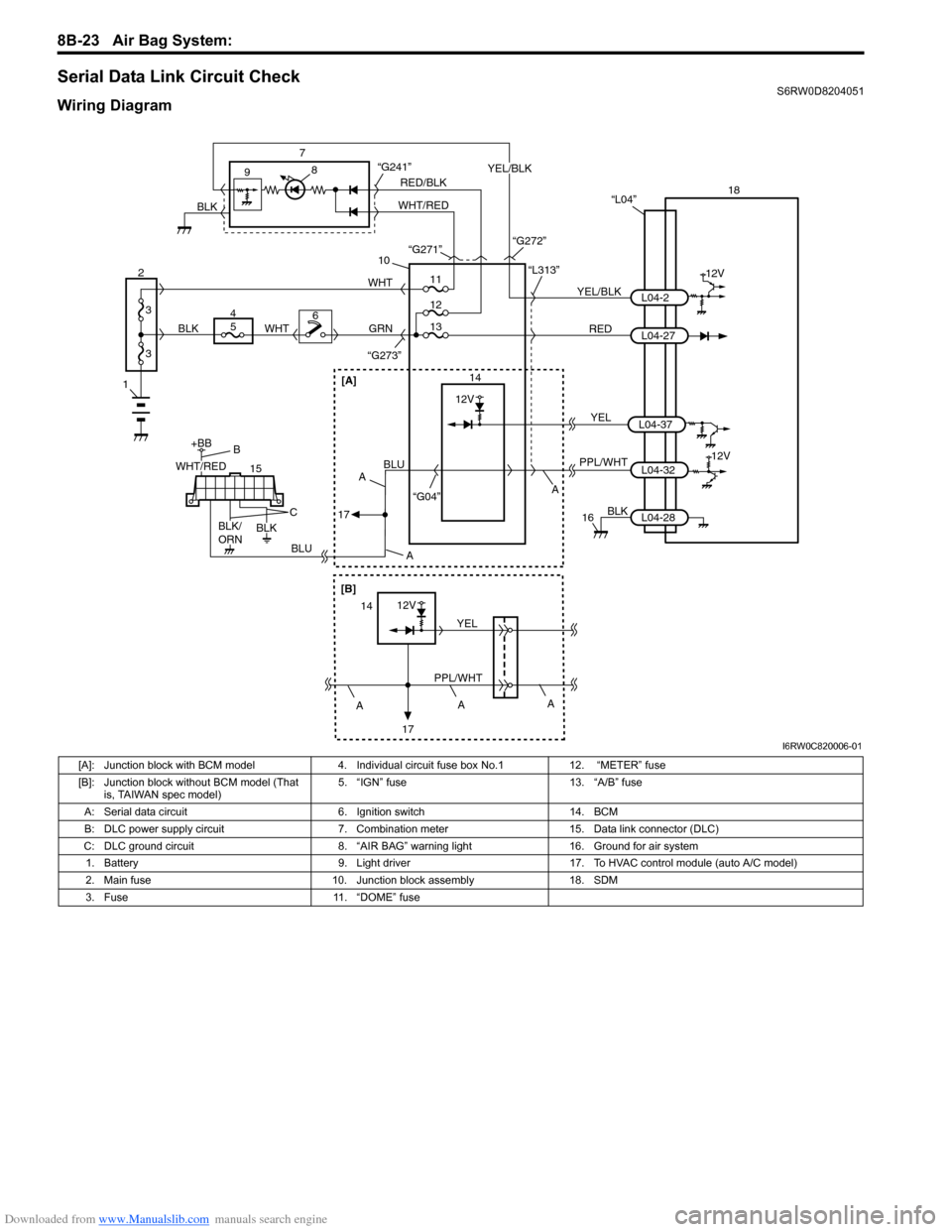
Serial Data Link Circuit CheckS6RW0D8204051
Wiring Diagram
1
2
3
3
18
12V
RED 7
14 9
10
“L313”
“G273”
YEL/BLKL04-2
L04-27 “L04”
PPL/WHT
“G04”L04-3212V
8
GRN
15
+BB
56WHTWHT
4
BLUBLU
BLK
16
11
12
“G241”
13
BLK
L04-28
RED/BLK
WHT/REDYEL/BLK
BLK“G271”
“G272”
WHT/RED
BLK/
ORNBLK
B
C
A A
A
17
[A]
A
[B]
12V
PPL/WHTYEL14
17A
A
YELL04-37
12V
I6RW0C820006-01
[A]: Junction block with BCM model 4. Individual circuit fuse box No.1 12. “METER” fuse
[B]: Junction block without BCM model (That
is, TAIWAN spec model)5. “IGN” fuse 13. “A/B” fuse
A: Serial data circuit 6. Ignition switch 14. BCM
B: DLC power supply circuit 7. Combination meter 15. Data link connector (DLC)
C: DLC ground circuit 8. “AIR BAG” warning light 16. Ground for air system
1. Battery 9. Light driver 17. To HVAC control module (auto A/C model)
2. Main fuse 10. Junction block assembly 18. SDM
3. Fuse 11. “DOME” fuse
Page 1063 of 1556
Downloaded from www.Manualslib.com manuals search engine Air Bag System: 8B-24
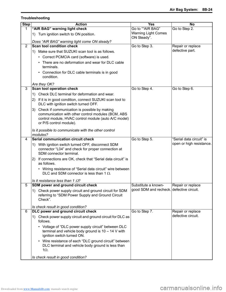
Troubleshooting
Step Action Yes No
1“AIR BAG” warning light check
1) Turn ignition switch to ON position.
Does “AIR BAG” warning light come ON steady?Go to ““AIR BAG”
Warning Light Comes
ON Steady”.Go to Step 2.
2Scan tool condition check
1) Make sure that SUZUKI scan tool is as follows.
• Correct PCMCIA card (software) is used.
• There are no deformation and wear for DLC cable
terminals.
• Connection for DLC cable terminals is in good
condition.
Are they OK?Go to Step 3. Repair or replace
defective part.
3Scan tool operation check
1) Check DLC terminal for deformation and wear.
2) If it is in good condition, connect SUZUKI scan tool to
DLC with ignition switch turned OFF.
3) Check if communication is possible by making
communication with other control modules (BCM, ABS
control module, HVAC control module (auto A/C model)
or P/S control module).
Is it possible to communicate with the other control
modules?Go to Step 4. Go to Step 6.
4Serial communication circuit check
1) With ignition switch turned OFF, disconnect SDM
connector “L04” and check for proper connection at
SDM connector terminal.
2) If connections are OK, check that “Serial data circuit” is
as follows.
• Wiring resistance of “Serial data circuit” wire between
DLC and SDM connector is less than 1 Ω.
Is it resistance less than 1
Ω?Go to Step 5. “Serial data circuit” is
open or high resistance.
5SDM power and ground circuit check
1) Check power supply circuit and ground circuit for SDM
referring to “SDM Power Supply and Ground Circuit
Check”.
Is check result in good condition?Substitute a known-
good SDM and recheck.Repair or replace
defective circuit.
6DLC power and ground circuit check
1) Check power supply circuit and ground circuit for DLC as
follows.
• Voltage of “DLC power supply circuit” between DLC
terminal and vehicle body ground is 10 – 14 V with
ignition switch turned ON.
• Wire resistance of each “DLC ground circuit” between
DLC terminal and vehicle body ground is less than
1Ω.
Is check result in good condition?Go to Step 7. Repair or replace
defective circuit.
Page 1064 of 1556
Downloaded from www.Manualslib.com manuals search engine 8B-25 Air Bag System:
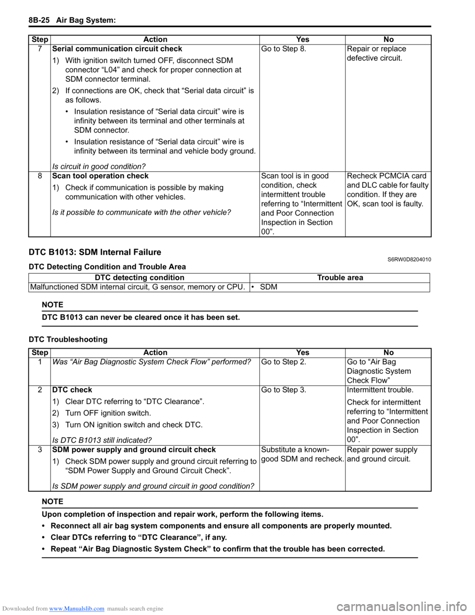
DTC B1013: SDM Internal FailureS6RW0D8204010
DTC Detecting Condition and Trouble Area
NOTE
DTC B1013 can never be cleared once it has been set.
DTC Troubleshooting
NOTE
Upon completion of inspection and repair work, perform the following items.
• Reconnect all air bag system components and ensure all components are properly mounted.
• Clear DTCs referring to “DTC Clearance”, if any.
• Repeat “Air Bag Diagnostic System Check” to confirm that the trouble has been corrected.
7Serial communication circuit check
1) With ignition switch turned OFF, disconnect SDM
connector “L04” and check for proper connection at
SDM connector terminal.
2) If connections are OK, check that “Serial data circuit” is
as follows.
• Insulation resistance of “Serial data circuit” wire is
infinity between its terminal and other terminals at
SDM connector.
• Insulation resistance of “Serial data circuit” wire is
infinity between its terminal and vehicle body ground.
Is circuit in good condition?Go to Step 8. Repair or replace
defective circuit.
8Scan tool operation check
1) Check if communication is possible by making
communication with other vehicles.
Is it possible to communicate with the other vehicle?Scan tool is in good
condition, check
intermittent trouble
referring to “Intermittent
and Poor Connection
Inspection in Section
00”.Recheck PCMCIA card
and DLC cable for faulty
condition. If they are
OK, scan tool is faulty. Step Action Yes No
DTC detecting condition Trouble area
Malfunctioned SDM internal circuit, G sensor, memory or CPU. • SDM
Step Action Yes No
1Was “Air Bag Diagnostic System Check Flow” performed?Go to Step 2. Go to “Air Bag
Diagnostic System
Check Flow”
2DTC check
1) Clear DTC referring to “DTC Clearance”.
2) Turn OFF ignition switch.
3) Turn ON ignition switch and check DTC.
Is DTC B1013 still indicated?Go to Step 3. Intermittent trouble.
Check for intermittent
referring to “Intermittent
and Poor Connection
Inspection in Section
00”.
3SDM power supply and ground circuit check
1) Check SDM power supply and ground circuit referring to
“SDM Power Supply and Ground Circuit Check”.
Is SDM power supply and ground circuit in good condition?Substitute a known-
good SDM and recheck.Repair power supply
and ground circuit.
Page 1065 of 1556
Downloaded from www.Manualslib.com manuals search engine Air Bag System: 8B-26
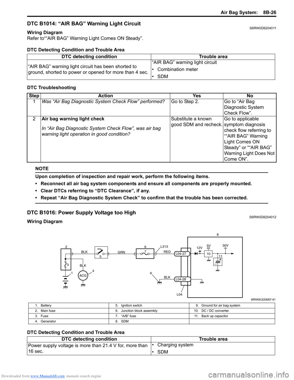
DTC B1014: “AIR BAG” Warning Light CircuitS6RW0D8204011
Wiring Diagram
Refer to““AIR BAG” Warning Light Comes ON Steady”.
DTC Detecting Condition and Trouble Area
DTC Troubleshooting
NOTE
Upon completion of inspection and repair work, perform the following items.
• Reconnect all air bag system components and ensure all components are properly mounted.
• Clear DTCs referring to “DTC Clearance”, if any.
• Repeat “Air Bag Diagnostic System Check” to confirm that the trouble has been corrected.
DTC B1016: Power Supply Voltage too HighS6RW0D8204012
Wiring Diagram
DTC Detecting Condition and Trouble AreaDTC detecting condition Trouble area
“AIR BAG” warning light circuit has been shorted to
ground, shorted to power or opened for more than 4 sec.“AIR BAG” warning light circuit
• Combination meter
•SDM
Step Action Yes No
1Was “Air Bag Diagnostic System Check Flow” performed?Go to Step 2. Go to “Air Bag
Diagnostic System
Check Flow”.
2Air bag warning light check
In “Air Bag Diagnostic System Check Flow”, was air bag
warning light operation in good condition?Substitute a known
good SDM and recheck.Go to applicable
symptom diagnosis
check flow referring to
““AIR BAG” Warning
Light Comes ON
Steady” or ““AIR BAG”
Warning Light Does Not
Come ON”.
BLK
L04
7
RED
GRN L313
98
L04-28
L04-27
1
2
3
BLK
45 BLK6
ACG
10
12V5V30V
11
I6RW0C820007-01
1. Battery 5. Ignition switch 9. Ground for air bag system
2. Main fuse 6. Junction block assembly 10. DC / DC converter
3. Fuse 7. “A/B” fuse 11. Back up capacitor
4. Generator 8. SDM
DTC detecting condition Trouble area
Power supply voltage is more than 21.4 V for, more than
16 sec.• Charging system
•SDM
Page 1066 of 1556
Downloaded from www.Manualslib.com manuals search engine 8B-27 Air Bag System:
DTC Troubleshooting
NOTE
Upon completion of inspection and repair work, perform the following items.
• Reconnect all air bag system components and ensure all components are properly mounted.
• Clear DTCs referring to “DTC Clearance”, if any.
• Repeat “Air Bag Diagnostic System Check” to confirm that the trouble has been corrected.
DTC B1017: Power Supply Voltage too LowS6RW0D8204013
Wiring Diagram
Refer to “DTC B1016: Power Supply Voltage too High”.
DTC Detecting Condition and Trouble AreaStep Action Yes No
1Was “Air Bag Diagnostic System Check Flow” performed?Go to Step 2. Go to “Air Bag
Diagnostic System
Check Flow”.
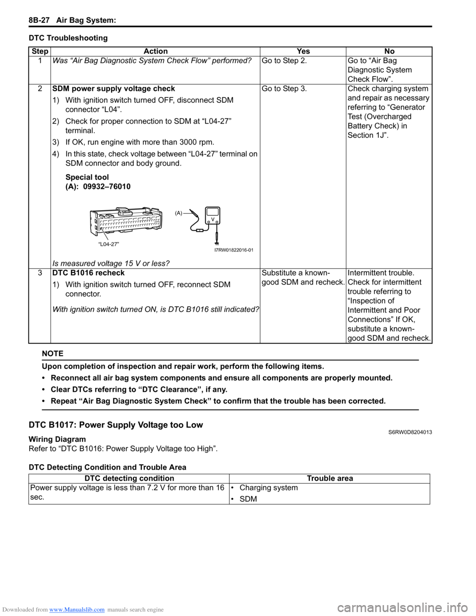
2SDM power supply voltage check
1) With ignition switch turned OFF, disconnect SDM
connector “L04”.
2) Check for proper connection to SDM at “L04-27”
terminal.
3) If OK, run engine with more than 3000 rpm.
4) In this state, check voltage between “L04-27” terminal on
SDM connector and body ground.
Special tool
(A): 09932–76010
Is measured voltage 15 V or less?Go to Step 3. Check charging system
and repair as necessary
referring to “Generator
Test (Overcharged
Battery Check) in
Section 1J”.
3DTC B1016 recheck
1) With ignition switch turned OFF, reconnect SDM
connector.
With ignition switch turned ON, is DTC B1016 still indicated?Substitute a known-
good SDM and recheck.Intermittent trouble.
Check for intermittent
trouble referring to
“Inspection of
Intermittent and Poor
Connections” If OK,
substitute a known-
good SDM and recheck.
“L04-27”
(A)
I7RW01822016-01
DTC detecting condition Trouble area
Power supply voltage is less than 7.2 V for more than 16
sec.• Charging system
•SDM
Page 1067 of 1556
Downloaded from www.Manualslib.com manuals search engine Air Bag System: 8B-28
DTC Troubleshooting
NOTE
Upon completion of inspection and repair work, perform the following items.
• Reconnect all air bag system components and ensure all components are properly mounted.
• Clear DTCs referring to “DTC Clearance”, if any.
• Repeat “Air Bag Diagnostic System Check” to confirm that the trouble has been corrected.
DTC B1021: Front Air Bag Deployment RecordS6RW0D8204014
DTC Detecting Condition and Trouble Area
NOTE
DTC B1201 can never be cleared once it has been set.
DTC TroubleshootingStep Action Yes No
1Was “Air Bag Diagnostic System Check Flow” performed?Go to Step 2. Go to “Air Bag
Diagnostic System
Check Flow”.
2SDM power supply and ground circuit check
1) Check SDM power supply and ground circuit referring to
“SDM Power Supply and Ground Circuit Check”.
Is SDM power supply and ground circuit in good condition?Go to Step 3. Repair defective wire
circuit.
3DTC B1017 recheck
1) With ignition switch turned OFF, reconnect SDM
connector.
With ignition switch ON, does DTC B1017 exist?Substitute a known-
good SDM and recheck.Intermittent trouble.
Check for intermittent
trouble referring to
“Inspection of
Intermittent and Poor
Connections” If OK,
substitute a known-
good SDM and recheck.
DTC detecting condition Trouble area
Deployment of front air bag has been recorded in SDM.If this DTC has been recorded even though air bag has
not been deployed
•SDM
• Driver and/or Passenger air bag module
• Those initiator circuit.
Step Action Yes No
1Was “Air Bag Diagnostic System Check Flow” performed?Go to Step 2. Go to “Air Bag
Diagnostic System
Check Flow”.
2Front air bag deployment check
1) Turn OFF ignition switch.
2) Check that DTC B1021 has been set although air bag
has not been deployed.
Has air bag deployed? Inspect and replace
components according
to “Repair and
Inspection Required
after Accident”.Go to Step 3.
3Front impact sign check
1) Inspect front of vehicle and undercarriage for signs of
impact.
Are there any signs of impact?Inspect and replace
components according
to “Repair and
Inspection Required
after Accident”.Replace SDM.
Page 1068 of 1556
Downloaded from www.Manualslib.com manuals search engine 8B-29 Air Bag System:
NOTE
Upon completion of inspection and repair work, perform the following items.
• Reconnect all air bag system components and ensure all components are properly mounted.
• Repeat “Air Bag Diagnostic System Check” to confirm that the trouble has been corrected.
• Clear DTCs of BCM referring to “DTC Clearance in Section 10B”.
• Clear DTC B1157 (air bag deployed) of BCM referring to “DTC Clearance in Section 10B”, if any.
DTC B1024 / B1025: Side Air-Bag Deployment RecordS6RW0D8204052
DTC B1024: Driver Side Air-Bag Deployment Record
DTC B1025: Passenger Side Air-Bag Deployment Record
DTC Detecting Condition and Trouble Area
DTC Troubleshooting
NOTE
Upon completion of inspection and repair work, perform the following items.
• Reconnect all air bag system components and ensure all components are properly mounted.
• Repeat “Air Bag Diagnostic System Check” to confirm that the trouble has been corrected.
• Clear DTC B1157 (air bag deployed) of BCM referring to “DTC Clearance in Section 10B”, if any.
DTC B1026: Seat Belt Pretensioner Activation RecordS6RW0D8204016
DTC Detecting Condition and Trouble AreaDTC detecting condition Trouble area
DTC B1024:
Deployment of driver side-air bag has been recorded in
SDM.
DTC B1025:
Deployment of passenger side-air bag has been recorded
in SDM.If this DTC has been recorded even though side-air bag
has not been deployed
•SDM
• Driver (passenger) side-air bag module
• Its initiator circuit
Step Action Yes No
1Was “Air Bag Diagnostic System Check Flow” performed?Go to Step 2. Go to “Air Bag
Diagnostic System
Check Flow”.
2Side-air bag deployment check
1) Turn OFF ignition switch.
2) Check that DTC B1024 or B1025 has been set although
side-air bag has not been deployed.
Has air bag deployed?Inspect and replace
components according
to “Repair and
Inspection Required
after Accident”.Go to Step 3.
3Side impact sign (driver / passenger) check
1) Inspect side of vehicle and undercarriage for signs of
impact.
Are there any signs of impact?Inspect and replace
components according
to “Repair and
Inspection Required
after Accident”.Replace SDM.
DTC detecting condition Trouble area
Activation of seat belt pretensioner has been recorded in
SDM.If this DTC has been recorded even though pretensioner
has not been activated
•SDM
• Driver and/or Passenger seat belt pretensioner
• Those initiator circuit
Page 1069 of 1556
Downloaded from www.Manualslib.com manuals search engine Air Bag System: 8B-30
DTC Troubleshooting
NOTE
Upon completion of inspection and repair work, perform the following items.
• Reconnect all air bag system components and ensure all components are properly mounted.
• Repeat “Air Bag Diagnostic System Check” to confirm that the trouble has been corrected.
• Clear DTC B1157 (air bag deployed) of BCM referring to “DTC Clearance in Section 10B”, if any.
DTC B1027: Number of Deployment Times Exceeded LimitS6RW0D8204017
DTC Detecting Condition and Trouble Area
NOTE
DTC B1027 can never be cleared once it has been set.
DTC Trouble shootingStep Action Yes No
1Was “Air Bag Diagnostic System Check Flow” performed?Go to Step 2. Go to “Air Bag
Diagnostic System
Check Flow”.
2Seat belt pretensioner activation check
1) Turn OFF ignition switch.
2) Check that DTC B1026 has been set although
pretensioner has not been activated.
Has pretensioner activated?Inspect and replace
components according
to “Repair and
Inspection Required
after Accident”.Go to Step 3.
3Front impact sign check
1) Inspect front of vehicle and undercarriage for signs of
impact.
Are there any signs of impact?Inspect and replace
components according
to “Repair and
Inspection Required
after Accident”.Replace SDM.
DTC detecting condition Trouble area
Deployment of air bag and/or activation of seat belt
pretensioner have been recorded in SDM 5 times or
more.If this DTC has been recorded even though air bag (front
and side) and pretensioner have not been deployed more
than 4 place.
• SDM (internal fault or reused SDM)
• Each of deployment and activation module
• Those initiator circuit
Step Action Yes No
1Was “Air Bag Diagnostic System Check Flow” performed?Go to Step 2. Go to “Air Bag
Diagnostic System
Check Flow”.
2Air bag deployment check
1) Turn OFF ignition switch.
2) Check that DTC B1027 has been set although air bag
(front and side) and pretensioner has not been
deployed.
Have air bag and pretensioner deployed more than 4 place?Inspect and replace
components according
to “Repair and
Inspection Required
after Accident”.Go to Step 3.
3Impact sign check
1) Inspect front, side of vehicle and undercarriage for signs
of impact.
Are there any signs of impact?Inspect and replace
components according
to “Repair and
Inspection Required
after Accident”.Replace SDM.