2006 SUZUKI SX4 fuse box diagram
[x] Cancel search: fuse box diagramPage 1106 of 1556
Downloaded from www.Manualslib.com manuals search engine 8B-67 Air Bag System:
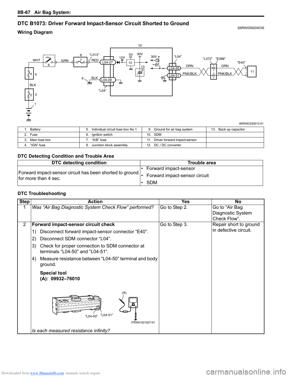
DTC B1073: Driver Forward Impact-Sensor Circuit Shorted to GroundS6RW0D8204036
Wiring Diagram
DTC Detecting Condition and Trouble Area
DTC Troubleshooting
10
“L04”
“L372” “E388”
“E40”
ORN
PNK/BLKORN
PNK/BLKL04-50
L04-5111
30V
“L04”
BLK
L04-28
6 8
7
RED
GRN“L313”L04-27
9
1
2 BLKWHT3
4
5
12
12V5V30V
13
I6RW0C820012-01
1. Battery 5. Individual circuit fuse box No.1 9. Ground for air bag system 13. Back up capacitor
2. Fuse 6. Ignition switch 10. SDM
3. Main fuse box 7. “A/B” fuse 11. Driver forward impact-sensor
4. “IGN” fuse 8. Junction block assembly 12. DC / DC converter
DTC detecting condition Trouble area
Forward impact-sensor circuit has been shorted to ground
for more than 4 sec.• Forward impact-sensor
• Forward impact-sensor circuit
•SDM
Step Action Yes No
1Was “Air Bag Diagnostic System Check Flow” performed?Go to Step 2. Go to “Air Bag
Diagnostic System
Check Flow”.
2Forward impact-sensor circuit check
1) Disconnect forward impact-sensor connector “E40”.
2) Disconnect SDM connector “L04”.
3) Check for proper connection to SDM connector at
terminals “L04-50” and “L04-51”.
4) Measure resistance between “L04-50” terminal and body
ground.
Special tool
(A): 09932–76010
Is each measured resistance infinity?Go to Step 3. Repair short to ground
in defective circuit.
“L04-50”“L04-51”
(A)
I7RW01821027-01
Page 1110 of 1556
Downloaded from www.Manualslib.com manuals search engine 8B-71 Air Bag System:
DTC Troubleshooting
NOTE
Upon completion of inspection and repair work, perform the following items.
• Reconnect all air bag system components and ensure all components are properly mounted.
• Clear DTCs referring to “DTC Clearance”, if any.
• Repeat “Air Bag Diagnostic System Check” to confirm that the trouble has been corrected.
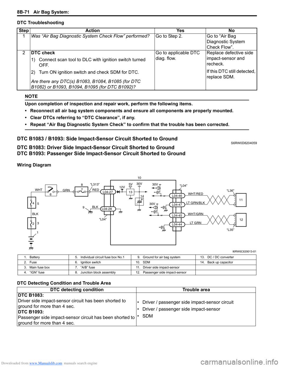
DTC B1083 / B1093: Side Impact-Sensor Circuit Shorted to GroundS6RW0D8204059
DTC B1083: Driver Side Impact-Sensor Circuit Shorted to Ground
DTC B1093: Passenger Side Impact-Sensor Circuit Shorted to Ground
Wiring Diagram
DTC Detecting Condition and Trouble AreaStep Action Yes No
1Was “Air Bag Diagnostic System Check Flow” performed?Go to Step 2. Go to “Air Bag
Diagnostic System
Check Flow”.
2DTC check
1) Connect scan tool to DLC with ignition switch turned
OFF.
2) Turn ON ignition switch and check SDM for DTC.
Are there any DTC(s) B1083, B1084, B1085 (for DTC
B1082) or B1093, B1094, B1095 (for DTC B1092)?Go to applicable DTC
diag. flow.Replace defective side
impact-sensor and
recheck.
If this DTC still detected,
replace SDM.
10
“L04”30V
30VL04-47 L04-46WHT/RED
LT GRN/BLK“L36”
11
L04-44 L04-45WHT/GRN
LT GRN
“L35”12
“L04”
BLK
L04-28
6 8
7
RED
GRN“L313”L04-27
9
1
2 BLKWHT3
4
5
13
12V5V30V
14
I6RW0C820013-01
1. Battery 5. Individual circuit fuse box No.1 9. Ground for air bag system 13. DC / DC converter
2. Fuse 6. Ignition switch 10. SDM 14. Back up capacitor
3. Main fuse box 7. “A/B” fuse 11. Driver side impact-sensor
4. “IGN” fuse 8. Junction block assembly 12. Passenger side impact-sensor
DTC detecting condition Trouble area
DTC B1083:
Driver side impact-sensor circuit has been shorted to
ground for more than 4 sec.
DTC B1093:
Passenger side impact-sensor circuit has been shorted to
ground for more than 4 sec.• Driver / passenger side impact-sensor circuit
• Driver / passenger side impact-sensor
•SDM
Page 1114 of 1556
Downloaded from www.Manualslib.com manuals search engine 8B-75 Air Bag System:
NOTE
Upon completion of inspection and repair work, perform the following items.
• Reconnect all air bag system components and ensure all components are properly mounted.
• Clear DTCs referring to “DTC Clearance”, if any.
• Repeat “Air Bag Diagnostic System Check” to confirm that the trouble has been corrected.
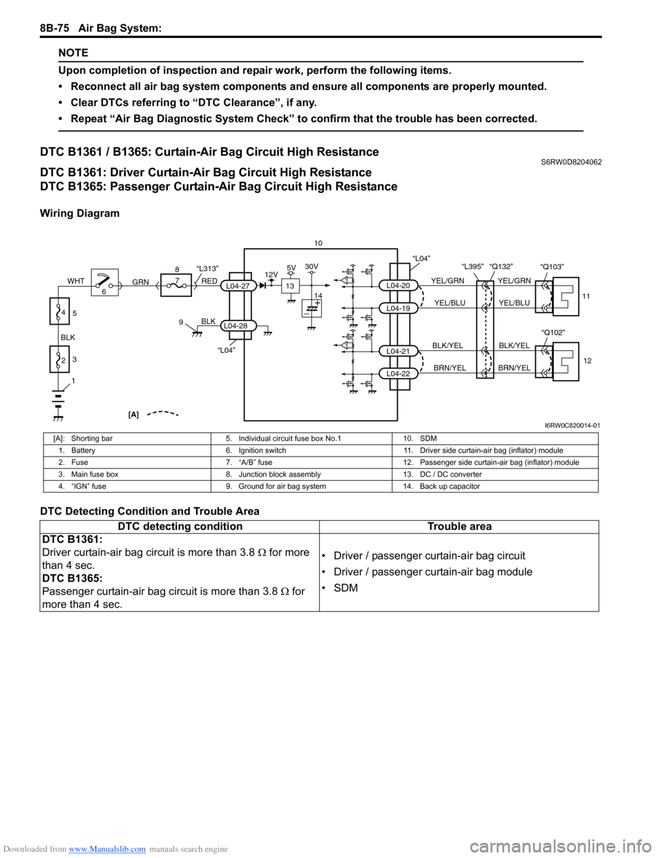
DTC B1361 / B1365: Curtain-Air Bag Circuit High ResistanceS6RW0D8204062
DTC B1361: Driver Curtain-Air Bag Circuit High Resistance
DTC B1365: Passenger Curtain-Air Bag Circuit High Resistance
Wiring Diagram
DTC Detecting Condition and Trouble Area
10
L04-20
L04-19
L04-21
L04-22
YEL/GRN
YEL/BLU
BLK/YEL
BRN/YELYEL/GRN
YEL/BLU
BLK/YEL
BRN/YEL “L395” “Q132”
11
12
“L04”
“Q102” “Q103”
“L04”
BLK
L04-28
6 8
7
RED
GRN“L313”L04-27
9
1
2 BLKWHT3
4
5
[A]
13
12V5V30V
14
I6RW0C820014-01
[A]: Shorting bar 5. Individual circuit fuse box No.1 10. SDM
1. Battery 6. Ignition switch 11. Driver side curtain-air bag (inflator) module
2. Fuse 7. “A/B” fuse 12. Passenger side curtain-air bag (inflator) module
3. Main fuse box 8. Junction block assembly 13. DC / DC converter
4. “IGN” fuse 9. Ground for air bag system 14. Back up capacitor
DTC detecting condition Trouble area
DTC B1361:
Driver curtain-air bag circuit is more than 3.8 Ω for more
than 4 sec.
DTC B1365:
Passenger curtain-air bag circuit is more than 3.8 Ω for
more than 4 sec.• Driver / passenger curtain-air bag circuit
• Driver / passenger curtain-air bag module
•SDM
Page 1124 of 1556
Downloaded from www.Manualslib.com manuals search engine 8B-85 Air Bag System:
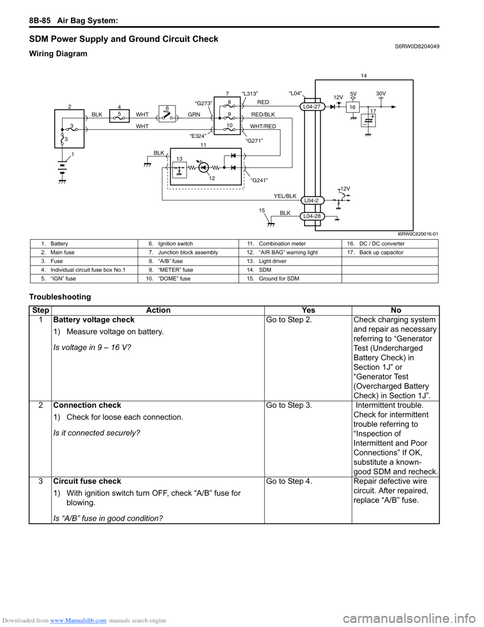
SDM Power Supply and Ground Circuit CheckS6RW0D8204049
Wiring Diagram
Troubleshooting
“L04”14
5
9RED
RED/BLK GRN
YEL/BLK
BLK
8 7
11
12
15
L04-2
L04-28
L04-27
“G241” “G271” “L313”
13
12V
6
1BLK
WHT WHT
WHT/RED 2
34
310 BLK
“G273”
“E324”16
12V5V30V
17
I6RW0C820016-01
1. Battery 6. Ignition switch 11. Combination meter 16. DC / DC converter
2. Main fuse 7. Junction block assembly 12. “AIR BAG” warning light 17. Back up capacitor
3. Fuse 8. “A/B” fuse 13. Light driver
4. Individual circuit fuse box No.1 9. “METER” fuse 14. SDM
5. “IGN” fuse 10. “DOME” fuse 15. Ground for SDM
Step Action Yes No
1Battery voltage check
1) Measure voltage on battery.
Is voltage in 9 – 16 V?Go to Step 2. Check charging system
and repair as necessary
referring to “Generator
Test (Undercharged
Battery Check) in
Section 1J” or
“Generator Test
(Overcharged Battery
Check) in Section 1J”.
2Connection check
1) Check for loose each connection.
Is it connected securely?Go to Step 3. Intermittent trouble.
Check for intermittent
trouble referring to
“Inspection of
Intermittent and Poor
Connections” If OK,
substitute a known-
good SDM and recheck.
3Circuit fuse check
1) With ignition switch turn OFF, check “A/B” fuse for
blowing.
Is “A/B” fuse in good condition?Go to Step 4. Repair defective wire
circuit. After repaired,
replace “A/B” fuse.
Page 1161 of 1556
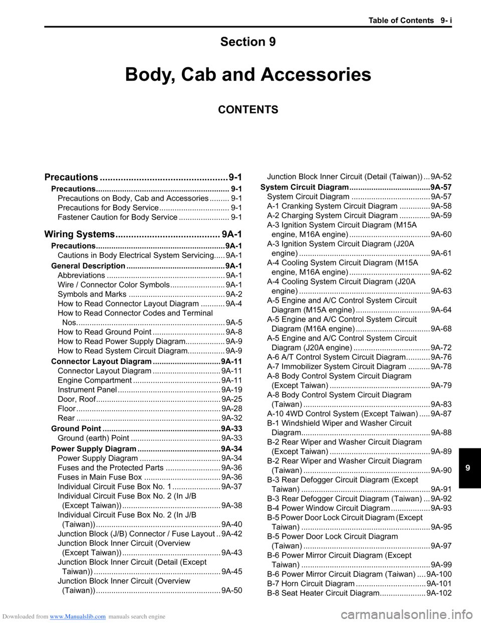
Downloaded from www.Manualslib.com manuals search engine Table of Contents 9- i
9
Section 9
CONTENTS
Body, Cab and Accessories
Precautions ................................................. 9-1
Precautions............................................................. 9-1
Precautions on Body, Cab and Accessories ......... 9-1
Precautions for Body Service ................................ 9-1
Fastener Caution for Body Service ....................... 9-1
Wiring Systems........................................ 9A-1
Precautions........................................................... 9A-1
Cautions in Body Electrical System Servicing..... 9A-1
General Description ............................................. 9A-1
Abbreviations ...................................................... 9A-1
Wire / Connector Color Symbols ......................... 9A-1
Symbols and Marks ............................................ 9A-2
How to Read Connector Layout Diagram ........... 9A-4
How to Read Connector Codes and Terminal
Nos.................................................................... 9A-5
How to Read Ground Point ................................. 9A-8
How to Read Power Supply Diagram.................. 9A-9
How to Read System Circuit Diagram................. 9A-9
Connector Layout Diagram ............................... 9A-11
Connector Layout Diagram ............................... 9A-11
Engine Compartment ........................................ 9A-11
Instrument Panel ............................................... 9A-19
Door, Roof......................................................... 9A-25
Floor .................................................................. 9A-28
Rear .................................................................. 9A-32
Ground Point ...................................................... 9A-33
Ground (earth) Point ......................................... 9A-33
Power Supply Diagram ...................................... 9A-34
Power Supply Diagram ..................................... 9A-34
Fuses and the Protected Parts ......................... 9A-36
Fuses in Main Fuse Box ................................... 9A-36
Individual Circuit Fuse Box No. 1 ...................... 9A-37
Individual Circuit Fuse Box No. 2 (In J/B
(Except Taiwan)) ............................................. 9A-38
Individual Circuit Fuse Box No. 2 (In J/B
(Taiwan)) ......................................................... 9A-40
Junction Block (J/B) Connector / Fuse Layout .. 9A-42
Junction Block Inner Circuit (Overview
(Except Taiwan)) ............................................. 9A-43
Junction Block Inner Circuit (Detail (Except
Taiwan)) .......................................................... 9A-45
Junction Block Inner Circuit (Overview
(Taiwan)) ......................................................... 9A-50Junction Block Inner Circuit (Detail (Taiwan)) ... 9A-52
System Circuit Diagram.....................................9A-57
System Circuit Diagram .................................... 9A-57
A-1 Cranking System Circuit Diagram .............. 9A-58
A-2 Charging System Circuit Diagram .............. 9A-59
A-3 Ignition System Circuit Diagram (M15A
engine, M16A engine) ..................................... 9A-60
A-3 Ignition System Circuit Diagram (J20A
engine) ............................................................ 9A-61
A-4 Cooling System Circuit Diagram (M15A
engine, M16A engine) ..................................... 9A-62
A-4 Cooling System Circuit Diagram (J20A
engine) ............................................................ 9A-63
A-5 Engine and A/C Control System Circuit
Diagram (M15A engine) .................................. 9A-64
A-5 Engine and A/C Control System Circuit
Diagram (M16A engine) .................................. 9A-68
A-5 Engine and A/C Control System Circuit
Diagram (J20A engine) ................................... 9A-72
A-6 A/T Control System Circuit Diagram........... 9A-76
A-7 Immobilizer System Circuit Diagram .......... 9A-78
A-8 Body Control System Circuit Diagram
(Except Taiwan) .............................................. 9A-79
A-8 Body Control System Circuit Diagram
(Taiwan) .......................................................... 9A-83
A-10 4WD Control System (Except Taiwan) ..... 9A-87
B-1 Windshield Wiper and Washer Circuit
Diagram........................................................... 9A-88
B-2 Rear Wiper and Washer Circuit Diagram
(Except Taiwan) .............................................. 9A-89
B-2 Rear Wiper and Washer Circuit Diagram
(Taiwan) .......................................................... 9A-90
B-3 Rear Defogger Circuit Diagram (Except
Taiwan) ........................................................... 9A-91
B-3 Rear Defogger Circuit Diagram (Taiwan) ... 9A-92
B-4 Power Window Circuit Diagram .................. 9A-93
B-5 Power Door Lock Circuit Diagram (Except
Taiwan) ........................................................... 9A-95
B-5 Power Door Lock Circuit Diagram
(Taiwan) .......................................................... 9A-97
B-6 Power Mirror Circuit Diagram (Except
Taiwan) ........................................................... 9A-99
B-6 Power Mirror Circuit Diagram (Taiwan) .... 9A-100
B-7 Horn Circuit Diagram ................................ 9A-101
B-8 Seat Heater Circuit Diagram..................... 9A-102
Page 1175 of 1556
Downloaded from www.Manualslib.com manuals search engine Wiring Systems: 9A-8
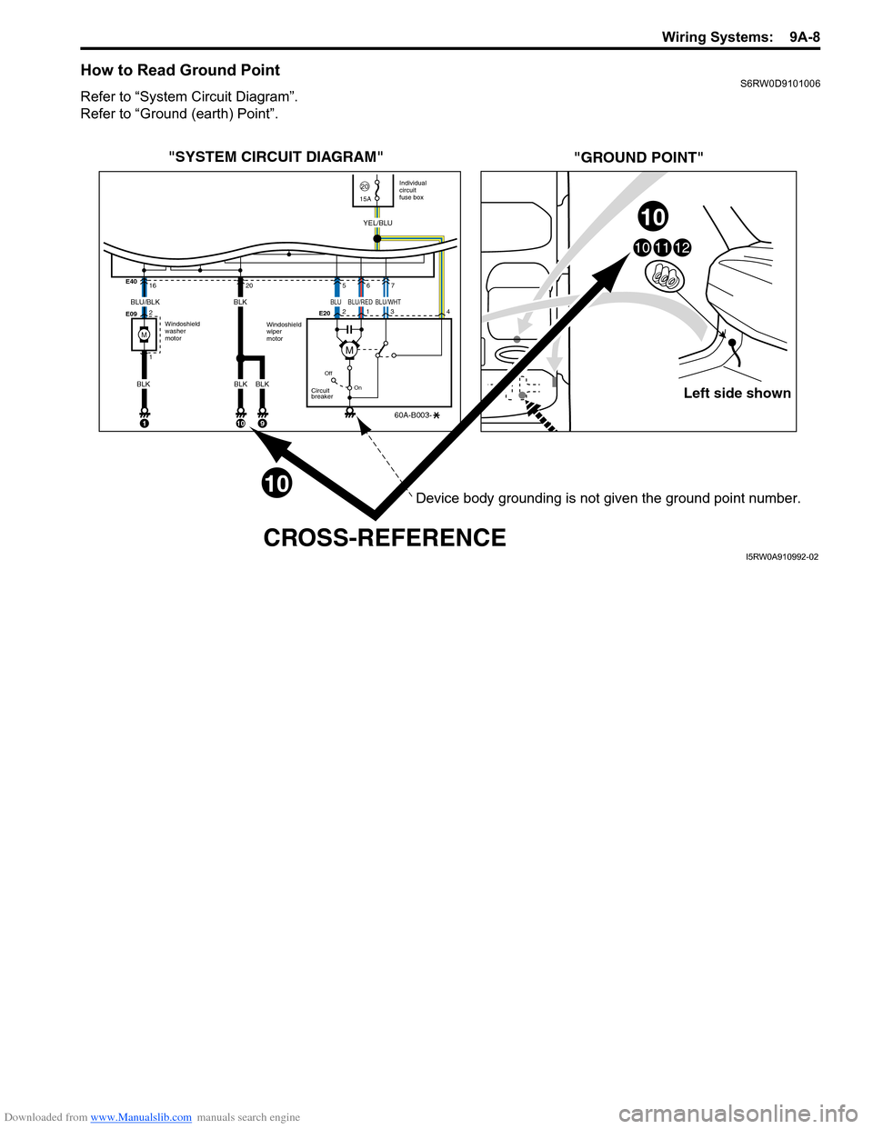
How to Read Ground PointS6RW0D9101006
Refer to “System Circuit Diagram”.
Refer to “Ground (earth) Point”.
Left side shown
101112
"SYSTEM CIRCUIT DIAGRAM"
"GROUND POINT"
CROSS-REFERENCE
Windoshield
washer
motorIndividual
circuit
fuse box
2015A
Windoshield
wiper
motor E40
E09E20 16
2
1
Off
On
Circuit
breaker
60A-B003-
YEL/BLU
1
205
2
134
67
BLU/BLK
BLK
10
BLK
BLK
9
10
10
BLK
M
BLUBLU/WHTBLU/RED
M
Device body grounding is not given the ground point number.
I5RW0A910992-02
Page 1176 of 1556
Downloaded from www.Manualslib.com manuals search engine 9A-9 Wiring Systems:
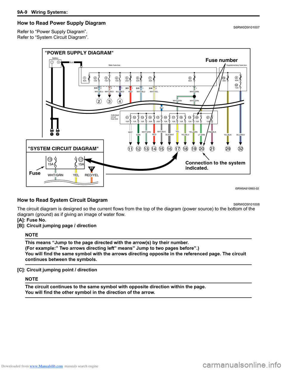
How to Read Power Supply DiagramS6RW0D9101007
Refer to “Power Supply Diagram”.
Refer to “System Circuit Diagram”.
How to Read System Circuit DiagramS6RW0D9101008
The circuit diagram is designed so the current flows from the top of the diagram (power source) to the bottom of the
diagram (ground) as if giving an image of water flow.
[A]: Fuse No.
[B]: Circuit jumping page / direction
NOTE
This means “Jump to the page directed with the arrow(s) by their number.
(For example:” Two arrows directing left” means” Jump to two pages before”.)
You will find the same symbol with the arrows directing opposite in the referenced page. The circuit
continues between the symbols.
[C]: Circuit jumping point / direction
NOTE
The circuit continues to the same symbol with opposite direction within the page.
You will find the other symbol in the direction of the arrow.
Connection to the system
indicated. "POWER SUPPLY DIAGRAM"
-+
1
Battery
80A
215A315A415A525A67850A 30A2930A3215A
960A
60A
BLK
YEL/BLKPNK/BLKLT GRNYEL/GRNYEL/BLUBLK/WHTWHT/BLKWHT/GRNREDGRNWHT
WHT/BLUWHT/REDWHT/BLUWHT/YELWHT/GRN
WHT/GRNWHT/GRN
BLU
BLU/REDRED
YELBLU/RED Individual
circuit
fuse box Main fuse boxSupplementary fuse box
11
11
243
121314151617181920212932
1213141516171819202115A 15A 15A 20A 20A 15A 15A 15A 15A 15A 15A E44321
B011E451E4021
FuseRED/YEL YEL WHT/GRN
15A
15A 1317
"SYSTEM CIRCUIT DIAGRAM"
Fuse number
12
RY
I5RW0A910993-02
Page 1201 of 1556
Downloaded from www.Manualslib.com manuals search engine Wiring Systems: 9A-34
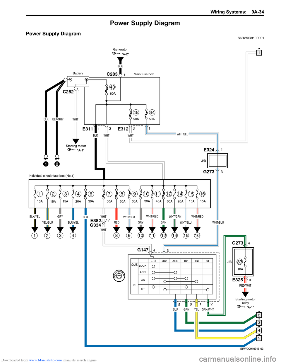
Power Supply Diagram
Power Supply DiagramS6RW0D910D001
G273
J/B
J/B
3
WHT/BLU
GRN/WHT
RED/WHT
4G1473
1
2
8
BLK
21
BLK/GRY
15A
15A15A
2314678
1E3112
WHT
1112141516
BLK/YELGRY
3
YEL/BLU
21
BLU/YEL
4
BLU
RED
WHT
WHT
WHT/RED
11
WHT/GRN
14
WHT/BLU
1516
WHT/RED
GRN
12
30A
9
WHT/BLU
9
30A
20A30A 50A40A
60A
20A15A
15A
BLK
2E3121
WHT/BLU
C282C28311
WHT
BLK
Main fuse box
Starting motor
"A-1"Generator
"A-2"
Battery
80A
50A 50A
4544
43
E3241
E32510
G2734
WHT
YEL
Individual circuit fuse box (No.1)
+B1
LOCK
ACC
ON
STACC IG1 IG2STOUT
IN
+B2
6
GRNBLU
5
Starting motor
relay
10
GRY
10
30A
E382
G33417
1
5
4
3
2
"A-1"
33
10A
I6RW0C910918-03