2006 SUZUKI SX4 wheel bolts
[x] Cancel search: wheel boltsPage 879 of 1556

Downloaded from www.Manualslib.com manuals search engine Steering Wheel and Column: 6B-10
Steering Lower Shaft Removal and InstallationS6RW0D6206012
CAUTION!
Never turn steering wheel while steering
lower shaft is removed.
Should it have been turned and contact coil
have got out of its centered position, it needs
to be centered again. Also, turning steering
wheel more than about two and a half turns
will break contact coil.
Removal
1) Turn steering wheel so that vehicle’s front tires are at
straight-ahead position.
2) Turn ignition switch to LOCK position and remove
key.
3) Remove steering joint cover.
4) Make alignment marks (4) on lower shaft (1) and
pinion shaft (3) for a guide during reinstallation.
5) Remove lower shaft upper and lower joint bolts (2).
6) Remove steering lower shaft (1).Installation
1) Be sure that front wheels are in straight forward
state.
2) Align flat part “a” of steering lower shaft (1) with bolt
hole “b” of shaft joint (2) of column as shown. Then
insert lower shaft into shaft joint of steering column.
3) Insert lower shaft (1) into pinion shaft (3) with
matching marks (4).
4) Tighten lower joint bolt (6) to specified torque first
and then upper joint bolt (5) to specified torque.
Tightening torque
Steering lower shaft assembly upper joint bolt
(a): 25 N·m (2.5 kgf-m, 18.5 lb-ft)
Steering lower shaft assembly lower joint bolt
(b): 25 N·m (2.5 kgf-m, 18.5 lb-ft)
1
2
1
3
2
4
I5RW0A620008-01
“a”“b”
1 2
6, (a)
4
3
5, (a)
I5RW0A620009-02
Page 917 of 1556

Downloaded from www.Manualslib.com manuals search engine Power Assisted Steering System: 6C-37
3) Inspect for proper toe referring to “Front Wheel
Alignment Inspection and Adjustment in Section 2B”.
4) After confirming proper toe, tighten tie-rod end lock
nut to specified torque.
Tightening torque
Tie-rod end lock nut (a): 45 N·m (4.5 kgf-m, 32.5
lb-ft)
5) Tighten wheel bolts to specified torque and lower
hoist.
Tightening torque
Wheel bolt: 85 N·m (8.5 kgf-m, 61.5 lb-ft)
Tie-Rod End InspectionS6RW0D6306004
• Inspect for play in ball joint.
• Inspect for play in rack end ball joint.
In either case, if found defective, replace.
Steering Shaft Joint On-Vehicle InspectionS6RW0D6306005
Check shaft joint for wear, breakage and any other
damage and replace if any defect exists.
Steering Gear Case Assembly Removal and
Installation
S6RW0D6306006
Removal
CAUTION!
Be sure to set front wheels (tires) in straight
direction and remove ignition key from key
cylinder before performing the following
steps, otherwise, contact coil of air bag
system may get damaged.
1) Remove steering joint cover.
2) Make alignment marks (1) on pinion shaft (2) and
joint of steering lower shaft (3) for a guide during
reinstallation.
3) Loosen joint bolt (steering column side) (4) and
remove joint bolt (pinion shaft side) (5) and
disconnect steering lower shaft (3) from pinion shaft
(2).
4) Disconnect torque sensor connector and P/S motor
connector from steering gear case.
5) Remove front suspension frame referring to “Front
Suspension Frame, Stabilizer Bar and/or Bushing
Removal and Installation in Section 2B”, and then
remove steering gear case.
Installation
1) Install grommet (1) as shown in figure.
I3RM0A630030-01
I4RS0A630043-01
I4RS0B630012-01
2. Protrusion
5
2
1
5
34
3
I4RS0B630013-01
1
2
1
2
I5RW0A630018-02
Page 918 of 1556

Downloaded from www.Manualslib.com manuals search engine 6C-38 Power Assisted Steering System:
2) Install steering gear case to vehicle, and then install
front suspension frame referring to “Front
Suspension Frame, Stabilizer Bar and/or Bushing
Removal and Installation in Section 2B”.
3) Install steering gear case to suspension frame (3) as
follows.
a) Set member bracket (2) to steering gear case
(1).
b) Install all steering gear case mounting bolts by
hand.
c) Tighten steering mounting bolts in numerical
order and specified torque.
Tightening torque
Steering gear case mounting bolt (a): 70 N·m (
7.0 kgf-m, 51.0 lb-ft)
4) Connect torque sensor connector and P/S motor
connector to steering gear case.
5) Be sure that steering wheel and brake discs (right &
left) are all straight-ahead position and then insert
steering lower shaft (5) into steering pinion shaft (3)
with matching marks (4).
6) Tighten steering shaft joint lower bolt (1) and upper
bolt (2) to specified torque (tighten lower side first
and then tighten upper side).
Tightening torque
Steering lower shaft assembly upper joint bolt
(a): 25 N·m (2.5 kgf-m, 18.5 lb-ft)
Steering lower shaft assembly lower joint bolt
(b): 25 N·m (2.5 kgf-m, 18.5 lb-ft)
7) Install steering joint cover.Steering Rack Boot InspectionS6RW0D6306007
Hoist vehicle.
Inspect each boot for tear. A torn boot allows entry of
dust and water which can cause wear to steering rack
and pinion to produce noise as well as rust to result in
malfunction of steering system.
Even if boot tear is small, replace with new one.
Also, check each boot for dent. If there is a dent, keep
boot in most compressed state for some seconds to
correct dent.
Boots should be visually inspected for any damage, dent
and tear during every periodical inspection at specified
intervals and whenever vehicle is hoisted for any other
purpose.
Tie-Rod / Rack Boot Removal and InstallationS6RW0D6306008
Removal
1) Remove steering gear case assembly referring to
“Steering Gear Case Assembly Removal and
Installation”.
2) Remove member bracket from steering gear case
assembly.
3) For ease of adjustment after installation, make
marking (1) of tie-rod end lock nut position of tie-rod
thread.
4) Loosen tie-rod end lock nut and remove tie-rod end.
5) Remove boot band (2) and clip (1).
6) Remove boot from tie-rod.I7RW01632009-01
5
4 1, (b)
3
2, (a)
1, (b)5
I5RW0A630020-01
I2RH01630012-01
I4RS0A630044-01
IYSQ01630034-01
Page 1135 of 1556

Downloaded from www.Manualslib.com manuals search engine Air Bag System: 8B-96
Removal
1) Disconnect negative (–) cable at battery.
2) Disable air bag system. Refer to “Disabling Air Bag
System”.
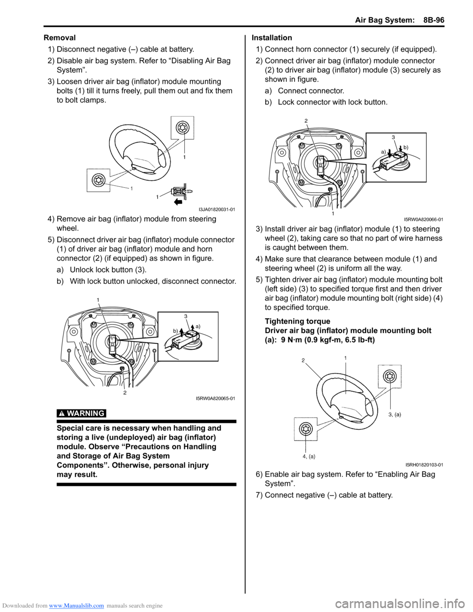
3) Loosen driver air bag (inflator) module mounting
bolts (1) till it turns freely, pull them out and fix them
to bolt clamps.
4) Remove air bag (inflator) module from steering
wheel.
5) Disconnect driver air bag (inflator) module connector
(1) of driver air bag (inflator) module and horn
connector (2) (if equipped) as shown in figure.
a) Unlock lock button (3).
b) With lock button unlocked, disconnect connector.
WARNING!
Special care is necessary when handling and
storing a live (undeployed) air bag (inflator)
module. Observe “Precautions on Handling
and Storage of Air Bag System
Components”. Otherwise, personal injury
may result.
Installation
1) Connect horn connector (1) securely (if equipped).
2) Connect driver air bag (inflator) module connector
(2) to driver air bag (inflator) module (3) securely as
shown in figure.
a) Connect connector.
b) Lock connector with lock button.
3) Install driver air bag (inflator) module (1) to steering
wheel (2), taking care so that no part of wire harness
is caught between them.
4) Make sure that clearance between module (1) and
steering wheel (2) is uniform all the way.
5) Tighten driver air bag (inflator) module mounting bolt
(left side) (3) to specified torque first and then driver
air bag (inflator) module mounting bolt (right side) (4)
to specified torque.
Tightening torque
Driver air bag (inflator) module mounting bolt
(a): 9 N·m (0.9 kgf-m, 6.5 lb-ft)
6) Enable air bag system. Refer to “Enabling Air Bag
System”.
7) Connect negative (–) cable at battery.
I3JA01820031-01
1
2
a)
b)3
I5RW0A820065-01
2
1
b)
a)3
I5RW0A820066-01
I5RH01820103-01
Page 1369 of 1556

Downloaded from www.Manualslib.com manuals search engine Instrumentation / Driver Info. / Horn: 9C-17
Outside Air Temperature Sensor Removal and
Installation (If Equipped)
S6RW0D9306013
Removal
1) Disconnect negative (–) cable at battery.
2) Remove front bumper referring to “Front Bumper
and Rear Bumper Components in Section 9K”.
3) Disconnect connector from outside air temperature
sensor.
4) Remove outside air temperature sensor (1) from
front bumper member.
Installation
Reverse removal procedure for installation.
Outside Air Temperature Sensor Inspection (If
Equipped)
S6RW0D9306014
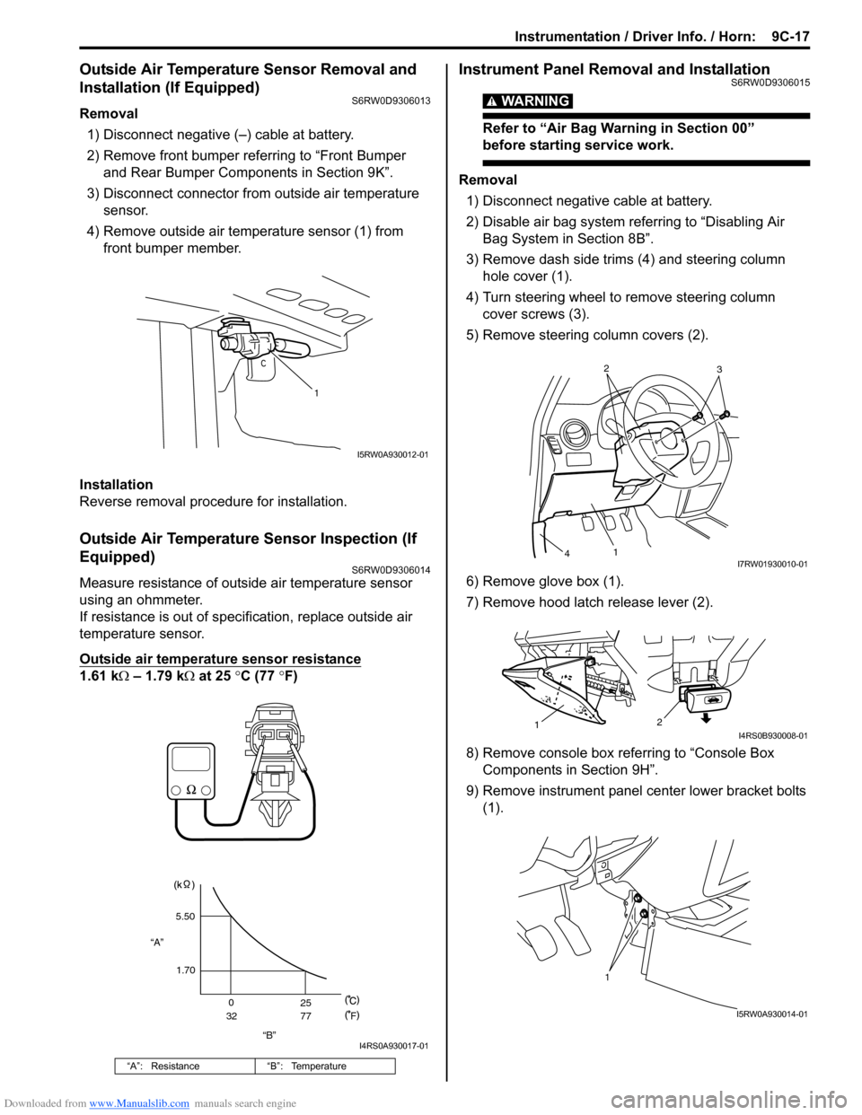
Measure resistance of outside air temperature sensor
using an ohmmeter.
If resistance is out of specification, replace outside air
temperature sensor.
Outside air temperature sensor resistance
1.61 kΩ – 1.79 kΩ at 25 °C (77 °F)
Instrument Panel Removal and InstallationS6RW0D9306015
WARNING!
Refer to “Air Bag Warning in Section 00”
before starting service work.
Removal
1) Disconnect negative cable at battery.
2) Disable air bag system referring to “Disabling Air
Bag System in Section 8B”.
3) Remove dash side trims (4) and steering column
hole cover (1).
4) Turn steering wheel to remove steering column
cover screws (3).
5) Remove steering column covers (2).
6) Remove glove box (1).
7) Remove hood latch release lever (2).
8) Remove console box referring to “Console Box
Components in Section 9H”.
9) Remove instrument panel center lower bracket bolts
(1).
“A”: Resistance “B”: Temperature
1
I5RW0A930012-01
“B” “A”5.50
1.70
0
3225
77
F
I4RS0A930017-01
2
3
1
4I7RW01930010-01
2
1I4RS0B930008-01
1
I5RW0A930014-01