2006 SUZUKI SX4 wheel bolts
[x] Cancel search: wheel boltsPage 451 of 1556

Downloaded from www.Manualslib.com manuals search engine Front Suspension: 2B-14
Front Wheel Hub, Disc, Bolt and Bearing CheckS6RW0D2206008
• Inspect each wheel disc for dents, distortion and
cracks.
A disc in badly damaged condition must be replaced.
• Check rust of installation face inside of wheel disc.
As rust affects adversely, remove it thoroughly.
• Check tightness of wheel nuts and, if necessary,
retighten them to specified torque.
Tightening torque
Wheel nut: 85 N·m (8.5 kgf-m, 61.5 lb-ft)
• Check wear of wheel bearing. When measuring thrust
play, apply a dial gauge to wheel hub as shown in
figure.
Front wheel bearing thrust play
Limit: 0.1 mm (0.004 in.)
• Check wheel bearing noise and smooth wheel rotation
by rotating wheel.
If defective, replace bearing.
Suspension Control Arm / Bushing Removal
and Installation
S6RW0D2206009
CAUTION!
When removal and installing steering
knuckle assembly, be careful not to damage
dust boots of control arm joint by drive shaft
dust cover and brake dust cover.
Removal
1) Hoist vehicle and remove wheel.
2) Remove steering knuckle with front wheel hub
referring to step 2) to 5), 7) to 11) of “Removal” under
“Front Wheel Hub, Steering Knuckle and Wheel
Bearing Removal and Installation”.
3) Remove suspension control arm bolts (1).
4) Remove suspension control arm (2).
I3RM0A220034-01
21
I5RW0A220019-01
Page 452 of 1556

Downloaded from www.Manualslib.com manuals search engine 2B-15 Front Suspension:
Installation
1) Install suspension control arm as shown but tighten
suspension control arm bolts (1) only temporarily.
CAUTION!
Use new control arm bolt.
2) Install steering knuckle with front wheel hub referring
to step 7) to 17) of “Installation” under “Front Wheel
Hub, Steering Knuckle and Wheel Bearing Removal
and Installation”.
3) Install wheel and tighten wheel nuts to specified
torque.
Tightening torque
Wheel nut: 85 N·m (8.5 kgf-m, 61.5 lb-ft)
4) Lower hoist and vehicle in unloaded condition,
tighten new control arm bolts to specified torque.
Tightening torque
Suspension control arm bolt (a): 95 N·m (9.5
kgf-m, 69.0 lb-ft)
5) Confirm front wheel alignment referring to “Front
Wheel Alignment Inspection and Adjustment”.
Suspension Control Arm / Bushing
Disassembly and Assembly
S6RW0D2206010
Disassembly
1) Cut off bushing flange (rubber) (1) with knife.
2) Push out bushing by using hydraulic press (2) and
special tools.
Special tool
(A): 09943–76310
(B): 09913–75821
1
1
I5RW0A220020-01
(a)
I5RW0A220021-01
I4RS0B220019-01
2
(A) (B)
I4RS0B220020-01
Page 455 of 1556

Downloaded from www.Manualslib.com manuals search engine Front Suspension: 2B-18
Front Suspension Frame, Stabilizer Bar and/or
Bushing Removal and Installation
S6RW0D2206015
WARNING!
When supporting and installing front
suspension frame, be sure to apply some
supporting equipment (such as mission jack)
at well-balanced position in the center
section of front suspension frame so as to
prevent from its drop. Otherwise drop and
injure.
CAUTION!
When removal and installing suspension
control arm, be careful not to damage dust
boots of suspension control arm joint by
drive shaft dust cover and brake dust cover.
Removal
1) Disconnect negative (–) cable at battery.
2) Remove air cleaner assembly referring to “Air
Cleaner Assembly Removal and Installation in
Section 1D”.
3) Remove hood referring to “Hood Removal and
Installation in Section 9J”.
4) Hoist vehicle and remove front wheels.
5) Remove exhaust No.1, No.2 and center pipes
referring to “Exhaust System Components in Section
1K”.
6) Remove steering gear case mounting bolt referring
to “Steering Gear Case Assembly Components in
Section 6C”.
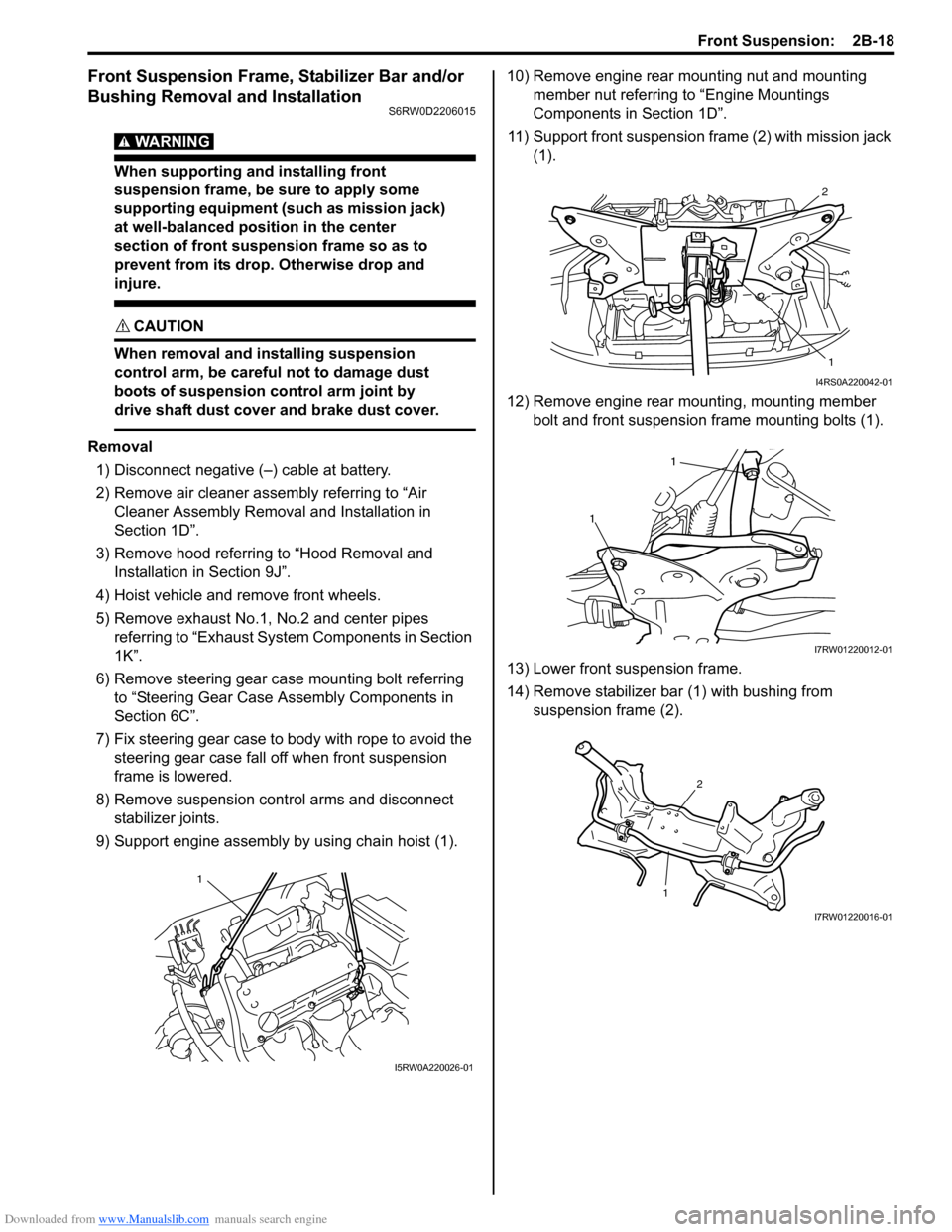
7) Fix steering gear case to body with rope to avoid the
steering gear case fall off when front suspension
frame is lowered.
8) Remove suspension control arms and disconnect
stabilizer joints.
9) Support engine assembly by using chain hoist (1).10) Remove engine rear mounting nut and mounting
member nut referring to “Engine Mountings
Components in Section 1D”.
11) Support front suspension frame (2) with mission jack
(1).
12) Remove engine rear mounting, mounting member
bolt and front suspension frame mounting bolts (1).
13) Lower front suspension frame.
14) Remove stabilizer bar (1) with bushing from
suspension frame (2).
1
I5RW0A220026-01
2
1
I4RS0A220042-01
1
1
I7RW01220012-01
12
I7RW01220016-01
Page 457 of 1556

Downloaded from www.Manualslib.com manuals search engine Front Suspension: 2B-20
12) Install exhaust No.1, No.2 and center pipe referring
to “Exhaust System Components in Section 1K”.
13) Install wheel and tighten nut to specified torque.
Tightening torque
Wheel nut: 85 N·m (8.5 kgf-m, 61.5 lb-ft)
14) Install air cleaner assembly referring to “Air Cleaner
Assembly Removal and Installation in Section 1D”.
15) Install hood referring to “Hood Removal and
Installation in Section 9J”.
16) Lower hoist and vehicle in unloaded condition,
tighten suspension control arm bolts to specified
torque.
Tightening torque
Suspension control arm bolt: 95 N·m (9.5 kgf-m,
69.0 lb-ft)
17) Connect negative (–) cable at battery.
18) Confirm front wheel alignment referring to “Front
Wheel Alignment Inspection and Adjustment”.
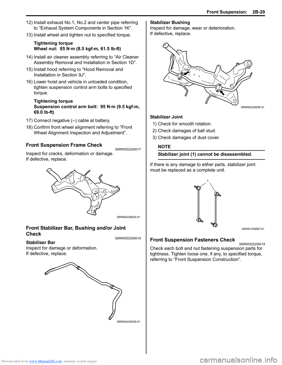
Front Suspension Frame CheckS6RW0D2206017
Inspect for cracks, deformation or damage.
If defective, replace.
Front Stabilizer Bar, Bushing and/or Joint
Check
S6RW0D2206018
Stabilizer Bar
Inspect for damage or deformation.
If defective, replace.Stabilizer Bushing
Inspect for damage, wear or deterioration.
If defective, replace.
Stabilizer Joint
1) Check for smooth rotation.
2) Check damages of ball stud.
3) Check damages of dust cover.
NOTE
Stabilizer joint (1) cannot be disassembled.
If there is any damage to either parts, stabilizer joint
must be replaced as a complete unit.
Front Suspension Fasteners CheckS6RW0D2206019
Check each bolt and nut fastening suspension parts for
tightness. Tighten loose one, if any, to specified torque,
referring to “Front Suspension Construction”.
I5RW0A220034-01
I5RW0A220035-01
I5RW0A220036-01
1
I4RH01220007-01
Page 464 of 1556

Downloaded from www.Manualslib.com manuals search engine 2C-5 Rear Suspension:
Installation
1) Install spring upper seat (1) to vehicle body and
lower seat (2) to rear axle.
CAUTION!
For proper installing direction of spring
upper seat (1) and spring lower seat (2), refer
to the figure.
2) Install coil spring (3) on spring lower seat (2) of rear
axle and place coil spring end (4) onto spring lower
seat (2) as shown in figure.
3) Jack up rear axle and then install shock absorbers
(1) lower end to rear axle.
Install washers and tighten shock absorber lower
nuts (2) temporarily at this step.4) Remove floor jacks from rear axle.
5) Remount rear differential (4WD model) referring to
“Rear Differential Dismounting and Remounting in
Section 3B”.
6) Install wheel and tighten wheel nuts to specified
torque.
Tightening torque
Wheel nut: 85 N·m (8.5 kgf-m, 61.5 lb-ft)
7) Lower hoist and bounce vehicle up and down
several times to stabilize suspension.
8) Tighten absorber lower nuts and rear axle bolts to
specified torque.
NOTE
When tightening these nuts and bolts, be
sure that vehicle is not on hoist and in
unloaded condition.
Tightening torque
Rear shock absorber lower nut: 90 N·m (9.0 kgf-
m, 65.0 lb-ft)
Rear axle bolt: 73 N·m (7.3 kgf-m, 53.0 lb-ft)
9) Install rear fender lining.
Spring Upper Seat / Spring Lower Seat
Inspection
S6RW0D2306006
Inspect for cracks, deformation or damage.
Replace any defective part.[A]: Left side F: Vehicle forward
[B]: Right side “a”: 10 mm max
U: Up ward
I7RW01230004-02
1
2I4RS0A230012-01
I4RS0A230015-01
Page 465 of 1556

Downloaded from www.Manualslib.com manuals search engine Rear Suspension: 2C-6
Rear Axle Removal and InstallationS6RW0D2306007
CAUTION!
Do not drop brake fluid onto painted surface.
Painted surfaces will be damaged.
Removal
1) Hoist vehicle and remove exhaust center pipe and
muffler.
2) Disconnect rear height sensor link (if equipped) from
rear axle referring to “Height Sensor Removal and
Installation (If Equipped) in Section 9B”.
3) Remove rear wheel, rear brake drum and rear wheel
hub referring to “Removal” under “Rear Wheel Hub
Assembly Removal and Installation”.
4) Disconnect brake pipe (1) from brake flexible hoses
(2) and remove E-rings (3).
5) Remove coil springs referring to “Rear Coil Spring
Removal and Installation”.
6) Disconnect wheel speed sensor clamp (1) and
parking brake cable nuts (2) from rear axle.
7) While supporting rear axle at both ends, remove rear
axle bolts and then remove rear axle from chassis by
lowering floor jack gradually.
8) Remove brake pipes from rear axle, if necessary.Installation
CAUTION!
Never reuse rear axle bolts and rear wheel
hub mounting bolts.
1) Install brake pipes to rear axle, if removed.
2) Using floor jacks, install rear axle and new rear axle
bolts (1) and tighten bolts temporarily.
3) Install coil spring referring to “Rear Coil Spring
Removal and Installation”.
4) Install rear wheel hub and wheel speed sensor
referring to “Installation” under “Rear Wheel Hub
Assembly Removal and Installation”.
5) Connect brake flexible hoses (1) to bracket on rear
axle with E-ring (2) and tighten brake pipe flare nuts
(3) to specified torque.
Tightening torque
Brake pipe flare nut (a): 16 N·m (1.6 kgf-m, 11.5
lb-ft)
1 3
2
I5RW0A230013-01
2
1
I5RW0A230015-01
1
I5RW0A230017-01
2
1
3,(a)
I5RW0A230019-01
Page 466 of 1556

Downloaded from www.Manualslib.com manuals search engine 2C-7 Rear Suspension:
6) Connect rear height sensor link (if equipped) to rear
axle referring to “Height Sensor Removal and
Installation (If Equipped) in Section 9B”.
7) Install exhaust center pipe and muffler.
8) After installing removed parts, bleed air from brake
system referring to “Air Bleeding of Brake System in
Section 4A”. And then adjust parking brake cable
referring to “Parking Brake Inspection and
Adjustment in Section 4D”.
9) Install wheel and tighten wheel nuts to specified
torque.
Tightening torque
Wheel nut: 85 N·m (8.5 kgf-m, 61.5 lb-ft)
10) Lower hoist and bounce vehicle up and down
several times to stabilize suspension.
11) Tightening shock absorber lower nuts and rear axle
bolts to specified torque.
NOTE
When tightening these nuts and bolts, be
sure that vehicle is not on hoist and in
unloaded condition.
Tightening torque
Rear shock absorber lower nut: 90 N·m (9.0 kgf-
m, 65.0 lb-ft)
Rear axle bolt: 73 N·m (7.3 kgf-m, 53.0 lb-ft)
12) Perform brake test (foot brake and parking brake).
13) Check each installed parts for brake fluid leakage.
Rear Axle and Coil Spring InspectionS6RW0D2306009
• Inspect for cracks, deformation or damage.
• Inspect bushing for damage, wear or breakage.
Replace any defective part.
Rear Axle Bush InspectionS6RW0D2306010
Inspect for cracks, deformation or damage. If necessary,
replace rear axle assembly.
Rear Wheel Disc, Bolt and Bearing InspectionS6RW0D2306011
• Check tightness of wheel nuts and, if necessary,
retighten to specified torque.
• Check wheel disc deformation, damage, crack and
etc.
Replace defective disc with new one.
• Check installation face inside of wheel disc for rust.
As rust affects adversely, remove it thoroughly.
Tightening torque
Wheel nut: 85 N·m (8.5 kgf-m, 61.5 lb-ft)
• Check wear of wheel bearings. When measuring
thrust play, apply a dial gauge to axle shaft center.
When the thrust play exceeds limit, replace bearing.
Rear wheel bearing thrust play
Limit: 0.1 mm (0.004 in.)
• Check noise and smooth rotation of wheel by rotating
wheel. If it is defective, replace bearing.
(a)I5RW0A230022-01
I3RM0A230049-01
I3RM0A230050-01
Page 467 of 1556

Downloaded from www.Manualslib.com manuals search engine Rear Suspension: 2C-8
Rear Wheel Hub Assembly Removal and
Installation
S6RW0D2306012
CAUTION!
Do not allow brake fluid to get on painted
surfaces. Painted surface will be damaged.
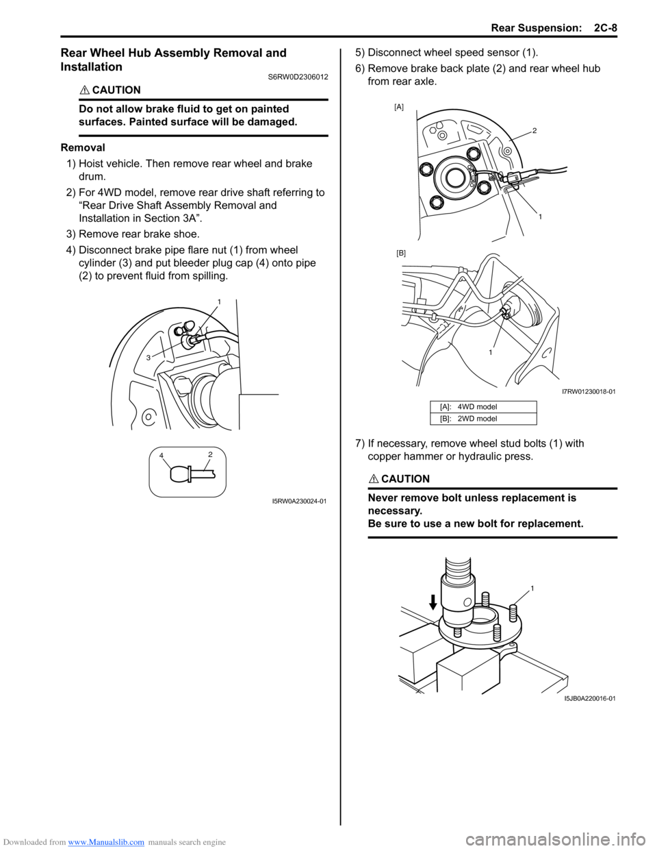
Removal
1) Hoist vehicle. Then remove rear wheel and brake
drum.
2) For 4WD model, remove rear drive shaft referring to
“Rear Drive Shaft Assembly Removal and
Installation in Section 3A”.
3) Remove rear brake shoe.
4) Disconnect brake pipe flare nut (1) from wheel
cylinder (3) and put bleeder plug cap (4) onto pipe
(2) to prevent fluid from spilling.5) Disconnect wheel speed sensor (1).
6) Remove brake back plate (2) and rear wheel hub
from rear axle.
7) If necessary, remove wheel stud bolts (1) with
copper hammer or hydraulic press.
CAUTION!
Never remove bolt unless replacement is
necessary.
Be sure to use a new bolt for replacement.
1
42
3
I5RW0A230024-01
[A]: 4WD model
[B]: 2WD model
2 [A]
1 [B]
1
I7RW01230018-01
1
I5JB0A220016-01