2006 SUZUKI SX4 torque
[x] Cancel search: torquePage 358 of 1556

Downloaded from www.Manualslib.com manuals search engine 1E-2 Engine Lubrication System:
Diagnostic Information and Procedures
Oil Pressure CheckS6RW0D1504001
WARNING!
To avoid the danger of being burned, do not
touch the exhaust system when the system is
hot. Any service on the exhaust system
should be performed when the system is
cool.
NOTE
Prior to checking oil pressure, check the
following.
• Oil level in oil pan
If oil level is low, add oil up to full level
mark (hole) (1) on oil level gauge referring
to “Engine Oil and Filter Change in Section
0B”.
• Oil quality
If oil is discolored or deteriorated, change
it. For particular oil to be used, refer to
“Engine Oil and Filter Change in Section
0B”.
• Oil leaks
If leak is found, repair it.
1) Disconnect oil pressure switch coupler (1).
2) Remove oil pressure switch (2) from cylinder block.3) Install special tools (oil pressure gauge) to vacated
threaded hole of oil pressure switch.
Special tool
(A): 09915–77310
(B): 09915–78211
4) Start engine and warm engine up to normal
operating temperature.
NOTE
Be sure to shift transaxle gear shift lever in
“Neutral”, set parking brake and block drive
wheels.
5) After warming up, raise engine speed to 4,000 r/min.
and measure oil pressure.
Oil pressure specification
More than 270 kPa (2.7 kgf/cm2, 39.8 psi) at 4,000
r/min. (rpm)
6) After checking oil pressure, stop engine and remove
oil pressure gauge and attachment.
7) Before reinstalling oil pressure switch (2), be sure to
wrap its screw threads with sealing tape (1) and
tighten switch to specified torque.
NOTE
If sealing tape edge is bulged out from screw
threads of switch, cut it off.
Tightening torque
Oil pressure switch (a): 13 N·m (1.3 kgf-m, 9.5
lb-ft)
2. Low level mark (hole)
I2RH0B150002-01
I2RH0B150003-01
I2RH0B150004-01
I2RH0B150005-01
Page 359 of 1556

Downloaded from www.Manualslib.com manuals search engine Engine Lubrication System: 1E-3
8) Start engine and check oil pressure switch for oil
leakage. If oil leakage is found, repair it.
9) Connect oil pressure switch coupler (1).
Repair Instructions
Oil Pan and Oil Pump Strainer ComponentsS6RW0D1506001
I2RH0B150006-01
1
23
4
(a) 5
(b) 6
(b) 8
(b) 9
(b) 7
10
(c)10
(c)
11 12
(d) 13
(d) 1514
I5RH0A150002-02
1. Oil pan:
Apply sealant 99000-31260 to
mating surface.6. Strainer bolt 11. Dowel pin : 35 N⋅m (3.5 kgf-m, 25.5 lb-ft)
2. Strainer 7. Bracket bolt 12. Baffle plate : Tighten 11 N⋅m (1.1 kgf-m, 8.0 lb-
ft) by the specified procedure.
3. O-ring 8. Oil pan nut 13. Baffle plate bolt : 55 N⋅m (5.5 kgf-m, 40.0 lb-ft)
4. Gasket 9. Oil pan bolt
(M6)14. Clutch housing lower plate (M/T
vehicle) or torque converter housing
lower plate (A/T vehicle):11 N⋅m (1.1 kgf-m, 8.0 lb-ft)
5. Drain plug 10. Oil pan bolt
(M10)15. Lower plate bolt : Do not reuse.
Page 360 of 1556

Downloaded from www.Manualslib.com manuals search engine 1E-4 Engine Lubrication System:
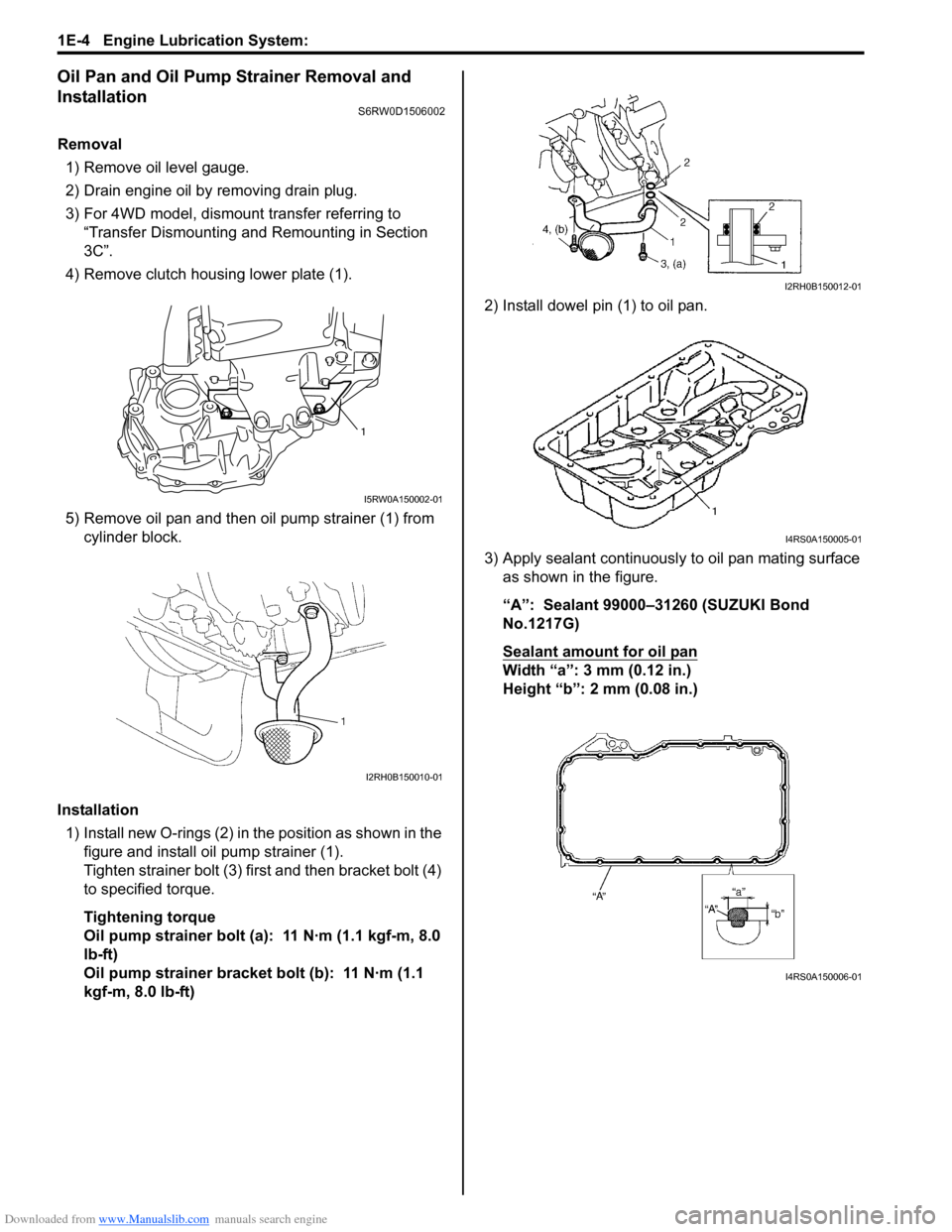
Oil Pan and Oil Pump Strainer Removal and
Installation
S6RW0D1506002
Removal
1) Remove oil level gauge.
2) Drain engine oil by removing drain plug.
3) For 4WD model, dismount transfer referring to
“Transfer Dismounting and Remounting in Section
3C”.
4) Remove clutch housing lower plate (1).
5) Remove oil pan and then oil pump strainer (1) from
cylinder block.
Installation
1) Install new O-rings (2) in the position as shown in the
figure and install oil pump strainer (1).
Tighten strainer bolt (3) first and then bracket bolt (4)
to specified torque.
Tightening torque
Oil pump strainer bolt (a): 11 N·m (1.1 kgf-m, 8.0
lb-ft)
Oil pump strainer bracket bolt (b): 11 N·m (1.1
kgf-m, 8.0 lb-ft)2) Install dowel pin (1) to oil pan.
3) Apply sealant continuously to oil pan mating surface
as shown in the figure.
“A”: Sealant 99000–31260 (SUZUKI Bond
No.1217G)
Sealant amount for oil pan
Width “a”: 3 mm (0.12 in.)
Height “b”: 2 mm (0.08 in.)
1
I5RW0A150002-01
I2RH0B150010-01
I2RH0B150012-01
I4RS0A150005-01
I4RS0A150006-01
Page 361 of 1556

Downloaded from www.Manualslib.com manuals search engine Engine Lubrication System: 1E-5
4) Install oil pan to cylinder block temporarily.
5) Insert dowel pin (1) in hole (2) of oil pan in order to
locate oil pan precisely.
NOTE
Dowel pin is available as a spare part (part
number: 04211–13189).
6) After fitting oil pan to cylinder block, run in securing
bolts and start tightening at the center: move wrench
outward, tightening one bolt at a time. Tighten bolts
and nuts to specified torque.
Tightening torque
Oil pan bolt (M6) (a): 11 N·m (1.1 kgf-m, 8.0 lb-ft)
Oil pan bolt (M10) (c): 55 N·m (5.5 kgf-m, 40.0 lb-
ft)
Oil pan nut (e): 11 N·m (1.1 kgf-m, 8.0 lb-ft)
7) After applying engine oil to drain plug, install new
gasket and drain plug to oil pan.
Tighten drain plug to specified torque.
Tightening torque
Oil pan drain plug (b): 35 N·m (3.5 kgf-m, 25.5 lb-
ft)
8) Tighten transaxle stiffener bolts to specified torque.
Tightening torque
Transaxle stiffener bolt (d): 55 N·m (5.5 kgf-m,
40.0 lb-ft)9) Install clutch housing lower plate (1) and then tighten
clutch housing lower plate bolt to specified torque.
Tightening torque
Clutch housing lower plate bolt (a): 11 N·m (1.1
kgf-m, 8.0 lb-ft)
10) For 4WD model, remount transfer referring to
“Transfer Dismounting and Remounting in Section
3C”.
11) Install oil level gauge.
12) Refill engine with engine oil referring to “Engine Oil
and Filter Change in Section 0B”.
13) Verify that there is no engine oil leakage and exhaust
gas leakage at each connection.
Oil Pan and Oil Pump Strainer CleaningS6RW0D1506003
• Clean sealing surface between oil pan and cylinder
block.
Remove oil, old sealant, and dust from sealing
surface.
• Clean oil pump strainer screen (1).
21I4RS0A150007-01
(a)
(b)
(c)(e)
(d)I4RS0A150008-01
1,(a)
I5RW0A150003-01
I2RH0B150016-01
Page 363 of 1556

Downloaded from www.Manualslib.com manuals search engine Engine Lubrication System: 1E-7
Reassembly
1) Wash, clean and then dry all disassembled parts.
2) Apply thin coat of engine oil to inner and outer rotors,
oil seal lip portion, inside surfaces of oil pump case
and plate.
3) Install outer (1) and inner rotors (2) to oil pump case.
4) Apply engine oil to relief valve (1) and spring (2), and
install them with retainer (3) and new circlip (4) to
rotor plate (5).
5) Install rotor plate and tighten all bolts to specified
torque. After installing plate, check to be sure that
rotors turn smoothly by hand (0.3 N⋅m (0.03 kgf-m,
0.25 lb-ft) torque or below).
Tightening torque
Oil pump rotor plate bolt (a): 11 N·m (1.1 kgf-m,
8.0 lb-ft)Oil Pump InspectionS6RW0D1506007
Oil Seal
Check oil seal lip for fault or other damage. Replace as
necessary.
Oil Pump
• Check outer (1) and inner rotors (2), rotor plate, and
oil pump case for excessive wear or damage.
• Check relief valve (1) for excessive wear or damage
and operates smoothly.
I2RH0B150019-01
I3RM0A150005-01
I2RH0B150022-01
I2RH0B150023-01
I2RH0B150019-01
I2RH0B150025-01
Page 365 of 1556

Downloaded from www.Manualslib.com manuals search engine Engine Lubrication System: 1E-9
Specifications
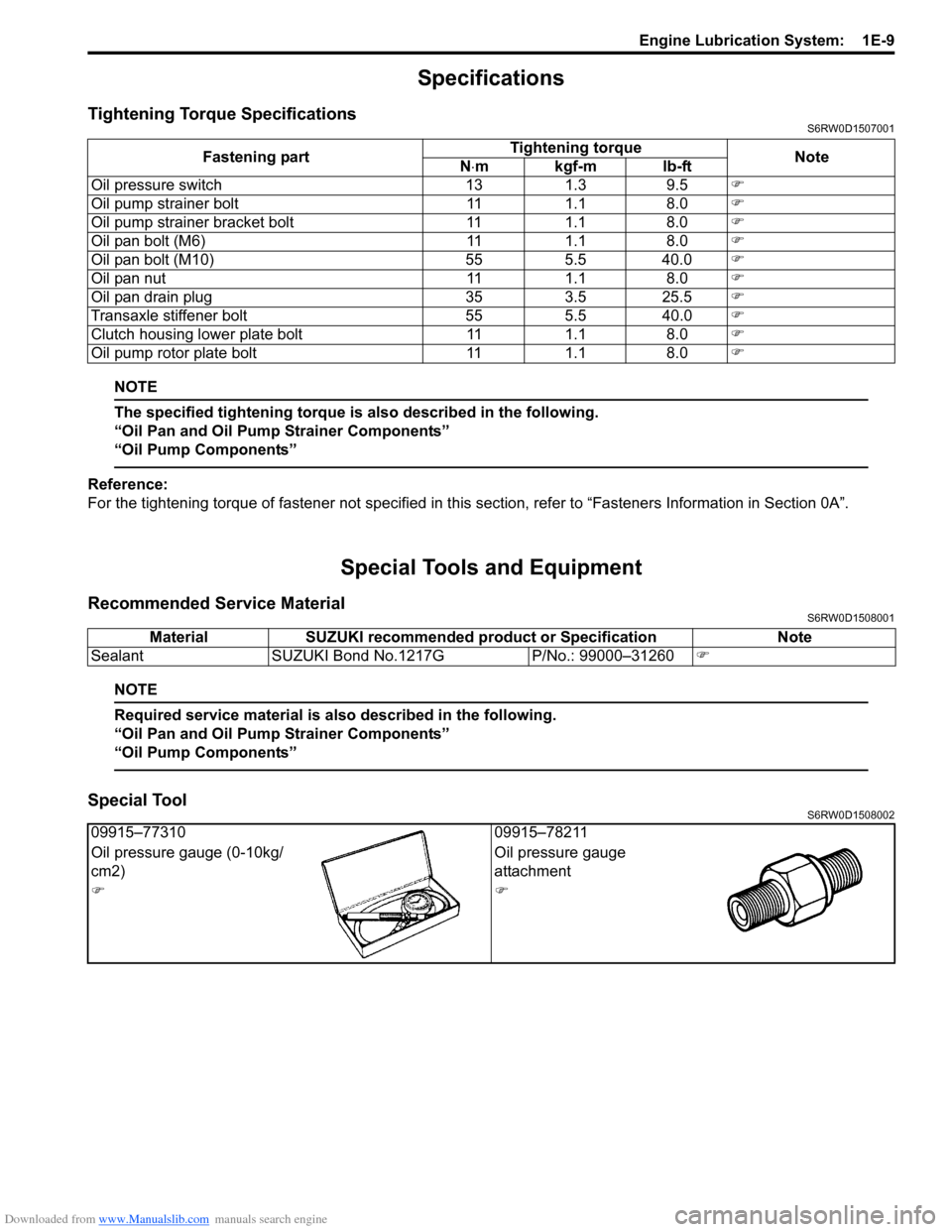
Tightening Torque SpecificationsS6RW0D1507001
NOTE
The specified tightening torque is also described in the following.
“Oil Pan and Oil Pump Strainer Components”
“Oil Pump Components”
Reference:
For the tightening torque of fastener not specified in this section, refer to “Fasteners Information in Section 0A”.
Special Tools and Equipment
Recommended Service MaterialS6RW0D1508001
NOTE
Required service material is also described in the following.
“Oil Pan and Oil Pump Strainer Components”
“Oil Pump Components”
Special ToolS6RW0D1508002
Fastening partTightening torque
Note
N⋅mkgf-mlb-ft
Oil pressure switch 13 1.3 9.5�)
Oil pump strainer bolt 11 1.1 8.0�)
Oil pump strainer bracket bolt 11 1.1 8.0�)
Oil pan bolt (M6) 11 1.1 8.0�)
Oil pan bolt (M10) 55 5.5 40.0�)
Oil pan nut 11 1.1 8.0�)
Oil pan drain plug 35 3.5 25.5�)
Transaxle stiffener bolt 55 5.5 40.0�)
Clutch housing lower plate bolt 11 1.1 8.0�)
Oil pump rotor plate bolt 11 1.1 8.0�)
Material SUZUKI recommended product or Specification Note
Sealant SUZUKI Bond No.1217G P/No.: 99000–31260�)
09915–77310 09915–78211
Oil pressure gauge (0-10kg/
cm2)Oil pressure gauge
attachment
�)�)
Page 374 of 1556

Downloaded from www.Manualslib.com manuals search engine 1F-9 Engine Cooling System:
5) Remove cooling fan mounting bolts (1).
6) Remove radiator cooling fan assembly (2).
Installation
Reverse removal procedure for installation noting the
following.
• Refill cooling system referring to Step 7) to 17) of
“Cooling System Flush and Refill”.
• After installation, verify there is no coolant leakage at
each connection.
Radiator Cooling Fan Disassembly and
Reassembly
S6RW0D1606018
Disassembly
1) Remove fan (1) from cooling fan motor (2).
2) Remove fan motor (2) from cooling fan guide (3).
Reassembly
Reverse disassembly procedures for reassembly.
Radiator On-Vehicle Inspection and CleaningS6RW0D1606012
Inspection
Check radiator for leakage or damage. Straighten bent
fins, if any.
Cleaning
Clean frontal area of radiator cores.
Radiator Removal and InstallationS6RW0D1606013
Removal
1) Disconnect negative cable at battery.
2) Drain coolant referring to “Cooling System Draining”.
3) Remove front bumper referring to “Front Bumper
and Rear Bumper Components in Section 9K”.
4) Remove cooling fan assembly referring to “Radiator
Cooling Fan Assembly Removal and Installation”.
5) Remove condenser fan referring to “Condenser
Cooling Fan Removal and Installation in Section 7B”.
6) Remove radiator outlet hose from radiator.
7) Remove radiator from vehicle.
Installation
Reverse removal procedures, noting the following.
Tighten radiator support bracket bolts to specified
torque.
Tightening torque
Radiator support bracket bolt: 33 N·m (3.3 kgf-m,
24.0 lb-ft)
• Refill cooling system referring to Step 7) to 17) of
“Cooling System Flush and Refill”.
• After installation, verify there is no coolant leakage
each connection.
I5RW0C160014-01
I5RW0C160005-01
I2RH01160014-01
Page 375 of 1556

Downloaded from www.Manualslib.com manuals search engine Engine Cooling System: 1F-10
Water Pump / Generator Drive Belt Tension
Inspection and Adjustment
S6RW0D1606014
WARNING!
• Disconnect negative cable at battery
before checking and adjusting belt
tension.
• To help avoid danger of being burned, do
not remove radiator cap while engine and
radiator are still hot. Scalding fluid and
steam can be blown out under pressure if
cap is taken off too soon.
1) Inspect belt for cracks, cuts, deformation, wear and
cleanliness. If it is necessary to replace belt, refer to
“Water Pump / Generator Drive Belt Removal and
Installation”.
2) Check belt for tension. Belt is in proper tension when
it deflects the following specification under thumb
pressure (about 100 N (10kgf, 22 lbs.).
If belt tension is out of specification, go to next steps.
Water pump / generator drive belt tension
“a”: 4.5 – 5.5 mm (0.18 – 0.22 in.) as deflection /
100 N (10kgf, 22lbs)
NOTE
When replacing belt with a new one, adjust
belt tension to 4.0 – 4.5 mm (0.16 – 0.18 in.).
3) After loosening generator bracket bolts (2) and pivot
bolt (3), adjust belt tension to specification described
at step 2) by loosening / tightening generator adjust
bolt (1).
4) Tighten generator bracket bolts and pivot bolt as
specified torque.
Tightening torque
Generator bracket bolt (a): 25 N·m (2.5 kgf-m,
18.0 lb-ft)
Generator pivot bolt (b): 50 N·m (5.0 kgf-m, 36.0
lb-ft)5) Check belt tension for specification after turning
crankshaft two rotations clockwise.
6) Tighten generator adjusting bolt (1) as specified
torque.
Tightening torque
Generator adjusting bolt (c): Tighten 7.0 N⋅m
(0.7 kgf-m, 5.0 lb-ft) by the specified procedure.
7) Connect negative cable at battery.
Water Pump / Generator Drive Belt Removal and
Installation
S6RW0D1606015
Removal
1) Disconnect negative cable at battery.
2) If vehicle equipped with A/C, remove compressor
drive belt before removing water pump belt (1).
Refer to “Compressor Drive Belt Removal and
Installation in Section 7B” or “Compressor Drive Belt
Removal and Installation in Section 7B”.
3) Loosen generator bracket bolts (2) and generator
pivot bolt (3).
4) Loosen generator adjusting bolt (4), and then
remove water pump belt.
a
I5RW0C160006-01
1, (c)
2, (a)
3, (b)
I5RW0C160007-01
4
23
1
I5RW0C160008-01