2006 SUZUKI SX4 torque
[x] Cancel search: torquePage 405 of 1556

Downloaded from www.Manualslib.com manuals search engine Ignition System: 1H-10
Specifications
Tightening Torque SpecificationsS6RW0D1807001
Reference:
For the tightening torque of fastener not specified in this section, refer to “Fasteners Information in Section 0A”.
Special Tools and Equipment
Special ToolS6RW0D1808001
Fastening partTightening torque
Note
N⋅mkgf-mlb-ft
Spark plug 25 2.5 18.0�)
Ignition coil bolt 11 1.1 8.0�)
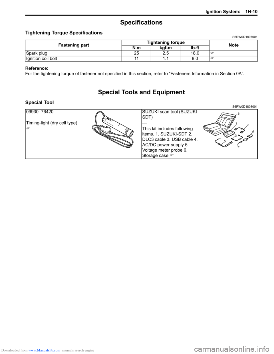
09930–76420 SUZUKI scan tool (SUZUKI-
SDT)
Timing-light (dry cell type) —
�)This kit includes following
items. 1. SUZUKI-SDT 2.
DLC3 cable 3. USB cable 4.
AC/DC power supply 5.
Voltage meter probe 6.
Storage case �)
1
2
34
56
Page 407 of 1556

Downloaded from www.Manualslib.com manuals search engine Starting System: 1I-2
Condition Possible cause Correction / Reference Item
Motor not running (No
operating sound of
magnetic switch)Transmission range sensor is not in P or
N, or not adjusted (A/T model)Shift in P or N, or adjust sensor. (A/T model)
Battery run downRecharge battery.
Battery voltage too low due to battery
deteriorationReplace battery.
Poor contact in battery terminal
connectionRetighten or replace.
Loose grounding cable connectionRetighten.
Fuse set loose or blown offTighten or replace.
Poor contacting action of ignition switch
and magnetic switchReplace.
Lead wire coupler loose in placeRetighten.
Open-circuit between ignition switch and
magnetic switchRepair.
Open-circuit in pull-in coilReplace magnetic switch.
Brushes are seating poorly or worn
downRepair or replace.
Poor sliding of plunger and/or pinionRepair.
Faulty starting motor control relay“Main Relay, Fuel Pump Relay, Starting Motor
Control Relay, Throttle Actuator Control Relay
and Radiator Cooling Fan Relay Inspection in
Section 1C”.
Faulty ECM and its circuit“Inspection of ECM and Its Circuits in Section
1A”.
Motor not running
(Operating sound of
magnetic switch heard)Battery run downRecharge battery.
Battery voltage too low due to battery
deteriorationReplace battery.
Loose battery cable connectionsRetighten.
Burnt main contact point, or poor
contacting action of magnetic switchReplace magnetic switch.
Brushes are seating poorly or worn
downRepair or replace.
Weakened brush springReplace.
Burnt commutatorReplace armature.
Layer short-circuit of armatureReplace.
Crankshaft rotation obstructedRepair.
Starting motor running
but too slow (small
torque) (If battery and
wiring are satisfactory,
inspect starting motor)Insufficient contact of magnetic switch
main contactsReplace magnetic switch.
Layer short-circuit of armatureReplace.
Disconnected, burnt or worn
commutatorRepair commutator or replace armature.
Worn brushesReplace brush.
Weakened brush springsReplace spring.
Burnt or abnormally worn end bushReplace bush.
Starting motor running,
but not cranking engineWorn pinion tipReplace over-running clutch.
Poor sliding of over-running clutchRepair.
Over-running clutch slippingReplace over-running clutch.
Worn teeth of ring gearReplace flywheel (M/T model) or drive plate (A/
T model).
NoiseAbnormally worn bushReplace bush.
Worn pinion or worn teeth of ring gearReplace over-running clutch, flywheel (M/T
model) or drive plate (A/T model).
Poor sliding of pinion (failure in return
movement)Repair or replace.
Worn internal or planetary gear teethReplace.
Lack of oil in each partLubricate.
Page 409 of 1556

Downloaded from www.Manualslib.com manuals search engine Starting System: 1I-4
Repair Instructions
Starting Motor Dismounting and RemountingS6RW0D1906001
Dismounting
1) Disconnect negative (–) battery lead at battery.
2) Disconnect magnetic switch lead wire (1) and battery cable (2) from starting motor terminals.
3) Detach shift & select control cable bracket from transaxle. (M/T model only)
4) Remove starting motor mount bolt (3) and nut (4).
5) Remove starting motor (5).
Remounting
Reverse the dismounting procedure noting the following.
• Tighten battery cable nut (6) to specified torque.
Tightening torque
Starting motor battery cable nut (a): 9.8 N·m (0.98 kgf-m, 7.0 lb-ft)
I4RS0A190002-01
: 9.8 N⋅m (0.98 kgf-m, 7.0 lb-ft)
Page 414 of 1556

Downloaded from www.Manualslib.com manuals search engine 1I-9 Starting System:
Front Housing Bush
Inspect the bush for wear or damage. Replace if
necessary.
Specifications
Cranking System SpecificationsS6RW0D1907002
Tightening Torque SpecificationsS6RW0D1907003
NOTE
The specified tightening torque is also described in the following.
“Starting Motor Dismounting and Remounting”
“Starting Motor Components”
Reference:
For the tightening torque of fastener not specified in this section, refer to “Fasteners Information in Section 0A”.
Special Tools and Equipment
Recommended Service MaterialS6RW0D1908001
NOTE
Required service material is also described in the following.
“Starting Motor Components”
I2RH01190024-01
Voltage 12 volts
Output 1.2 kW
Rating 30 seconds
Direction of rotation Clockwise as viewed from pinion side
Brush length Standard: 12.3 mm (0.48 in.) Limit: 7.0 mm (0.28 in.)
Number of pinion teeth 8
Performance Condition Guarantee
Around at 20 °C
(68 °F)No load characteristic 11.0 V90 A maximum
2370 r/min minimum
Load characteristic7.5 V
300 A10.65 N⋅m (1.065 kgf-m, 7.70 lb-ft) minimum
840 r/min minimum
Locked characteristic 4.0 V780 A maximum
20 N⋅m (2.0 kgf-m, 14.5 lb-ft) minimum
Magnetic switch operating voltage 8 volts maximum
Fastening partTightening torque
Note
N⋅mkgf-mlb-ft
Starting motor battery cable nut 9.8 0.98 7.0�)
Page 422 of 1556

Downloaded from www.Manualslib.com manuals search engine 1J-8 Charging System:
3) After loosening generator bracket bolts (2) and pivot
bolt (3), adjust belt tension to specification described
at step 2) by loosening / tightening generator adjust
bolt (1).
4) Tighten generator bracket bolts and pivot bolt as
specified torque.
Tightening torque
Generator bracket bolt (a): 25 N·m (2.5 kgf-m,
18.0 lb-ft)
Generator pivot bolt (b): 50 N·m (5.0 kgf-m, 36.0
lb-ft)
5) Check belt tension for specification after turning
crankshaft two rotations clockwise.
6) Tighten generator adjusting bolt (1) as specified
torque.
Tightening torque
Generator adjusting bolt (c): Tighten 7.0 N·m (
0.7 kgf-m, 5.0 lb-ft) by the specified procedure.
7) Connect negative cable at battery.
Water Pump / Generator Drive Belt Removal and
Installation
S6RW0D1A06007
Removal
1) Disconnect negative cable at battery.
2) If vehicle equipped with A/C, remove compressor
drive belt before removing water pump belt (1).
Refer to “Compressor Drive Belt Removal and
Installation in Section 7B” or “Compressor Drive Belt
Removal and Installation in Section 7B”.
3) Loosen generator bracket bolts (2) and generator
pivot bolt (3).
4) Loosen generator adjusting bolt (4), and then
remove water pump belt.
installation
1) Install belt (1) to water pump pulley (2), crankshaft
pulley (3) and generator pulley (4).
2) Adjust belt tension referring to “Water Pump /
Generator Drive Belt Tension Inspection and
Adjustment”.
3) If vehicle equipped with A/C, install compressor drive
belt referring to “Compressor Drive Belt Removal
and Installation in Section 7B” or “Compressor Drive
Belt Removal and Installation in Section 7B”.
4) Connect negative cable at battery.
a
I5RW0C160006-01
1, (c)
2, (a)
3, (b)
I5RW0C160007-01
4
23
1
I5RW0C160008-01
2
1
34I5RW0C160009-01
Page 427 of 1556

Downloaded from www.Manualslib.com manuals search engine Charging System: 1J-13
Specifications
Charging System SpecificationsS6RW0D1A07003
Battery
NOTE
The battery used in each vehicle is one of the following two types, depending on specification.
Battery
: 46B24R (40.6AH/5HR), 55B24R (42.5AH/5HR) 12V
Generator
Tightening Torque SpecificationsS6RW0D1A07004
NOTE
The specified tightening torque is also described in the following.
“Generator Dismounting and Remounting”
“Generator Components”
Reference:
For the tightening torque of fastener not specified in this section, refer to “Fasteners Information in Section 0A”. Battery type 46B24R 55B24R
Rated capacity AH/5HR, 12 Volts 40.6 42.5
Electrolyte L (US / lmp pt.) — 2.8 (5.92 / 4.93)
Type 70 A type
Rated voltage 12 V
Nominal output 70 A
Permissible max. speed 18,000 r/min.
No-load speed 1020 r/min. (rpm)
Regulated voltage 14.2 – 14.8 V (Hi), 12.5 – 13.1 V (Lo)
Exposed brush length Standard: 10.5 mm (0.41 in.)
Limit: 1.5 mm (0.05 in.)
Permissible ambient temperature –30 to 90 °C (–22 to 194 °F)
Polarity Negative ground
Rotation Clockwise viewed from pulley side
Fastening partTightening torque
Note
N⋅mkgf-mlb-ft
Generator bracket bolt 25 2.5 18.0�)
Generator pivot bolt 50 5.0 36.0�)
Generator adjusting bolt
Tighten 7.0 0.7 5.0by the specified
procedure. �)
Page 428 of 1556

Downloaded from www.Manualslib.com manuals search engine 1K-1 Exhaust System:
Engine
Exhaust System
General Description
Exhaust System DescriptionS6RW0D1B01001
The exhaust system consists of an exhaust manifold, three-way catalytic converter (TWC) in catalyst case, exhaust
pipes, a muffler and seals, gasket and etc.
The three-way catalytic converter is an emission control device added to the exhaust system to lower the levels of
Hydrocarbon (HC), Carbon Monoxide (CO), and Oxides of Nitrogen (NOx) pollutants in the exhaust gas.
Diagnostic Information and Procedures
Exhaust System CheckS6RW0D1B04001
WARNING!
To avoid the danger of being burned, do not touch the exhaust system when the system is hot. Any
service on the exhaust system should be performed when the system is cool.
At every interval of periodic maintenance service, and when vehicle is raised for other service, check exhaust system
as follows:
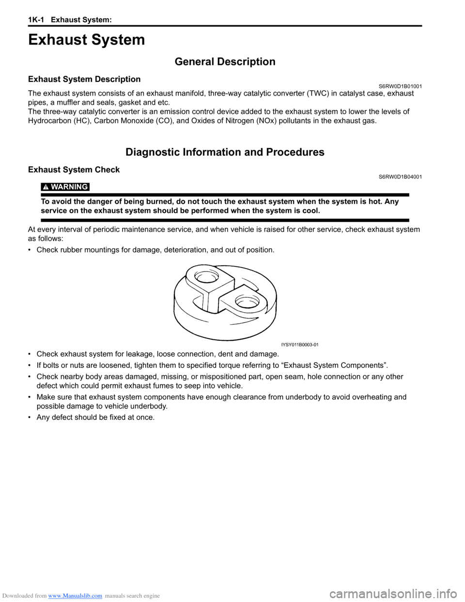
• Check rubber mountings for damage, deterioration, and out of position.
• Check exhaust system for leakage, loose connection, dent and damage.
• If bolts or nuts are loosened, tighten them to specified torque referring to “Exhaust System Components”.
• Check nearby body areas damaged, missing, or mispositioned part, open seam, hole connection or any other
defect which could permit exhaust fumes to seep into vehicle.
• Make sure that exhaust system components have enough clearance from underbody to avoid overheating and
possible damage to vehicle underbody.
• Any defect should be fixed at once.
IYSY011B0003-01
Page 430 of 1556

Downloaded from www.Manualslib.com manuals search engine 1K-3 Exhaust System:
Exhaust Manifold Removal and InstallationS6RW0D1B06002
Removal
WARNING!
To avoid danger of being burned, do not
service exhaust system while it is still hot.
Service should be performed after system
cools down.
1) Disconnect negative cable at battery.
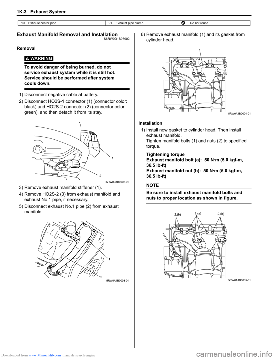
2) Disconnect HO2S-1 connector (1) (connector color:
black) and HO2S-2 connector (2) (connector color:
green), and then detach it from its stay.
3) Remove exhaust manifold stiffener (1).
4) Remove HO2S-2 (3) from exhaust manifold and
exhaust No.1 pipe, if necessary.
5) Disconnect exhaust No.1 pipe (2) from exhaust
manifold.6) Remove exhaust manifold (1) and its gasket from
cylinder head.
Installation
1) Install new gasket to cylinder head. Then install
exhaust manifold.
Tighten manifold bolts (1) and nuts (2) to specified
torque.
Tightening torque
Exhaust manifold bolt (a): 50 N·m (5.0 kgf-m,
36.5 lb-ft)
Exhaust manifold nut (b): 50 N·m (5.0 kgf-m,
36.5 lb-ft)
NOTE
Be sure to install exhaust manifold bolts and
nuts to proper location as shown in figure.
10. Exhaust center pipe 21. Exhaust pipe clamp : Do not reuse.
2
1
I5RW0C1B0002-01
2 3
1
I5RW0A1B0003-01
1
I5RW0A1B0004-01
1,(a)2,(b)2,(b)
I5RW0A1B0005-01