2006 SUZUKI SX4 Rear sensor
[x] Cancel search: Rear sensorPage 925 of 1556

Downloaded from www.Manualslib.com manuals search engine Table of Contents 7- i
7
Section 7
CONTENTS
HVAC
Precautions ................................................. 7-1
Precautions............................................................. 7-1
Precautions on HVAC ........................................... 7-1
Heater and Ventilation............................. 7A-1
General Description ............................................. 7A-1
Heater and Ventilation Construction ................... 7A-1
Schematic and Routing Diagram ........................ 7A-2
Heater and Ventilation Wiring Circuit Diagram .... 7A-2
Component Location ........................................... 7A-2
Electronic Control System Components
Location ............................................................ 7A-2
Diagnostic Information and Procedures ............ 7A-3
Heater and Ventilation Symptom Diagnosis........ 7A-3
Repair Instructions .............................................. 7A-4
HVAC Unit Components ..................................... 7A-4
HVAC Unit Removal and Installation (Non-A/
C) ...................................................................... 7A-4
Blower Motor Removal and Installation............... 7A-4
Blower Motor Inspection ..................................... 7A-4
Blower Motor Resistor Removal and
Installation ......................................................... 7A-5
Blower Motor Resistor Inspection ....................... 7A-5
Blower Motor Relay Inspection ........................... 7A-6
HVAC Control Unit Components ......................... 7A-6
HVAC Control Unit Removal and Installation ...... 7A-7
Blower Speed Selector Inspection ...................... 7A-9
Air Intake Selector Inspection ............................. 7A-9
Air Intake Control Actuator Removal and
Installation ......................................................... 7A-9
Air Intake Control Actuator Inspection .............. 7A-10
Center Ventilation Louver Removal and
Installation ....................................................... 7A-11
Side Ventilation Louver Removal and
Installation ....................................................... 7A-11
Rear Duct Removal and Installation (If
Equipped)........................................................ 7A-12
HVAC Air Filter Removal and Installation (If
Equipped)........................................................ 7A-12
HVAC Air Filter Inspection (If Equipped) ........... 7A-12
Air Conditioning System......................... 7B-1
Manual Type ............................................................ 7B-1
Precautions........................................................... 7B-1A/C System Caution ............................................ 7B-1
Precautions on Servicing A/C System ................ 7B-1
General Description .............................................7B-2
Sub-Cool A/C System Description ...................... 7B-2
Manual A/C Electronic Input Output Table .......... 7B-3
A/C Operation Description at ECM ..................... 7B-3
Schematic and Routing Diagram ........................7B-4
A/C System Air Flow Diagram............................. 7B-4
A/C System Wiring Diagram ............................... 7B-5
Component Location ...........................................7B-6
A/C System Major Components Location ........... 7B-6
Electronic Control System Components
Location............................................................. 7B-7
Diagnostic Information and Procedures ............7B-8
A/C System Performance Inspection .................. 7B-8
Trouble Diagnosis for Abnormal Pressure ........ 7B-11
A/C System Inspection at ECM ......................... 7B-12
A/C System Symptom Diagnosis ...................... 7B-13
Abnormal Noise Symptom Diagnosis of A/C
System ............................................................ 7B-15
Repair Instructions ............................................7B-17
Operation Procedure for Refrigerant Charge .... 7B-17
Condenser Cooling Fan Removal and
Installation ....................................................... 7B-22
Condenser Cooling Fan Inspection ................... 7B-23
Condenser Assembly On-Vehicle Inspection .... 7B-23
Condenser Assembly Removal and
Installation ....................................................... 7B-23
Desiccant Removal and Installation .................. 7B-24
HVAC Unit Components ................................... 7B-25
HVAC Unit Removal and Installation ................ 7B-26
Evaporator Inspection ....................................... 7B-27
Evaporator Temperature Sensor Removal
and Installation ................................................ 7B-27
Evaporator Temperature Sensor Inspection ..... 7B-28
Expansion Valve Removal and Installation ....... 7B-28
Expansion Valve Inspection .............................. 7B-28
A/C Refrigerant Pressure Sensor and Its
Circuit Inspection............................................. 7B-29
A/C Refrigerant Pressure Sensor Removal
and Installation ................................................ 7B-29
A/C Switch Inspection ....................................... 7B-29
A/C System Relay Inspection............................ 7B-30
Compressor Drive Belt Inspection and
Adjustment ...................................................... 7B-30
Page 945 of 1556
![SUZUKI SX4 2006 1.G Service Workshop Manual Downloaded from www.Manualslib.com manuals search engine Air Conditioning System: Manual Type 7B-5
A/C System Wiring DiagramS6RW0D7212002
[A]
7
WHT
GRN5YELBLK
3
G154-3
G154-4
G154-7
G154-8
G154-10
G15 SUZUKI SX4 2006 1.G Service Workshop Manual Downloaded from www.Manualslib.com manuals search engine Air Conditioning System: Manual Type 7B-5
A/C System Wiring DiagramS6RW0D7212002
[A]
7
WHT
GRN5YELBLK
3
G154-3
G154-4
G154-7
G154-8
G154-10
G15](/manual-img/20/7612/w960_7612-944.png)
Downloaded from www.Manualslib.com manuals search engine Air Conditioning System: Manual Type 7B-5
A/C System Wiring DiagramS6RW0D7212002
[A]
7
WHT
GRN5YELBLK
3
G154-3
G154-4
G154-7
G154-8
G154-10
G154-13
G154-5
G154-6
G155-5
G155-2
G155-3
G155-7
G155-6
G155-1
G154-9
G154-14
BLK/WHT
YEL
BLU/WHT
RED
BRN
GRN/WHT
RED/BLK
RED
GRN
GRN/YEL
RED/YEL
RED/BLU
20
21
23 22
BLK/RED
6 2
MBLK/WHTBLK/YEL
M
11
4RED/YEL 1
E01-49
12
E01-16
GRY 13
12V
BLU/WHTE01-3510
E01-48
18
19RED/BLK
BLK/RED
BLK/RED
BRN/WHTE01-60
E01-1
E01-29BLK/WHT
M
BLU/YELBLK/YEL
5V5V 5V
WHT/BLK
9
ORN
14E01-36
C01-12C01-14GRY/REDRED/BLU
E01-41
RED/BLK
RED
WHT
8
BLK
BLK/ORN
BLU IG1
IG2
5V
17
28
29
31
2726 2524
16
16
30
34
33E01-4 E01-19WHTRED
C01-50C01-49WHTRED
32
LT GRN
C01-57
C01-2415
GRY/BLU5V
I6RW0C721002-01
[A]: Illumination control model 9. A/C refrigerant pressure
sensor18. Condenser cooling fan relay 27. Illumination light
1. Ignition switch 10. ECM 19. Condenser cooling fan motor 28. Rear defogger relay
2. Blower motor 11. Air intake control actuator 20. Blower speed selector 29. Rear defogger
3. HVAC control unit 12. Compressor relay 21. A/C switch 30. Main relay
4. Lighting switch 13. Compressor 22. Air intake selector 31. Tail light
5. Blower motor relay 14. Evaporator temperature
sensor23. Rear defogger switch 32. TCM
6. Blower motor resistor 15. ECT sensor 24. “A/C” indicator light 33. To other control module and DLC
7. Junction block assembly 16. To BCM 25. “REC” indicator light 34. ABS control module
8. BCM 17. Main fuse box 26. Rear defogger indicator
Page 947 of 1556

Downloaded from www.Manualslib.com manuals search engine Air Conditioning System: Manual Type 7B-7
Electronic Control System Components LocationS6RW0D7213002
NOTE
The figure shows left-hand steering vehicle. For right-hand steering vehicle, parts with (*) are installed
at the opposite side.
[A]
8*
9* 10*
11
1
5
7*
6
7*
12
13
14
1715
1642
3
I6RW0C721003-01
[A]: Junction block assembly viewed from relay side 6. Blower motor relay 12. Air intake selector
1. A/C refrigerant pressure sensor 7. Junction block assembly 13. Rear defogger switch
2. Compressor relay 8. Air intake actuator 14. Temperature selector
3. Condenser cooling fan relay 9. Blower motor 15. Blower speed selector
4. ECT sensor 10. Blower motor resistor 16. Air flow selector
5. Condenser cooling fan 11. HVAC control unit 17. A/C switch
Page 955 of 1556

Downloaded from www.Manualslib.com manuals search engine Air Conditioning System: Manual Type 7B-15
Abnormal Noise Symptom Diagnosis of A/C SystemS6RW0D7214005
Abnormal Noise from Compressor
Abnormal Noise from Magnetic ClutchInsufficient air flow of
cooled airA/C evaporator clogged or frostedCheck A/C evaporator and evaporator
temperature sensor referring to “Evaporator
Inspection” and “Evaporator Temperature
Sensor Inspection”.
Air leaking from HVAC unit or air ductRepair as necessary.
Blower motor faultyCheck blower motor referring to “Blower Motor
Inspection in Section 7A”.
Wiring or grounding faultyRepair as necessary. Condition Possible cause Correction / Reference Item
Condition Possible cause Correction / Reference Item
During compressor
operation, a rumbling
noise is heard
proportional to engine
revolutionsInadequate clearance in scroll areaReplace compressor.
A loud noise is heard at a
certain rpm,
disproportionately to
engine revolutionLoose or faulty compressor drive beltAdjust drive belt tension or replace drive belt.
Loose compressor mounting boltsRetighten mounting bolts.
A loud rattle is heard at
low engine rpmLoose compressor clutch plate boltRetighten clutch plate bolt.
Replace compressor if it was operated in this
condition for a long time.
Condition Possible cause Correction / Reference Item
A rumbling noise is heard
when compressor is not
in operationWorn or damaged bearingsReplace magnet clutch assembly.
A chattering noise is
heard when compressor
is in operationFaulty magnet clutch clearance
(excessive clearance)Adjust magnet clutch clearance.
Worn magnet clutch friction surfaceReplace magnet clutch assembly.
Compressor oil leaked from shaft seal,
contaminating the friction surfaceReplace compressor body assembly.
Page 983 of 1556

Downloaded from www.Manualslib.com manuals search engine Air Conditioning System: Automatic Type 7B-43
Component Location
A/C System Major Components LocationS6RW0D7223001
Refer to “A/C System Major Components Location”.
[A]: Illumination control model 10. Air intake actuator 22. Compressor 34. “A/C” indicator light
[B]: Junction block with BCM 11. Air flow control actuator 23. HVAC control module 35. Rear defogger switch
[C]: Junction block without BCM 12. Temperature control actuator 24. BCM 36. Rear defogger indicator
1. Main fuse box 13. Inside air temperature sensor 25. A/C refrigerant pressure sensor 37. To other control module
2. Ignition switch 14. Outside air temperature sensor 26. Condenser cooling fan relay 38. Indicator light, switch,
selector
3. CAN junction connector 15. Evaporator temperature sensor 27. Information display 39. “FRE” indicator light
4. Rear defogger relay 16. Sunload sensor 28. Lighting switch 40. “REC” indicator light
5. Rear defogger 17. Junction block assembly 29. A/C switch 41. Temperature selector
6. Blower motor relay 18. ECM 30. Air intake selector 42. Blower speed selector
7. Blower motor 19. ECT sensor 31. To BCM 43. MODE (air flow) selector
8. Blower motor controller 20. Condenser cooling fan motor 32. ABS control module 44. Tail light
9. DLC 21. Compressor relay 33. Illumination light 45. Main relay
Page 984 of 1556

Downloaded from www.Manualslib.com manuals search engine 7B-44 Air Conditioning System: Automatic Type
Electronic Control System Components LocationS6RW0D7223002
NOTE
The figure shows left-hand steering vehicle. For right-hand steering vehicle, parts with (*) are installed
at the opposite side.
[A]
2
3
5
1
4
78*
18
19
20
23
22 219*
10*
11*
12*
13*
15* 16* 17
14*
8*6
I6RW0C722003-01
[A]: Junction block assembly viewed from relay
side8. Junction block assembly 16. Blower motor controller
1. A/C refrigerant pressure sensor 9. Sunload sensor 17. HVAC control module
2. Compressor relay 10. Inside air temperature sensor 18. Temperature selector
3. Condenser cooling fan relay 11. Air flow control actuator 19. Blower speed selector
4. Outside air temperature sensor 12. Temperature control actuator 20. MODE (air flow) selector
5. ECT sensor 13. Evaporator temperature sensor 21. A/C switch
6. Condenser cooling fan 14. Air intake actuator 22. Air intake selector
7. Blower motor relay 15. Blower motor 23. Rear defogger switch
Page 1018 of 1556

Downloaded from www.Manualslib.com manuals search engine 7B-78 Air Conditioning System: Automatic Type
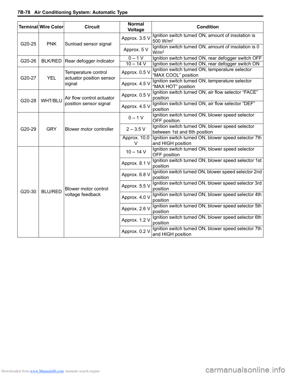
G20-25 PNK Sunload sensor signalApprox. 3.5 VIgnition switch turned ON, amount of insolation is
500 W/m2
Approx. 5 VIgnition switch turned ON, amount of insolation is 0
W/m2
G20-26 BLK/RED Rear defogger indicator0 – 1 V Ignition switch turned ON, rear defogger switch OFF
10 – 14 V Ignition switch turned ON, rear defogger switch ON
G20-27 YELTemperature control
actuator position sensor
signalApprox. 0.5 VIgnition switch turned ON, temperature selector
“MAX COOL” position
Approx. 4.5 VIgnition switch turned ON, temperature selector
“MAX HOT” position
G20-28 WHT/BLUAir flow control actuator
position sensor signalApprox. 0.5 VIgnition switch turned ON, air flow selector “FACE”
position
Approx. 4.5 VIgnition switch turned ON, air flow selector “DEF”
position
G20-29 GRY Blower motor controller0 – 1 VIgnition switch turned ON, blower speed selector
OFF position
2 – 3.5 VIgnition switch turned ON, blower speed selector
between 1st and 6th position
Approx. 10.0
VIgnition switch turned ON, blower speed selector 7th
and HIGH position
G20-30 BLU/REDBlower motor control
voltage feedback10 – 14 VIgnition switch turned ON, blower speed selector
OFF position
Approx. 8.1 VIgnition switch turned ON, blower speed selector 1st
position
Approx. 6.8 VIgnition switch turned ON, blower speed selector 2nd
position
Approx. 5.5 VIgnition switch turned ON, blower speed selector 3rd
position
Approx. 4.0 VIgnition switch turned ON, blower speed selector 4th
position
Approx. 2.6 VIgnition switch turned ON, blower speed selector 5th
position
Approx. 1.2 VIgnition switch turned ON, blower speed selector 6th
position
Approx. 0.2 VIgnition switch turned ON, blower speed selector 7th
and HIGH position Terminal Wire Color CircuitNormal
Vo l ta g eCondition
Page 1045 of 1556

Downloaded from www.Manualslib.com manuals search engine Air Bag System: 8B-6
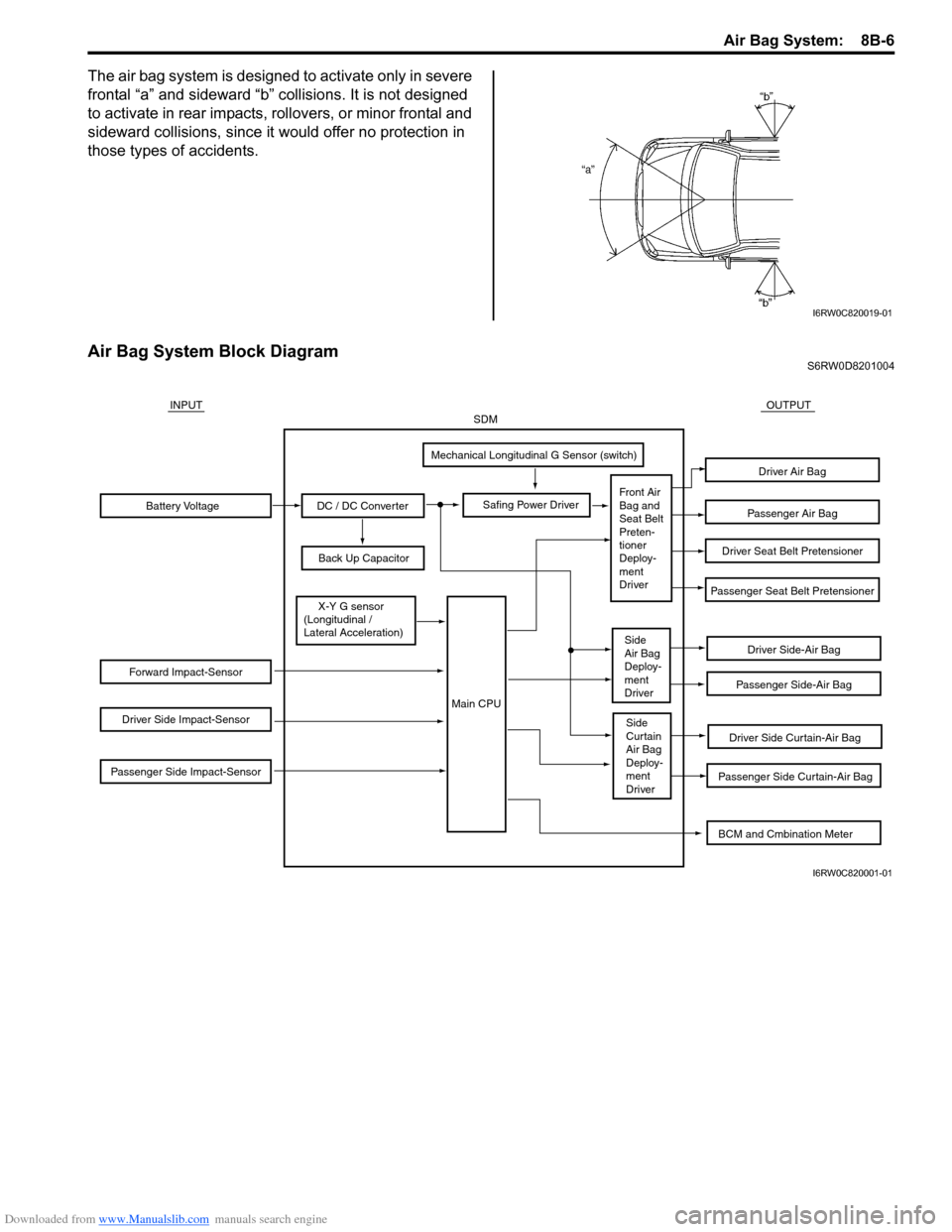
The air bag system is designed to activate only in severe
frontal “a” and sideward “b” collisions. It is not designed
to activate in rear impacts, rollovers, or minor frontal and
sideward collisions, since it would offer no protection in
those types of accidents.
Air Bag System Block DiagramS6RW0D8201004
I6RW0C820019-01
Battery Voltage
Forward Impact-Sensor
Driver Side Impact-Sensor
Passenger Side Impact-Sensor
DC / DC Converter
Back Up Capacitor
Safing Power Driver
Mechanical Longitudinal G Sensor (switch)
X-Y G sensor
(Longitudinal /
Lateral Acceleration)
Driver Side-Air Bag
Driver Side Curtain-Air Bag
Passenger Side Curtain-Air Bag
Passenger Side-Air Bag
Passenger Seat Belt Pretensioner
Driver Seat Belt Pretensioner
Passenger Air Bag
Driver Air Bag
INPUTOUTPUTSDM
Front Air
Bag and
Seat Belt
Preten-
tioner
Deploy-
ment
Driver
Side
Air Bag
Deploy-
ment
Driver
Side
Curtain
Air Bag
Deploy-
ment
Driver
Main CPU
BCM and Cmbination Meter
I6RW0C820001-01