2006 SUZUKI SX4 terminal
[x] Cancel search: terminalPage 1520 of 1556
Downloaded from www.Manualslib.com manuals search engine 10C-18 Immobilizer Control System:
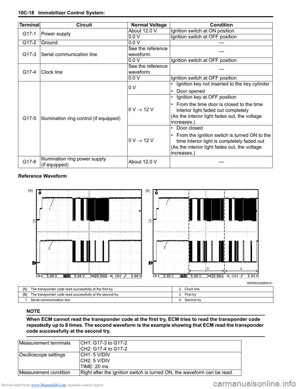
Reference Waveform
NOTE
When ECM cannot read the transponder code at the first try, ECM tries to read the transponder code
repeatedly up to 8 times. The second waveform is the example showing that ECM read the transponder
code successfully at the second try.
Terminal Circuit Normal Voltage Condition
G17-1 Power supplyAbout 12.0 V Ignition switch at ON position
0.0 V Ignition switch at OFF position
G17-2 Ground 0.0 V —
G17-3 Serial communication lineSee the reference
waveform.—
0.0 V Ignition switch at OFF position
G17-4 Clock lineSee the reference
waveform.—
0.0 V Ignition switch at OFF position
G17-5 Illumination ring control (if equipped)0 V• Ignition key not inserted to the key cylinder
• Door opened
0 V → 12 V• Ignition key at OFF position
• From the time door is closed to the time
interior light faded out completely
(As the interior light fades out, the voltage
increases.)
0 V → 12 V• Door closed
• From the ignition switch is turned ON to the
time interior light is completely faded out
(As the interior light fades out, the voltage
increases.)
G17-6Illumination ring power supply
(if equipped)About 12.0 V —
I6RW0CA30003-01
[A]: The transponder code read successfully at the first try. 2. Clock line
[B]: The transponder code read successfully at the second try. 3. First try
1. Serial communication line 4. Second try
Measurement terminals CH1: G17-3 to G17-2
CH2: G17-4 to G17-2
Oscilloscope settings CH1: 5 V/DIV
CH2: 5 V/DIV
TIME: 20 ms
Measurement condition Right after the ignition switch is turned ON, the waveform can be read.
Page 1537 of 1556
Downloaded from www.Manualslib.com manuals search engine Keyless Start System: 10E-15
Voltage Check
1) Disconnect negative cable (–) at battery.
2) Remove keyless start control module from vehicle body referring to “Keyless Start Control Module Removal and
Installation”.
3) Connect connector to keyless start control module.
4) Check voltage at each terminal number of couplers connected.
NOTE
• As each terminal voltage is affected by the battery voltage, confirm that it is 11 V or more when
ignition switch is ON.
• Voltage with asterisk (*) cannot be measured by voltmeter because it is pulse signal.
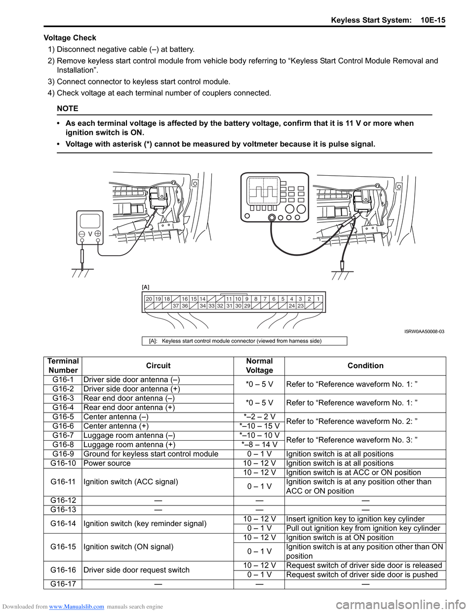
1 2 3 4 5 6 7 8 9 10 11 14 15 16
36 34 33 32 31 30 29 24 23 37 18 19 20
[A]
I5RW0AA50008-03
[A]: Keyless start control module connector (viewed from harness side)
Terminal
NumberCircuitNormal
Vo l ta g eCondition
G16-1 Driver side door antenna (–)
*0 – 5 V Refer to “Reference waveform No. 1: ”
G16-2 Driver side door antenna (+)
G16-3 Rear end door antenna (–)
*0 – 5 V Refer to “Reference waveform No. 1: ”
G16-4 Rear end door antenna (+)
G16-5 Center antenna (–) *–2 – 2 V
Refer to “Reference waveform No. 2: ”
G16-6 Center antenna (+) *–10 – 15 V
G16-7 Luggage room antenna (–) *–10 – 10 V
Refer to “Reference waveform No. 3: ”
G16-8 Luggage room antenna (+) *–8 – 14 V
G16-9 Ground for keyless start control module 0 – 1 V Ignition switch is at all positions
G16-10 Power source 10 – 12 V Ignition switch is at all positions
G16-11 Ignition switch (ACC signal)10 – 12 V Ignition switch is at ACC or ON position
0 – 1 VIgnition switch is at any position other than
ACC or ON position
G16-12 — — —
G16-13 — — —
G16-14 Ignition switch (key reminder signal)10 – 12 V Insert ignition key to ignition key cylinder
0 – 1 V Pull out ignition key from ignition key cylinder
G16-15 Ignition switch (ON signal)10 – 12 V Ignition switch is at ON position
0 – 1 VIgnition switch is at any position other than ON
position
G16-16 Driver side door request switch10 – 12 V Request switch of driver side door is released
0 – 1 V Request switch of driver side door is pushed
G16-17 — — —
Page 1538 of 1556
Downloaded from www.Manualslib.com manuals search engine 10E-16 Keyless Start System:
G16-18 CAN communication line (low) *1.6 – 2.5 V
Refer to “Reference waveform No. 4: ”
G16-19 CAN communication line (high) *2.5 – 3.6 V
G16-20 Power supply for steering lock unit 4 – 6 V Full time
G16-21 — — —
G16-22 — — —
G16-23 Passenger side door antenna (–)
*0 – 5 V Refer to “Reference waveform No. 1: ”
G16-24 Passenger side door antenna (+)
G16-25 — — —
G16-26 — — —
G16-27 — — —
G16-28 — — —
G16-29 Signal for steering lock unit4 – 6 VIgnition knob switch is at any position other
than ON and OFF position
*0 – 5 V Refer to “Reference waveform No. 5: ”
G16-30 Ground for steering lock unit 0 – 1 V Full time
G16-31 — — —
G16-32 Rear end door request switch10 – 12 V Request switch of rear end door is released
0 – 1 V Request switch of rear end door is pushed
G16-33 Driver side door lock switch0 – 1 VDriver side door is at unlock position and
passenger side door is at lock position
4 – 6 VDriver and passenger side door is at lock
position
*3 – 5 V Refer to “Reference waveform No. 6: ”
G16-34 Ignition knob switch10 – 12 VWhen pushing ignition knob switch of steering
lock unit
0 – 1 VWhen releasing ignition knob switch of
steering lock unit
G16-35 — — —
G16-36 Passenger side door request switch10 – 12 VRequest switch of passenger side door is
released
0 – 1 VRequest switch of passenger side door is
pushed
G16-37 Passenger side door lock switch0 – 1 VPassenger side door is at unlock position and
driver side door is at lock position
4 – 6 VDriver and passenger side door is at lock
position
*3 – 5 V Refer to “Reference waveform No. 6: ”
G16-38 — — —
G16-39 — — —
G16-40 — — — Terminal
NumberCircuitNormal
Vo l ta g eCondition
Page 1539 of 1556
Downloaded from www.Manualslib.com manuals search engine Keyless Start System: 10E-17
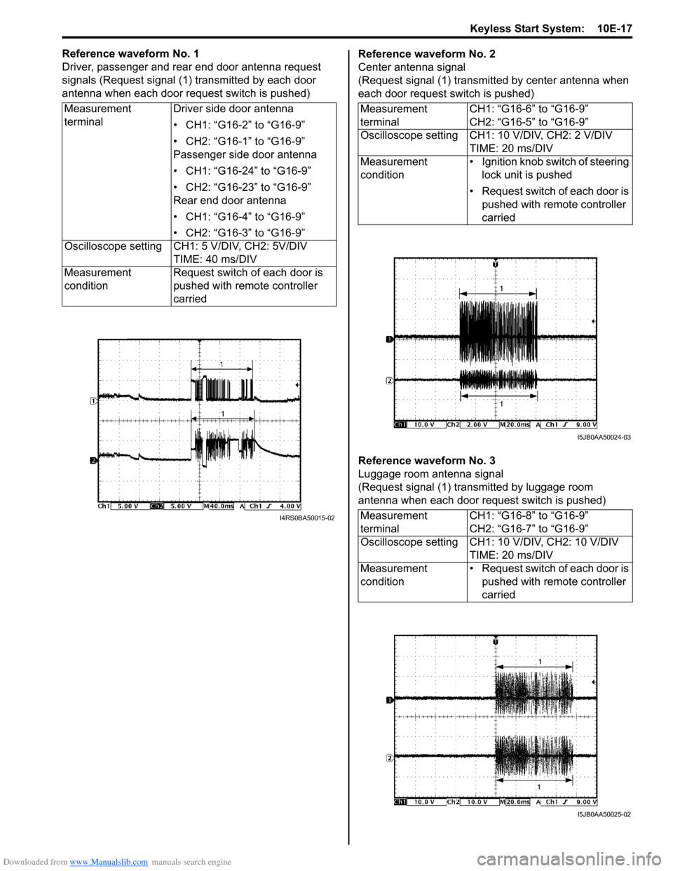
Reference waveform No. 1
Driver, passenger and rear end door antenna request
signals (Request signal (1) transmitted by each door
antenna when each door request switch is pushed)Reference waveform No. 2
Center antenna signal
(Request signal (1) transmitted by center antenna when
each door request switch is pushed)
Reference waveform No. 3
Luggage room antenna signal
(Request signal (1) transmitted by luggage room
antenna when each door request switch is pushed) Measurement
terminalDriver side door antenna
• CH1: “G16-2” to “G16-9”
• CH2: “G16-1” to “G16-9”
Passenger side door antenna
• CH1: “G16-24” to “G16-9”
• CH2: “G16-23” to “G16-9”
Rear end door antenna
• CH1: “G16-4” to “G16-9”
• CH2: “G16-3” to “G16-9”
Oscilloscope setting CH1: 5 V/DIV, CH2: 5V/DIV
TIME: 40 ms/DIV
Measurement
conditionRequest switch of each door is
pushed with remote controller
carried
I4RS0BA50015-02
Measurement
terminalCH1: “G16-6” to “G16-9”
CH2: “G16-5” to “G16-9”
Oscilloscope setting CH1: 10 V/DIV, CH2: 2 V/DIV
TIME: 20 ms/DIV
Measurement
condition• Ignition knob switch of steering
lock unit is pushed
• Request switch of each door is
pushed with remote controller
carried
Measurement
terminalCH1: “G16-8” to “G16-9”
CH2: “G16-7” to “G16-9”
Oscilloscope setting CH1: 10 V/DIV, CH2: 10 V/DIV
TIME: 20 ms/DIV
Measurement
condition• Request switch of each door is
pushed with remote controller
carried
I5JB0AA50024-03
I5JB0AA50025-02
Page 1540 of 1556
Downloaded from www.Manualslib.com manuals search engine 10E-18 Keyless Start System:
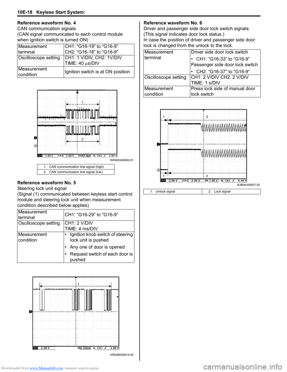
Reference waveform No. 4
CAN communication signals
(CAN signal communicated to each control module
when ignition switch is turned ON)
Reference waveform No. 5
Steering lock unit signal
(Signal (1) communicated between keyless start control
module and steering lock unit when measurement
condition described below applies)Reference waveform No. 6
Driver and passenger side door lock switch signals.
(This signal indicates door lock status.)
In case the position of driver and passenger side door
lock is changed from the unlock to the lock.
Measurement
terminalCH1: “G16-19” to “G16-9”
CH2: “G16-18” to “G16-9”
Oscilloscope setting CH1: 1 V/DIV, CH2: 1V/DIV
TIME: 40 µs/DIV
Measurement
conditionIgnition switch is at ON position
1. CAN communication line signal (high)
2. CAN communication line signal (low)
Measurement
terminalCH1: “G16-29” to “G16-9”
Oscilloscope setting CH1: 2 V/DIV
TIME: 4 ms/DIV
Measurement
condition• Ignition knob switch of steering
lock unit is pushed
• Any one of door is opened
• Request switch of each door is
pushed
I5RS0DA50002-01
I4RS0BA50019-02
Measurement
terminalDriver side door lock switch
• CH1: “G16-33” to “G16-9”
Passenger side door lock switch
• CH2: “G16-37” to “G16-9”
Oscilloscope setting CH1: 2 V/DIV CH2: 2 V/DIV
TIME: 1 s/DIV
Measurement
conditionPress lock side of manual door
lock switch
1. Unlock signal 2. Lock signal
I5JB0AA50027-02
Page 1541 of 1556
Downloaded from www.Manualslib.com manuals search engine Keyless Start System: 10E-19
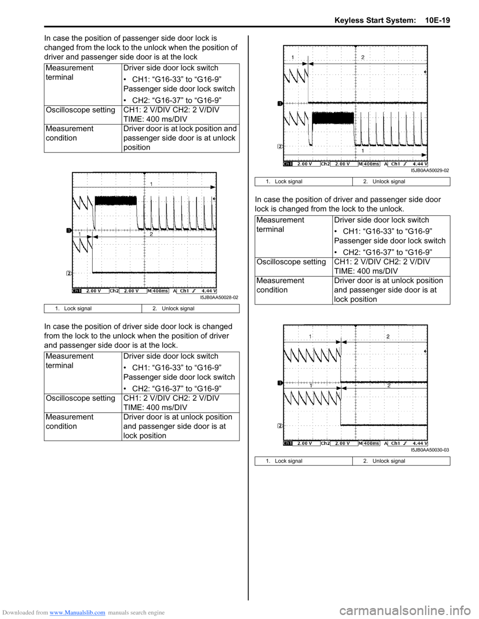
In case the position of passenger side door lock is
changed from the lock to the unlock when the position of
driver and passenger side door is at the lock
In case the position of driver side door lock is changed
from the lock to the unlock when the position of driver
and passenger side door is at the lock.In case the position of driver and passenger side door
lock is changed from the lock to the unlock. Measurement
terminalDriver side door lock switch
• CH1: “G16-33” to “G16-9”
Passenger side door lock switch
• CH2: “G16-37” to “G16-9”
Oscilloscope setting CH1: 2 V/DIV CH2: 2 V/DIV
TIME: 400 ms/DIV
Measurement
conditionDriver door is at lock position and
passenger side door is at unlock
position
1. Lock signal 2. Unlock signal
Measurement
terminalDriver side door lock switch
• CH1: “G16-33” to “G16-9”
Passenger side door lock switch
• CH2: “G16-37” to “G16-9”
Oscilloscope setting CH1: 2 V/DIV CH2: 2 V/DIV
TIME: 400 ms/DIV
Measurement
conditionDriver door is at unlock position
and passenger side door is at
lock position
I5JB0AA50028-02
1. Lock signal 2. Unlock signal
Measurement
terminalDriver side door lock switch
• CH1: “G16-33” to “G16-9”
Passenger side door lock switch
• CH2: “G16-37” to “G16-9”
Oscilloscope setting CH1: 2 V/DIV CH2: 2 V/DIV
TIME: 400 ms/DIV
Measurement
conditionDriver door is at unlock position
and passenger side door is at
lock position
1. Lock signal 2. Unlock signal
I5JB0AA50029-02
I5JB0AA50030-03
Page 1545 of 1556
Downloaded from www.Manualslib.com manuals search engine Keyless Start System: 10E-23
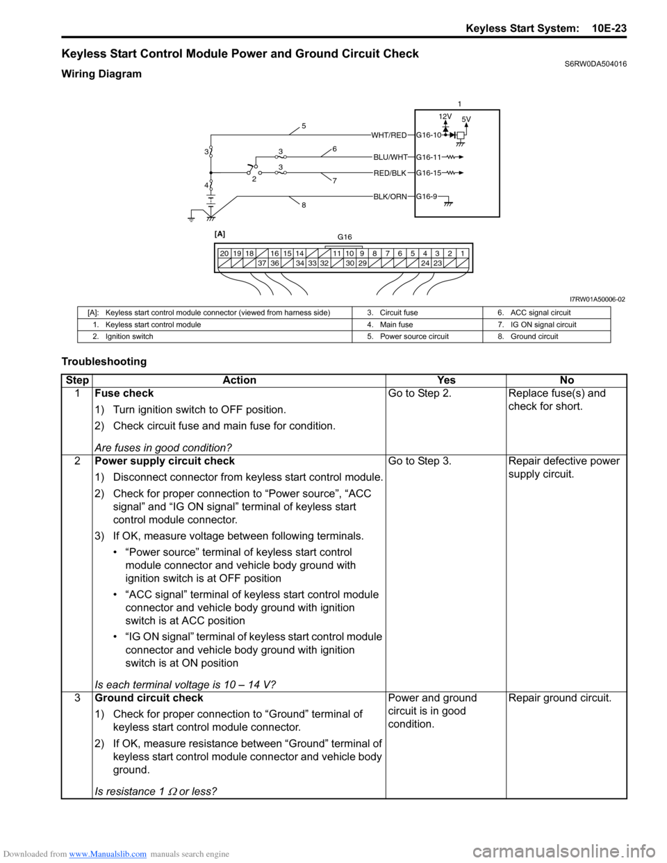
Keyless Start Control Module Power and Ground Circuit CheckS6RW0DA504016
Wiring Diagram
Troubleshooting
BLK/ORNG16-9
G16-15
G16-10
G16-11BLU/WHT
WHT/RED
RED/BLK
5V 12V
1 2 3 4 5 6 7 8 9 10 11 14 15 16
36 34 33 32 30 29 24 23 37 18 19 20
[A] 423
31
G16 5
86
7
3
I7RW01A50006-02
[A]: Keyless start control module connector (viewed from harness side) 3. Circuit fuse 6. ACC signal circuit
1. Keyless start control module 4. Main fuse 7. IG ON signal circuit
2. Ignition switch 5. Power source circuit 8. Ground circuit
Step Action Yes No
1Fuse check
1) Turn ignition switch to OFF position.
2) Check circuit fuse and main fuse for condition.
Are fuses in good condition?Go to Step 2. Replace fuse(s) and
check for short.
2Power supply circuit check
1) Disconnect connector from keyless start control module.
2) Check for proper connection to “Power source”, “ACC
signal” and “IG ON signal” terminal of keyless start
control module connector.
3) If OK, measure voltage between following terminals.
• “Power source” terminal of keyless start control
module connector and vehicle body ground with
ignition switch is at OFF position
• “ACC signal” terminal of keyless start control module
connector and vehicle body ground with ignition
switch is at ACC position
• “IG ON signal” terminal of keyless start control module
connector and vehicle body ground with ignition
switch is at ON position
Is each terminal voltage is 10 – 14 V?Go to Step 3. Repair defective power
supply circuit.
3Ground circuit check
1) Check for proper connection to “Ground” terminal of
keyless start control module connector.
2) If OK, measure resistance between “Ground” terminal of
keyless start control module connector and vehicle body
ground.
Is resistance 1
Ω or less?Power and ground
circuit is in good
condition.Repair ground circuit.
Page 1546 of 1556
Downloaded from www.Manualslib.com manuals search engine 10E-24 Keyless Start System:
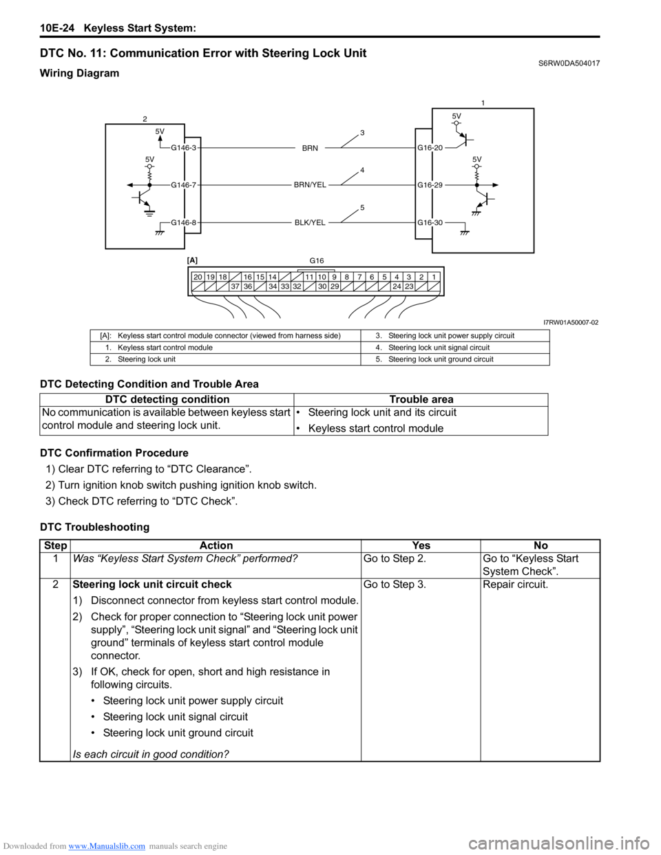
DTC No. 11: Communication Error with Steering Lock UnitS6RW0DA504017
Wiring Diagram
DTC Detecting Condition and Trouble Area
DTC Confirmation Procedure
1) Clear DTC referring to “DTC Clearance”.
2) Turn ignition knob switch pushing ignition knob switch.
3) Check DTC referring to “DTC Check”.
DTC Troubleshooting
5V
G16-20
G16-29
G16-30
G146-3
G146-7
G146-8
1 2 3 4 5 6 7 8 9 10 11 14 15 16
36 34 33 32 30 29 24 23 37 18 19 20
5V
5V
BRN
BRN/YEL
BLK/YEL
5V
21
[A]
G16
3
4
5
I7RW01A50007-02
[A]: Keyless start control module connector (viewed from harness side) 3. Steering lock unit power supply circuit
1. Keyless start control module 4. Steering lock unit signal circuit
2. Steering lock unit 5. Steering lock unit ground circuit
DTC detecting condition Trouble area
No communication is available between keyless start
control module and steering lock unit.• Steering lock unit and its circuit
• Keyless start control module
Step Action Yes No
1Was “Keyless Start System Check” performed?Go to Step 2. Go to “Keyless Start
System Check”.
2Steering lock unit circuit check
1) Disconnect connector from keyless start control module.
2) Check for proper connection to “Steering lock unit power
supply”, “Steering lock unit signal” and “Steering lock unit
ground” terminals of keyless start control module
connector.
3) If OK, check for open, short and high resistance in
following circuits.
• Steering lock unit power supply circuit
• Steering lock unit signal circuit
• Steering lock unit ground circuit
Is each circuit in good condition?Go to Step 3. Repair circuit.