2006 SUZUKI SX4 terminal
[x] Cancel search: terminalPage 1489 of 1556
Downloaded from www.Manualslib.com manuals search engine Body Electrical Control System: 10B-16
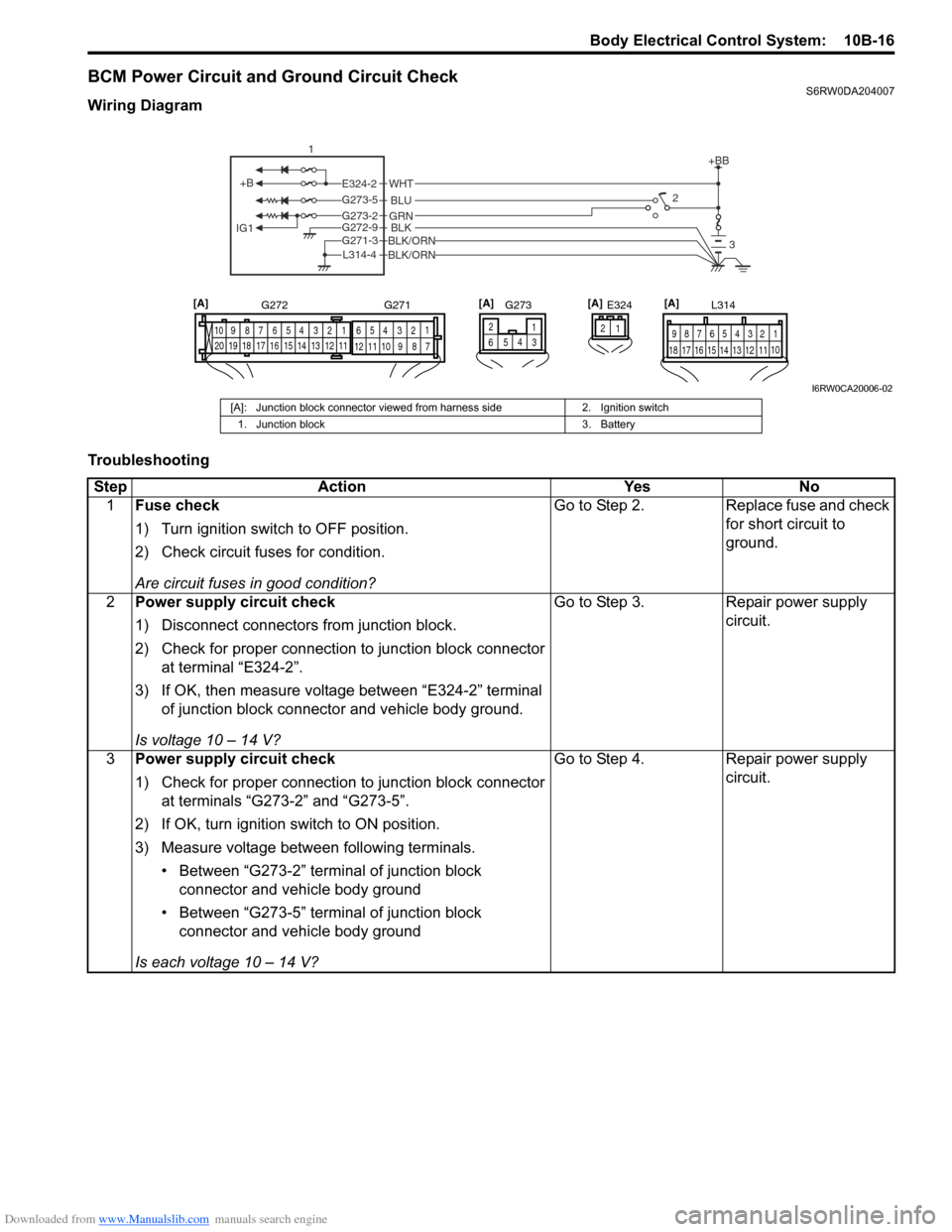
BCM Power Circuit and Ground Circuit CheckS6RW0DA204007
Wiring Diagram
Troubleshooting
+B
IG1
+BB
GRNG273-2BLKBLK/ORNG272-9
G271-3
BLK/ORNL314-4
BLU G273-5
WHTE324-22
3
1
E324 L314
1 2 4 53 6 7 8 9
10
11 12 13 14 15 16 17 181 21 2 4 53 61
2 4 53 6 7 8 9 10
7 8 9 10 11 12
11 12 13 14 15 16 17 18 19 20
G272 G271
1 2
4
65
G273[A] [A] [A]
3
[A]
I6RW0CA20006-02
[A]: Junction block connector viewed from harness side 2. Ignition switch
1. Junction block 3. Battery
Step Action Yes No
1Fuse check
1) Turn ignition switch to OFF position.
2) Check circuit fuses for condition.
Are circuit fuses in good condition?Go to Step 2. Replace fuse and check
for short circuit to
ground.
2Power supply circuit check
1) Disconnect connectors from junction block.
2) Check for proper connection to junction block connector
at terminal “E324-2”.
3) If OK, then measure voltage between “E324-2” terminal
of junction block connector and vehicle body ground.
Is voltage 10 – 14 V?Go to Step 3. Repair power supply
circuit.
3Power supply circuit check
1) Check for proper connection to junction block connector
at terminals “G273-2” and “G273-5”.
2) If OK, turn ignition switch to ON position.
3) Measure voltage between following terminals.
• Between “G273-2” terminal of junction block
connector and vehicle body ground
• Between “G273-5” terminal of junction block
connector and vehicle body ground
Is each voltage 10 – 14 V?Go to Step 4. Repair power supply
circuit.
Page 1490 of 1556
Downloaded from www.Manualslib.com manuals search engine 10B-17 Body Electrical Control System:
DTC B1133 (DTC No. 1133): Battery Voltage Too HighS6RW0DA204008
Wiring Diagram
Refer to “BCM Power Circuit and Ground Circuit Check”.
DTC Detecting Condition and Possible Cause
Flow Test Description
Step 1: Check charging system
DTC Troubleshooting4Ground circuit check
1) Turn ignition switch to OFF position.
2) Check for proper connection to junction block connector
at terminals “G271-3”, “G272-9” and “L314-4”.
3) If OK, then measure resistance between following
terminals.
• Between “G271-3” terminal of junction block
connector and vehicle body ground
• Between “G272-9” terminal of junction block
connector and vehicle body ground
• Between “L314-4” terminal of junction block connector
and vehicle body ground
Is each resistance 2
Ω or less?BCM power supply
circuit and ground circuit
are in good condition.Repair ground circuit. Step Action Yes No
DTC detecting condition Possible cause
Power voltage supplied from battery to BCM is
higher than 16V.• Charging system malfunction
• BCM malfunction
Step Action Yes No
1Charging system operation check
1) Check generator for operation referring to “Generator
Test (Overcharged Battery Check) in Section 1J”.
Is it in good condition?Substitute a known
good BCM (included in
junction block) and
recheck.Repair charging system.
Page 1491 of 1556
Downloaded from www.Manualslib.com manuals search engine Body Electrical Control System: 10B-18
DTC B1141 / DTC B1142 (No. 1141 / No. 1142) Outside Air Temperature (Ambient Temp.) Sensor
Circuit Malfunction
S6RW0DA204009
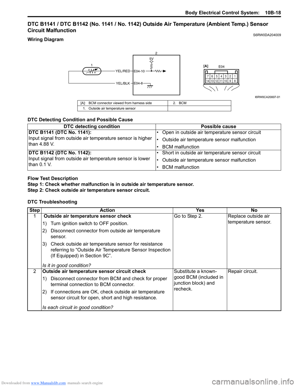
Wiring Diagram
DTC Detecting Condition and Possible Cause
Flow Test Description
Step 1: Check whether malfunction is in outside air temperature sensor.
Step 2: Check outside air temperature sensor circuit.
DTC Troubleshooting
YEL/RED
YEL/BLK
5V
E04-10
E04-8
12E04
1 2 4 53 6 7
8 9 10 11 12 13 14
[A]
I6RW0CA20007-01
[A]: BCM connector viewed from harness side 2. BCM
1. Outside air temperature sensor
DTC detecting condition Possible cause
DTC B1141 (DTC No. 1141):
Input signal from outside air temperature sensor is higher
than 4.88 V.• Open in outside air temperature sensor circuit
• Outside air temperature sensor malfunction
• BCM malfunction
DTC B1142 (DTC No. 1142):
Input signal from outside air temperature sensor is lower
than 0.1 V.• Short in outside air temperature sensor circuit
• Outside air temperature sensor malfunction
• BCM malfunction
Step Action Yes No
1 Outside air temperature sensor check
1) Turn ignition switch to OFF position.
2) Disconnect connector from outside air temperature
sensor.
3) Check outside air temperature sensor for resistance
referring to “Outside Air Temperature Sensor Inspection
(If Equipped) in Section 9C”.
Is it in good condition?Go to Step 2. Replace outside air
temperature sensor.
2Outside air temperature sensor circuit check
1) Disconnect connector from BCM and check for proper
terminal connection to BCM connector.
2) If connections are OK, check outside air temperature
sensor circuit for open, short and high resistance.
Is each circuit in good condition?Substitute a known-
good BCM (included in
junction block) and
recheck.Repair circuit.
Page 1492 of 1556
Downloaded from www.Manualslib.com manuals search engine 10B-19 Body Electrical Control System:
DTC B1150 (No. 1150): Air Bag Communication Circuit MalfunctionS6RW0DA204010
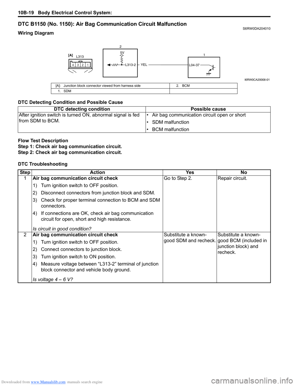
Wiring Diagram
DTC Detecting Condition and Possible Cause
Flow Test Description
Step 1: Check air bag communication circuit.
Step 2: Check air bag communication circuit.
DTC Troubleshooting
YEL
5V
L313-2L04-37
2
1
L313
1 2 43
[A]
I6RW0CA20008-01
[A]: Junction block connector viewed from harness side 2. BCM
1. SDM
DTC detecting condition Possible cause
After ignition switch is turned ON, abnormal signal is fed
from SDM to BCM.• Air bag communication circuit open or short
• SDM malfunction
• BCM malfunction
Step Action Yes No
1Air bag communication circuit check
1) Turn ignition switch to OFF position.
2) Disconnect connectors from junction block and SDM.
3) Check for proper terminal connection to BCM and SDM
connectors.
4) If connections are OK, check air bag communication
circuit for open, short and high resistance.
Is circuit in good condition?Go to Step 2. Repair circuit.
2Air bag communication circuit check
1) Turn ignition switch to OFF position.
2) Connect connectors to junction block.
3) Turn ignition switch to ON position.
4) Measure voltage between “L313-2” terminal of junction
block connector and vehicle body ground.
Is voltage 4 – 6 V?Substitute a known-
good SDM and recheck.Substitute a known-
good BCM (included in
junction block) and
recheck.
Page 1494 of 1556
Downloaded from www.Manualslib.com manuals search engine 10B-21 Body Electrical Control System:
Inspection of BCM and Its CircuitsS6RW0DA204017
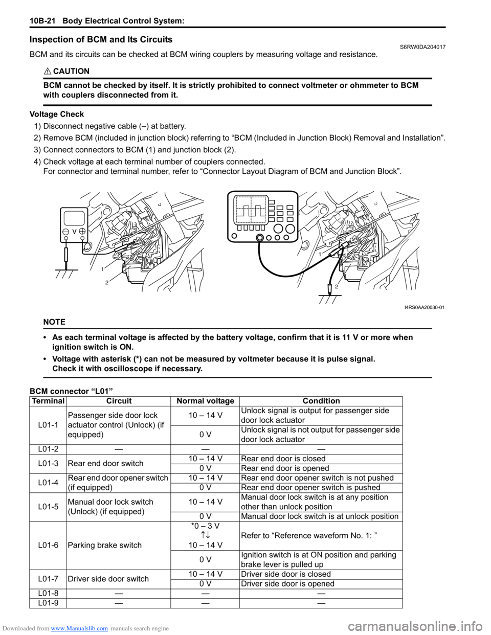
BCM and its circuits can be checked at BCM wiring couplers by measuring voltage and resistance.
CAUTION!
BCM cannot be checked by itself. It is strictly prohibited to connect voltmeter or ohmmeter to BCM
with couplers disconnected from it.
Voltage Check
1) Disconnect negative cable (–) at battery.
2) Remove BCM (included in junction block) referring to “BCM (Included in Junction Block) Removal and Installation”.
3) Connect connectors to BCM (1) and junction block (2).
4) Check voltage at each terminal number of couplers connected.
For connector and terminal number, refer to “Connector Layout Diagram of BCM and Junction Block”.
NOTE
• As each terminal voltage is affected by the battery voltage, confirm that it is 11 V or more when
ignition switch is ON.
• Voltage with asterisk (*) can not be measured by voltmeter because it is pulse signal.
Check it with oscilloscope if necessary.
BCM connector “L01”
1
2
1
2
I4RS0AA20030-01
Terminal Circuit Normal voltage Condition
L01-1Passenger side door lock
actuator control (Unlock) (if
equipped)10 – 14 VUnlock signal is output for passenger side
door lock actuator
0 VUnlock signal is not output for passenger side
door lock actuator
L01-2 — — —
L01-3 Rear end door switch10 – 14 V Rear end door is closed
0 V Rear end door is opened
L01-4Rear end door opener switch
(if equipped)10 – 14 V Rear end door opener switch is not pushed
0 V Rear end door opener switch is pushed
L01-5Manual door lock switch
(Unlock) (if equipped)10 – 14 VManual door lock switch is at any position
other than unlock position
0 V Manual door lock switch is at unlock position
L01-6 Parking brake switch*0 – 3 V
↑↓
10 – 14 VRefer to “Reference waveform No. 1: ”
0 VIgnition switch is at ON position and parking
brake lever is pulled up
L01-7 Driver side door switch10 – 14 V Driver side door is closed
0 V Driver side door is opened
L01-8 — — —
L01-9 — — —
Page 1495 of 1556
Downloaded from www.Manualslib.com manuals search engine Body Electrical Control System: 10B-22
BCM connector “E04”L01-10Driver side door lock
actuator control (Unlock) (if
equipped)10 – 14 VUnlock signal is output for driver side door
lock actuator
0 VUnlock signal is not output for driver side
door lock actuator
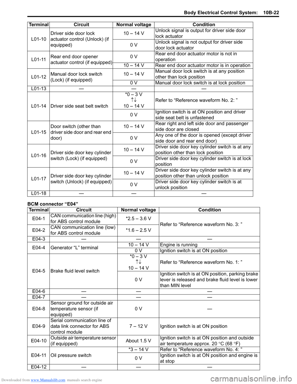
L01-11Rear end door opener
actuator control (if equipped)0 VRear end door actuator motor is not in
operation
10 – 14 V Rear end door actuator motor is in operation
L01-12Manual door lock switch
(Lock) (if equipped)10 – 14 VManual door lock switch is at any position
other than lock position
0 V Manual door lock switch is at lock position
L01-13 — — —
L01-14 Driver side seat belt switch*0 – 3 V
↑↓
10 – 14 VRefer to “Reference waveform No. 2: ”
0 VIgnition switch is at ON position and driver
side seat belt is unfastened
L01-15Door switch (other than
driver side door and rear end
door)10 – 14 VRear right and left side door and passenger
side door are closed
0 VAny one of the door is opened (except driver
side door and rear end door)
L01-16Driver side door key cylinder
switch (Lock) (if equipped)10 – 14 VDriver side door key cylinder switch is at any
position other than lock position
0 VDriver side door key cylinder switch is at lock
position
L01-17Driver side door key cylinder
switch (Unlock) (if equipped)10 – 14 VDriver side door key cylinder switch is at any
position other than unlock position
0 VDriver side door key cylinder switch is at
unlock position
L01-18 — — —
Terminal Circuit Normal voltage Condition
E04-1CAN communication line (high)
for ABS control module*2.5 – 3.6 V
Refer to “Reference waveform No. 3: ”
E04-2CAN communication line (low)
for ABS control module*1.6 – 2.5 V
E04-3 — — —
E04-4 Generator “L” terminal10 – 14 V Engine is running
0 V Ignition switch is at ON position
E04-5 Brake fluid level switch*0 – 3 V
↑↓
10 – 14 VRefer to “Reference waveform No. 1: ”
0 VIgnition switch is at ON position, parking brake
lever is released and brake fluid level is lower
than MIN level
E04-6 — — —
E04-7 — — —
E04-8Sensor ground for outside air
temperature sensor (if
equipped)0 V —
E04-9Serial communication line of
data link connector for ABS
control module7 – 12 V Ignition switch is at ON position
E04-10Outside air temperature sensor
(if equipped)About 1.5 VIgnition switch is at ON position and outside
air temperature approx. 20 °C (68
°F)
E04-11 Oil pressure switch*3 – 14 V Refer to “Reference waveform No. 4: ”
0 VIgnition switch is at ON position and engine is
at stop
E04-12 — — — Terminal Circuit Normal voltage Condition
Page 1496 of 1556
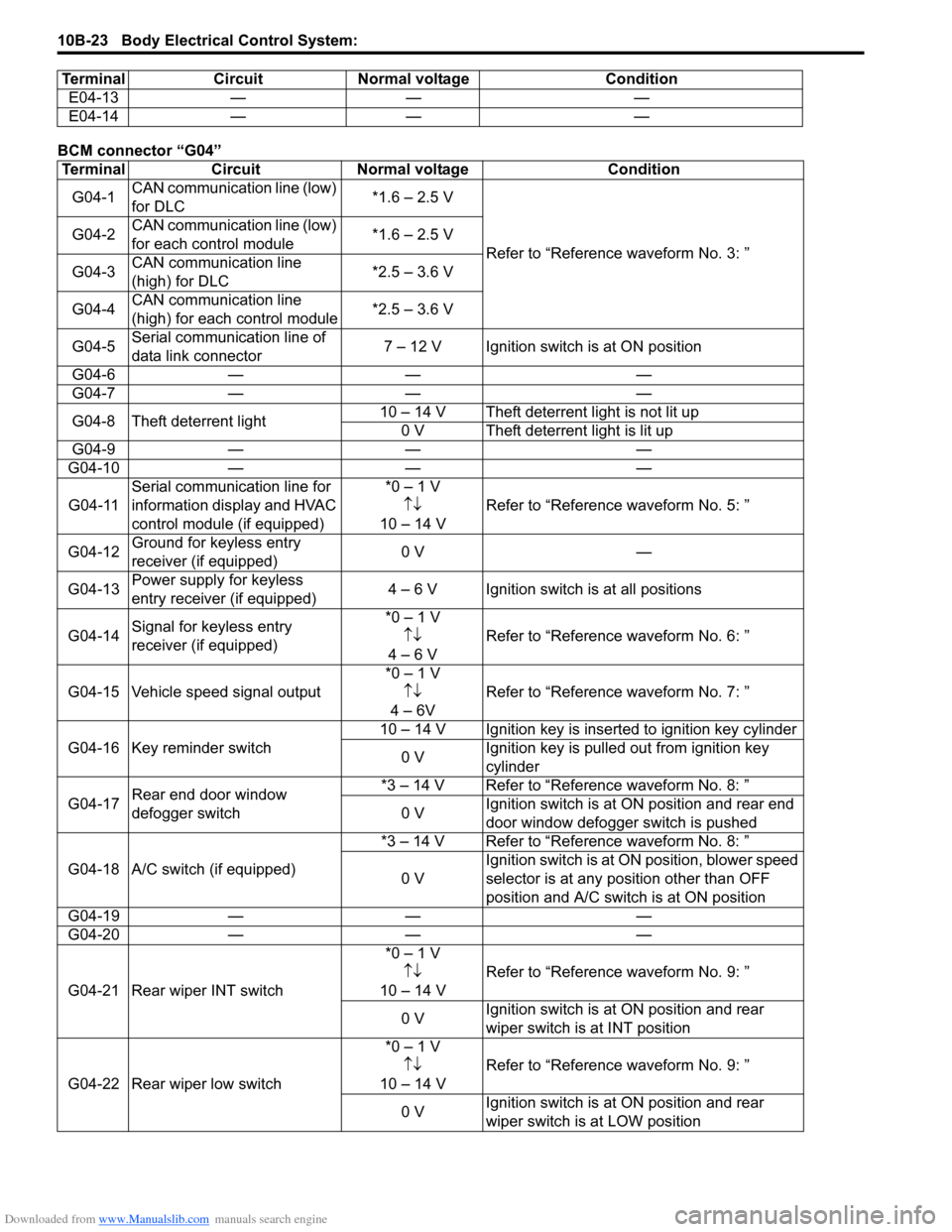
Downloaded from www.Manualslib.com manuals search engine 10B-23 Body Electrical Control System:
BCM connector “G04”E04-13 — — —
E04-14 — — —
Terminal Circuit Normal voltage Condition
G04-1CAN communication line (low)
for DLC*1.6 – 2.5 V
Refer to “Reference waveform No. 3: ” G04-2CAN communication line (low)
for each control module*1.6 – 2.5 V
G04-3CAN communication line
(high) for DLC*2.5 – 3.6 V
G04-4CAN communication line
(high) for each control module*2.5 – 3.6 V
G04-5Serial communication line of
data link connector 7 – 12 V Ignition switch is at ON position
G04-6 — — —
G04-7 — — —
G04-8 Theft deterrent light10 – 14 V Theft deterrent light is not lit up
0 V Theft deterrent light is lit up
G04-9 — — —
G04-10 — — —
G04-11Serial communication line for
information display and HVAC
control module (if equipped)*0 – 1 V
↑↓
10 – 14 VRefer to “Reference waveform No. 5: ”
G04-12Ground for keyless entry
receiver (if equipped)0 V —
G04-13Power supply for keyless
entry receiver (if equipped)4 – 6 V Ignition switch is at all positions
G04-14Signal for keyless entry
receiver (if equipped)*0 – 1 V
↑↓
4 – 6 VRefer to “Reference waveform No. 6: ”
G04-15 Vehicle speed signal output*0 – 1 V
↑↓
4 – 6VRefer to “Reference waveform No. 7: ”
G04-16 Key reminder switch10 – 14 V Ignition key is inserted to ignition key cylinder
0 VIgnition key is pulled out from ignition key
cylinder
G04-17Rear end door window
defogger switch*3 – 14 V Refer to “Reference waveform No. 8: ”
0 VIgnition switch is at ON position and rear end
door window defogger switch is pushed
G04-18 A/C switch (if equipped)*3 – 14 V Refer to “Reference waveform No. 8: ”
0 VIgnition switch is at ON position, blower speed
selector is at any position other than OFF
position and A/C switch is at ON position
G04-19 — — —
G04-20 — — —
G04-21 Rear wiper INT switch*0 – 1 V
↑↓
10 – 14 VRefer to “Reference waveform No. 9: ”
0 VIgnition switch is at ON position and rear
wiper switch is at INT position
G04-22 Rear wiper low switch*0 – 1 V
↑↓
10 – 14 VRefer to “Reference waveform No. 9: ”
0 VIgnition switch is at ON position and rear
wiper switch is at LOW position Terminal Circuit Normal voltage Condition
Page 1497 of 1556
Downloaded from www.Manualslib.com manuals search engine Body Electrical Control System: 10B-24
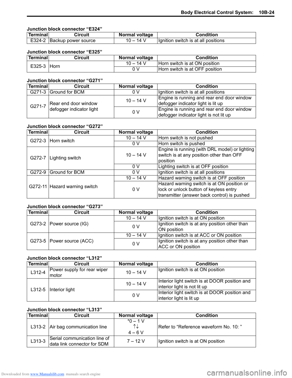
Junction block connector “E324”
Junction block connector “E325”
Junction block connector “G271”
Junction block connector “G272”
Junction block connector “G273”
Junction block connector “L312”
Junction block connector “L313”Terminal Circuit Normal voltage Condition
E324-2 Backup power source 10 – 14 V Ignition switch is at all positions
Terminal Circuit Normal voltage Condition
E325-3 Horn10 – 14 V Horn switch is at ON position
0 V Horn switch is at OFF position
Terminal Circuit Normal voltage Condition
G271-3 Ground for BCM 0 V Ignition switch is at all positions
G271-7Rear end door window
defogger indicator light10 – 14 VEngine is running and rear end door window
defogger indicator light is lit up
0 VEngine is running and rear end door window
defogger indicator light is not lit up
Terminal Circuit Normal voltage Condition
G272-3 Horn switch10 – 14 V Horn switch is not pushed
0 V Horn switch is pushed
G272-7 Lighting switch10 – 14 VEngine is running (with DRL model) or lighting
switch is at any position other than OFF
position
0 V Lighting switch is at OFF position
G272-9 Ground for BCM 0 V Ignition switch is at all positions
G272-11 Hazard warning switch10 – 14 V Hazard warning switch is at OFF position
0 VHazard warning switch is at ON position or
lock or unlock button of keyless entry
transmitter (answer back control) is pushed
Terminal Circuit Normal voltage Condition
G273-2 Power source (IG)10 – 14 V Ignition switch is at ON position
0 VIgnition switch is at any position other than
ON position
G273-5 Power source (ACC)10 – 14 V Ignition switch is at ACC or ON position
0 VIgnition switch is at any position other than
ACC or ON position
Terminal Circuit Normal voltage Condition
L312-4Power supply for rear wiper
motor10 – 14 VIgnition switch is at ON position
L312-5 Interior light10 – 14 VInterior light switch is at DOOR position and
interior light is not lit up
0 VInterior light switch is at DOOR position and
interior light is lit up
Terminal Circuit Normal voltage Condition
L313-2 Air bag communication line*0 – 1 V
↑↓
4 – 6 VRefer to “Reference waveform No. 10: ”
L313-3Serial communication line of
data link connector for SDM7 – 12 V Ignition switch is at ON position