2006 SUZUKI SX4 engine type
[x] Cancel search: engine typePage 483 of 1556

Downloaded from www.Manualslib.com manuals search engine Drive Shaft / Axle: Front 3A-4
9) Remove drive shaft assembly.
10) Remove center bearing support bolts (3) and remove
center bearing support (2) with center shaft (1) from
differential side gear, if equipped.
Installation
CAUTION!
• Be careful not to damage oil seals and
boots when installing drive shaft.
• Do not hit joint boot with hammer.
Inserting joint only by hands is allowed.
• Make sure that differential side joint is
inserted fully and its snap ring is seated as
it was.
Install drive shaft assembly by reversing removal
procedure and noting the following points.
• Tighten each bolt and nut to the specified torque
referring to “Front Drive Shaft Assembly Components
Location”.
• Tighten brake hose mounting bolt to specified torque.
Tightening torque
Brake hose mounting bolt: 25 N·m (2.5 kgf-m,
18.0 lb-ft)
• Fill transaxle with oil as specified referring to “Manual
Transaxle Oil Change in Section 5B” or “A/T Fluid
Change in Section 5A” and “Transfer Oil Change in
Section 3C” (4WD model).
• Check toe setting referring to “Front Wheel Alignment
Inspection and Adjustment in Section 2B” and adjust
as required.
Front Drive Shaft Disassembly and ReassemblyS6RW0D3116004
Disassembly
For DOJ type
CAUTION!
Disassembly of wheel side joint is not
allowed. If any noise or damage exists in it,
replace it as assembly.
1) Remove differential side (or center shaft side) boot
big band (1) as follows.
• For boot big band without joint [A]:
Remove boot big band by tapping boot and band
with plastic hammer. If it is hard to remove boot
big band, cut it using a nipper or an iron saw with
care not to damage joint housing.
• For boot big band with joint [B]:
Draw hooks of boot big band together and remove
band.3
2
1I2RH01310007-01
I4RH0A310004-01
Page 485 of 1556

Downloaded from www.Manualslib.com manuals search engine Drive Shaft / Axle: Front 3A-6
For tripod joint type
CAUTION!
• Disassembly of wheel side joint is not
allowed. If any noise or damage exists in it,
replace it as assembly.
• Do not disassemble tripod joint spider. If
any malcondition is found in it, replace it
as differential side joint assembly.
1) Remove differential side (or center shaft side) boot
big band (1) as follows.
• For boot big band without joint:
Remove boot big band by tapping boot and band
with plastic hammer. If it is hard to remove boot
big band, cut it using a nipper or an iron saw with
care not to damage joint housing.
• For boot big band with joint:
Draw hooks of boot big band together and remove
band.2) Wipe off grease from shaft and take off snap ring (1)
using snap ring pliers (2).
3) Remove tripod joint spider (1) using 3 arms puller
(2).
CAUTION!
To prevent any problem caused by washing
solution, do not wash tripod joint except its
housing. Degreasing of tripod joint with cloth
is allowed.
4) Remove differential side (or center shaft side) boot
small band, and then pull out differential side (or
center shaft side) boot from shaft.
5) Remove damper from shaft, if equipped.
6) Undo caulking (5) of wheel side boot big band (1)
and small band (3) using flat end rod (2) or the like,
then pull out wheel side boot (4) from shaft.
[A]: For boot big band without joint
[B]: For boot big band with joint
I4RH0A310004-01
I7RW01311003-01
I3RH0A311004-01
I4RS0A310006-01
Page 486 of 1556

Downloaded from www.Manualslib.com manuals search engine 3A-7 Drive Shaft / Axle: Front
Reassembly
For DOJ type
Judging from abnormality noted before disassembly and
what is found through visual check of component parts
after disassembly, prepare replacing parts and proceed
to reassembly.
Make sure that wheel side joint assembly and DOJ
housing are washed thoroughly and air dried.
Replace boot(s) with new one(s).
CAUTION!
• Do not wash boots in degreaser such as
gasoline or kerosene. etc. Washing in
degreaser causes deterioration of boot.
• To ensure full performance of joint as
designed, be sure to distinguish between
two types of grease in repair set and apply
specified volume to respective joint
referring to the followings for identification
of the grease.
1) Wash disassembled parts (except boots). After
washing, dry parts completely by blowing air.
2) Clean boots with cloth.
3) Apply grease to wheel side joint. Use specified
grease in tube in wheel side boot set as a spare
parts.
Grease color
: Black
Amount
: 55 – 75 g (1.9 – 2.6 oz)
4) Install wheel side boot on shaft.
5) Fill up boot inside with specified grease.
6) Fit boot (1) to grooves of shaft and housing (2).
7) Insert screw driver into boot and allow air to enter
boot so that air pressure in boot becomes the same
as atmospheric pressure.
8) Place new wheel side boot big band (3) and small
band (4) onto boot putting band outer end (1) against
forward rotation (2) as shown in figure.9) Fasten boot bands (1) using special tool as shown in
figure.
CAUTION!
Do not squeeze or distort boot when
fastening it with bands.
Distorted boot caused by squeezing air may
reduce its durability.
Distance “a”
: 2.6 ± 1.4 mm (0.102 ± 0.055 in.)
Special tool
(A): 09943–57010
21I5RS0B310007-01
I4RS0A310009-01
(A)
1
(A)
1
“a”
1
I5RS0B310008-01
Page 489 of 1556

Downloaded from www.Manualslib.com manuals search engine Drive Shaft / Axle: Front 3A-10
For tripod joint type
Judging from abnormality noted before disassembly and
what is found through visual check of component parts
after disassembly, prepare replacing parts and proceed
to reassembly.
Make sure that wheel side joint assembly (1) and tripod
joint housing (2) are washed thoroughly and air dried.
Replace boot(s) (3) with new one(s).
CAUTION!
• Do not wash boots in degreaser such as
gasoline or kerosene. etc. Washing in
degreaser causes deterioration of boot.
• To ensure full performance of joint as
designed, be sure to distinguish between
two types of grease in repair set and apply
specified volume to respective joint
referring to the followings for identification
of the grease.
1) Wash disassembled parts (except boots). After
washing, dry parts completely by blowing air.
2) Clean boots with cloth.
3) Apply grease to wheel side joint. Use specified
grease in tube in wheel side boot set as a spare
parts.
Grease color
: Black
Amount
: 55 – 75 g (1.9 – 2.6 oz)
4) Install wheel side boot on shaft.
5) Fill up boot inside with specified grease.
6) Place new wheel side boot big band (3) and small
band (4) onto boot putting band outer end (1) against
forward rotation (2) as shown in figure.7) Fasten boot bands (1) securely using special tool as
shown in figure.
CAUTION!
Do not squeeze or distort boot when
fastening it with bands.
Distorted boot caused by squeezing air may
reduce its durability.
Distance “a”
: 2.6 ± 1.4 mm (0.102 ± 0.055 in.)
Special tool
(A): 09943–57010
[A]: Wheel side
[B]: Differential side (or center shaft side)
I4RS0A310007-01
I4RS0A310009-01
(A)
1
(A)
1
“a”
1
I5RS0B310008-01
Page 504 of 1556

Downloaded from www.Manualslib.com manuals search engine 3B-7 Differential:
CAN Communication System DescriptionS6RW0D3201010
Refer to “CAN Communication System Description in Section 1A” for CAN communication system description.
When 4WD control module receive the signal of abnormal as following information, vehicle is not changed to 4WD-
auto and 4WD-lock position.
4WD Control Module Transmission Data
4WD Control Module Reception Data
ECMCombination
Meter
TransmitDATA 4WD
4WD mode status
4WD auto mode
indication status
4WD lock mode
indication status
4WD diagnostic
trouble codes control
module
4WD clutch
engagement percent
ESP® hydraulic unit /
control module
(if equipped)
4WD clutch control
request impossibility
I7RW01320013-01
Accelerator position
Engine speedECM
DATA
Brake pedal switch signal
4WD
control
moduleWheel speed signal
(front right)
Wheel speed signal
(front left)
Wheel speed signal
(rear right)
Wheel speed signal
(rear left)
ABS hydraulic
unit /control
module
(if equipped)
ESP® hydraulic
unit /control
module
(if equipped)
ABS active
ESP® status signal
Clutch control request for
4WD active
Clutch control request
percent
Engine type signal
Engine torque signal
Receive
I7RW01320002-03
Page 647 of 1556

Downloaded from www.Manualslib.com manuals search engine Table of Contents 5-iii
Diagnostic Information and Procedures ............ 5B-5
Manual Transaxle Symptom Diagnosis............... 5B-5
Repair Instructions .............................................. 5B-5
Manual Transaxle Oil Level Check ..................... 5B-5
Manual Transaxle Oil Change ............................ 5B-6
Differential Side Oil Seal Replacement ............... 5B-7
Gear Shift Control Lever and Cable
Components...................................................... 5B-8
Gear Shift Control Lever and Cable Removal
and Installation .................................................. 5B-9
Gear Select Control Cable Adjustment ............... 5B-9
Back Up Light Switch Removal and
Installation ....................................................... 5B-10
Back Up Light Switch Inspection ....................... 5B-10
Manual Transaxle Unit Components ................. 5B-11
Manual Transaxle Unit Dismounting and
Remounting..................................................... 5B-12
Gear Shift and Select Shaft Assembly
Components.................................................... 5B-13
Gear Shift and Select Shaft Assembly
Removal and Installation................................. 5B-14
Gear Shift and Select Shaft Assembly
Disassembly and Reassembly ........................ 5B-15
Manual Transaxle Assembly Components........ 5B-16
Fifth Gear Disassembly and Reassembly ......... 5B-17
Manual Transaxle Assembly Disassembly
and Reassembly ............................................. 5B-19
Right Case Disassembly and Reassembly ....... 5B-24
Left Case Disassembly and Reassembly.......... 5B-25
Input Shaft and Countershaft Components....... 5B-27
Input Shaft Disassembly and Reassembly........ 5B-28
Countershaft Disassembly and Reassembly .... 5B-31
Gear Shift Shaft Components ........................... 5B-35
5th and Reverse Gear Shift Shafts
Disassembly and Reassembly ........................ 5B-35
Gear Shift Shaft and Fork Inspection ................ 5B-35
Differential Components ................................... 5B-36Differential Disassembly and Reassembly ........ 5B-36
Specifications .....................................................5B-38
Tightening Torque Specifications ...................... 5B-38
Special Tools and Equipment ...........................5B-39
Recommended Service Material ....................... 5B-39
Special Tool ...................................................... 5B-39
Clutch ....................................................... 5C-1
General Description .............................................5C-1
Clutch (Hydraulic Type) Construction .................5C-1
Diagnostic Information and Procedures ............5C-2
Clutch System Symptom Diagnosis ....................5C-2
Repair Instructions ..............................................5C-3
Clutch Pedal Inspection ......................................5C-3
Clutch Fluid Level Inspection ..............................5C-3
Air Bleeding of Clutch System.............................5C-3
Clutch Fluid Pipe and Hose Location ..................5C-4
Clutch Fluid Pipe Removal and Installation.........5C-4
Clutch Fluid Pipe Inspection................................5C-4
Clutch Master Cylinder Removal and
Installation .........................................................5C-5
Clutch Operating Cylinder Assembly
Removal and Installation ...................................5C-5
Clutch Operating Cylinder Assembly
Inspection ..........................................................5C-6
Clutch Cover, Clutch Disc and Flywheel
Components ......................................................5C-6
Clutch Cover, Clutch Disc and Flywheel
Removal and Installation ...................................5C-7
Clutch Cover, Clutch Disc and Flywheel
Inspection ..........................................................5C-8
Specifications .......................................................5C-9
Tightening Torque Specifications ........................5C-9
Special Tools and Equipment ...........................5C-10
Recommended Service Material .......................5C-10
Special Tool ......................................................5C-10
Page 651 of 1556

Downloaded from www.Manualslib.com manuals search engine Automatic Transmission/Transaxle: 5A-3
General Description
A/T DescriptionS6RW0D5101001
This automatic transaxle is electronic control full automatic transaxle with forward 3-speed plus overdrive (O/D) and
reverse 1-speed.
The torque converter is a 3-element, 1-step and 2-phase type and is equipped with an automatically controlled lock-up
mechanism.
The gear change device consists of a ravigneau type planetary gear unit, 3 multiple disc type clutches, 3 multiple disc
type brakes and 2 one-way clutches.
The hydraulic pressure control device consists of a valve body assembly, pressure control solenoid valve (linear
solenoid), 2 shift solenoid valves, TCC solenoid valve (TCC pressure control solenoid valve) (linear solenoid) and a
timing solenoid valve. Optimum line pressure complying with engine torque is produced by the pressure control
solenoid valve in dependence upon control signal from transmission control module (TCM). This makes it possible to
control the line pressure with high accuracy in accordance with the engine power and running conditions to achieve
smooth shifting characteristics and high efficiency.
A clutch-to-clutch control system is provided for shifting between 3rd gear and 4th gear. This clutch-to-clutch control
system is made to function optimally, so that hydraulic pressure controls such as shown below are conducted.
• When upshifting from 3rd gear to 4th gear, to adjust the drain hydraulic pressure at releasing the forward clutch, a
timing solenoid valve is used to switch a hydraulic passage with an orifice to another during shifting.
• When downshifting from 4th gear to 3rd gear, to adjust the line pressure applied to the forward clutch at engaging
the forward clutch, a timing solenoid valve is used to switch a hydraulic passage with an orifice to another during
shifting.
• When upshifting from 3rd gear to 4th gear with engine throttle opened, to optimize the line pressure applied to the
forward clutch at releasing the forward clutch, the learning control is processed to compensate the switching timing
of the timing solenoid at every shifting.
• When downshifting from 4th gear to 3rd gear with engine throttle opened, to optimize the line pressure applied to
the forward clutch at engaging the forward clutch, the learning control is processed to compensate the line pressure
at every shifting.
Employing the ravigneau type planetary gear unit and this clutch-to-clutch control system greatly simplifies the
construction to make possible a lightweight and compact transaxle.
A line pressure learning control is conducted to provide optimum shifting time at every upshifting with engine throttle
opened. If long upshifting time is detected, the subsequent line pressure applied during upshifting is intensified. On the
contrary, if short upshifting time is detected, the subsequent line pressure applied during upshifting is weakened.
Page 653 of 1556
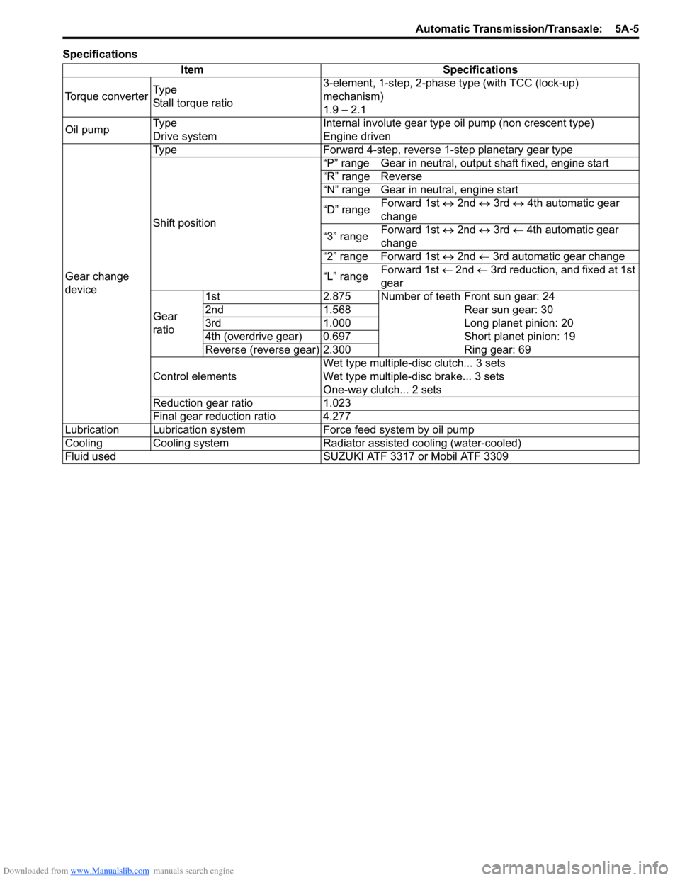
Downloaded from www.Manualslib.com manuals search engine Automatic Transmission/Transaxle: 5A-5
Specifications
Item Specifications
Torque converterTy p e
Stall torque ratio3-element, 1-step, 2-phase type (with TCC (lock-up)
mechanism)
1.9 – 2.1
Oil pumpTy p e
Drive systemInternal involute gear type oil pump (non crescent type)
Engine driven
Gear change
deviceType Forward 4-step, reverse 1-step planetary gear type
Shift position“P” range Gear in neutral, output shaft fixed, engine start
“R” range Reverse
“N” range Gear in neutral, engine start
“D” range Forward 1st ↔ 2nd ↔ 3rd ↔ 4th automatic gear
change
“3” rangeForward 1st ↔ 2nd ↔ 3rd ← 4th automatic gear
change
“2” range Forward 1st ↔ 2nd ← 3rd automatic gear change
“L” rangeForward 1st ← 2nd ← 3rd reduction, and fixed at 1st
gear
Gear
ratio1st 2.875 Number of teeth Front sun gear: 24
2nd 1.568 Rear sun gear: 30
3rd 1.000 Long planet pinion: 20
4th (overdrive gear) 0.697 Short planet pinion: 19
Reverse (reverse gear) 2.300 Ring gear: 69
Control elementsWet type multiple-disc clutch... 3 sets
Wet type multiple-disc brake... 3 sets
One-way clutch... 2 sets
Reduction gear ratio 1.023
Final gear reduction ratio 4.277
Lubrication Lubrication system Force feed system by oil pump
Cooling Cooling system Radiator assisted cooling (water-cooled)
Fluid used SUZUKI ATF 3317 or Mobil ATF 3309