2006 SUZUKI SX4 8b-18
[x] Cancel search: 8b-18Page 1029 of 1556

Downloaded from www.Manualslib.com manuals search engine Table of Contents 8- i
8
Section 8
CONTENTS
Restraint
Precautions ................................................. 8-1
Precautions............................................................. 8-1
Precautions on Restraint ....................................... 8-1
Seat Belts ................................................. 8A-1
Precautions........................................................... 8A-1
Precautions on Service and Diagnosis of Seat
Belt .................................................................... 8A-1
General Description ............................................. 8A-2
Seat Belt Construction ........................................ 8A-2
Diagnostic Information and Procedures ............ 8A-3
Repair and Inspection Required after
Accident ............................................................ 8A-3
Repair Instructions .............................................. 8A-4
Front Seat Belt Components ............................... 8A-4
Front Seat Belt Removal and Installation ............ 8A-5
Front Seat Belt Inspection................................... 8A-6
Rear Seat Belt Components ............................... 8A-7
Rear Seat Belt Removal and Installation ............ 8A-8
Rear Seat Belt Inspection ................................... 8A-8
Specifications....................................................... 8A-8
Tightening Torque Specifications ........................ 8A-8
Air Bag System ........................................ 8B-1
Precautions........................................................... 8B-1
Precautions on Service and Diagnosis of Air
Bag System....................................................... 8B-1
Precautions on Handling and Storage of Air
Bag System Components ................................. 8B-1
Precautions on Disposal of Air Bag and Seat
Belt Pretensioner .............................................. 8B-5
General Description ............................................. 8B-5
Air Bag System Construction .............................. 8B-5
Air Bag System Block Diagram ........................... 8B-6
Air Bag System Input / Output Table .................. 8B-7
Schematic and Routing Diagram ........................ 8B-8
Air Bag System Wiring Circuit Diagram .............. 8B-8
Component Location ......................................... 8B-11
Air Bag System Components, Wiring and
Connectors Location ....................................... 8B-11
Diagnostic Information and Procedures .......... 8B-12
Air Bag Diagnostic System Check .................... 8B-12
Air Bag Diagnostic System Check Flow ............ 8B-13
DTC Table ......................................................... 8B-14DTC Check........................................................ 8B-18
DTC Clearance ................................................. 8B-18
Scan Tool Data ................................................. 8B-18
“AIR BAG” Warning Light Comes ON Steady ... 8B-19
“AIR BAG” Warning Light Does Not Come ON .. 8B-22
Serial Data Link Circuit Check .......................... 8B-23
DTC B1013: SDM Internal Failure .................... 8B-25
DTC B1014: “AIR BAG” Warning Light Circuit .. 8B-26
DTC B1016: Power Supply Voltage too High.... 8B-26
DTC B1017: Power Supply Voltage too Low .... 8B-27
DTC B1021: Front Air Bag Deployment
Record............................................................. 8B-28
DTC B1024 / B1025: Side Air-Bag
Deployment Record ........................................ 8B-29
DTC B1026: Seat Belt Pretensioner
Activation Record ............................................ 8B-29
DTC B1027: Number of Deployment Times
Exceeded Limit................................................ 8B-30
DTC B1031: Driver Air Bag Circuit High
Resistance ...................................................... 8B-31
DTC B1032: Driver Air Bag Circuit Low
Resistance ...................................................... 8B-33
DTC B1033: Driver Air Bag Circuit Shorted to
Ground ............................................................ 8B-35
DTC B1034: Driver Air Bag Circuit Shorted to
Power Supply .................................................. 8B-37
DTC B1041: Passenger Air Bag Circuit High
Resistance ...................................................... 8B-40
DTC B1042: Passenger Air Bag Circuit Low
Resistance ...................................................... 8B-43
DTC B1043: Passenger Air Bag Circuit
Shorted to Ground........................................... 8B-45
DTC B1044: Passenger Air Bag Circuit
Shorted to Power Supply ................................ 8B-46
DTC B1051 / B1055: Seat Belt Pretensioner
Circuit High Resistance ................................... 8B-48
DTC B1052 / B1056: Seat Belt Pretensioner
Circuit Low Resistance.................................... 8B-51
DTC B1053 / B1057: Seat Belt Pretensioner
Shorted to Ground........................................... 8B-52
DTC B1054 / B1058: Seat Belt Pretensioner
Circuit Shorted to Power Supply ..................... 8B-54
DTC B1061 / B1065: Side-Air Bag Circuit
High Resistance .............................................. 8B-55
Page 1057 of 1556

Downloaded from www.Manualslib.com manuals search engine Air Bag System: 8B-18
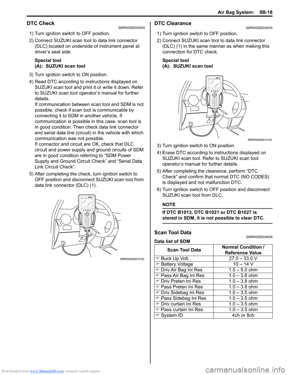
DTC CheckS6RW0D8204004
1) Turn ignition switch to OFF position.
2) Connect SUZUKI scan tool to data link connector
(DLC) located on underside of instrument panel at
driver’s seat side.
Special tool
(A): SUZUKI scan tool
3) Turn ignition switch to ON position.
4) Read DTC according to instructions displayed on
SUZUKI scan tool and print it or write it down. Refer
to SUZUKI scan tool operator’s manual for further
details.
If communication between scan tool and SDM is not
possible, check if scan tool is communicable by
connecting it to SDM in another vehicle. If
communication is possible in this case, scan tool is
in good condition. Then check data link connector
and serial data line (circuit) in the vehicle with which
communication was not possible.
If connector and circuit are OK, check that DLC
circuit and power supply and ground circuits of SDM
are in good condition referring to “SDM Power
Supply and Ground Circuit Check” and “Serial Data
Link Circuit Check”.
5) After completing the check, turn ignition switch to
OFF position and disconnect SUZUKI scan tool from
data link connector (DLC) (1).
DTC ClearanceS6RW0D8204005
1) Turn ignition switch to OFF position.
2) Connect SUZUKI scan tool to data link connector
(DLC) (1) in the same manner as when making this
connection for DTC check.
Special tool
(A): SUZUKI scan tool
3) Turn ignition switch to ON position.
4) Erase DTC according to instructions displayed on
SUZUKI scan tool. Refer to SUZUKI scan tool
operator’s manual for further details.
5) After completing the clearance, perform “DTC
Check” and confirm that normal DTC (NO CODES)
is displayed and not malfunction DTC.
6) Turn ignition switch to OFF position and disconnect
SUZUKI scan tool from DLC.
NOTE
If DTC B1013, DTC B1021 or DTC B1027 is
stored in SDM, it is not possible to clear DTC.
Scan Tool DataS6RW0D8204006
Data list of SDM
I5RW0A820010-03
Scan Tool DataNormal Condition /
Reference Value
�) Buck Up Volt 27.0 – 33.0 V
�) Battery Voltage 10 – 14 V
�) Driv Air Bag Ini Res 1.5 – 5.0 ohm
�) Pass Air Bag Ini Res 1.0 – 3.8 ohm
�) Driv Preten Ini Res 1.0 – 3.8 ohm
�) Pass Preten Ini Res 1.0 – 3.8 ohm
�) Driv Sidebag Ini Res 1.0 – 3.5 ohm
�) Pass Sidebag Ini Res 1.0 – 3.5 ohm
�) Driv curtain Ini Res 1.0 – 3.5 ohm
�) Pass curtain Ini Res 1.0 – 3.5 ohm
�) System ID 4ch or 8ch
I5RW0A820010-03