2006 SUZUKI SX4 engine type
[x] Cancel search: engine typePage 405 of 1556
Downloaded from www.Manualslib.com manuals search engine Ignition System: 1H-10
Specifications
Tightening Torque SpecificationsS6RW0D1807001
Reference:
For the tightening torque of fastener not specified in this section, refer to “Fasteners Information in Section 0A”.
Special Tools and Equipment
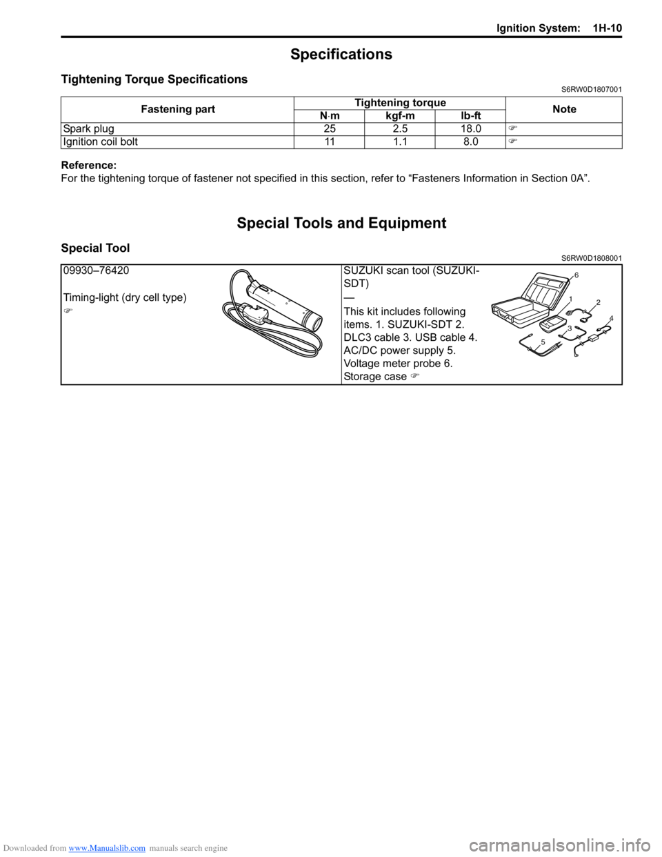
Special ToolS6RW0D1808001
Fastening partTightening torque
Note
N⋅mkgf-mlb-ft
Spark plug 25 2.5 18.0)
Ignition coil bolt 11 1.1 8.0)
09930–76420 SUZUKI scan tool (SUZUKI-
SDT)
Timing-light (dry cell type) —
)This kit includes following
items. 1. SUZUKI-SDT 2.
DLC3 cable 3. USB cable 4.
AC/DC power supply 5.
Voltage meter probe 6.
Storage case )
1
2
34
56
Page 415 of 1556

Downloaded from www.Manualslib.com manuals search engine Charging System: 1J-1
Engine
Charging System
General Description
Battery DescriptionS6RW0D1A01001
The battery has three major functions in the electrical
system.
• It is a source of electrical energy for cranking the
engine.
• It acts as a voltage stabilizer for the electrical system.
• It can, for a limited time, provide energy when the
electrical load exceeds the output of the generator.
Carrier and Hold-Down
The battery carrier should be in good condition so that it
will support the battery securely and keep it level. Before
installing the battery, the battery carrier and hold-down
clamp should be clean and free from corrosion and
make certain there are no parts in carrier.
To prevent the battery from shaking in its carrier, the
hold-down bolts should be tight enough but not over-
tightened.
Electrolyte Freezing
The freezing point of electrolyte depends on its specific
gravity. Since freezing may ruin a battery, it should be
protected against freezing by keeping it in a fully
charged condition. If a battery is frozen accidentally, it
should not be charged until it is warmed.
Sulfation
If the battery is allowed to stand for a long period in
discharged condition, the lead sulfate becomes
converted into a hard, crystalline substance, which will
not easily turn back to the active material again during
the subsequent recharging. “Sulfation” means the result
as well as the process of that reaction. Such a battery
can be revived by very slow charging and may be
restored to usable condition but its capacity is lower than
before.Built-In Indicator (If Equipped)
The battery has a built-in temperature compensated
indicator in the top of the battery. This indicator is to be
used with the following diagnostic procedure. When
checking the indicator, make sure that the battery has a
clean top. A light may be needed in some poorly-lit
areas.
Three types of indication available under normal
operation are as follows.
•Green dot
Battery is sufficiently charged for testing.
•Dark
Battery must be charged before testing. If there is a
cranking complaint, battery should be tested as
described in “Battery Inspection”. Charging and
electrical systems should also be checked at this time.
•Clear or light yellow
This means that fluid level is below the bottom of
hydrometer. Its possible cause is excessive or
prolonged charging, a broken case, excessive tipping
or normal battery deterioration. When the battery is
found in such condition, it is possible that high
charging voltage is caused by the faulty charging
system and therefore, charging and electrical systems
need to be checked. If there is a trouble in cranking
and its cause lies in the battery, it should be replaced.
I2RH011A0001-01
Page 427 of 1556

Downloaded from www.Manualslib.com manuals search engine Charging System: 1J-13
Specifications
Charging System SpecificationsS6RW0D1A07003
Battery
NOTE
The battery used in each vehicle is one of the following two types, depending on specification.
Battery
: 46B24R (40.6AH/5HR), 55B24R (42.5AH/5HR) 12V
Generator
Tightening Torque SpecificationsS6RW0D1A07004
NOTE
The specified tightening torque is also described in the following.
“Generator Dismounting and Remounting”
“Generator Components”
Reference:
For the tightening torque of fastener not specified in this section, refer to “Fasteners Information in Section 0A”. Battery type 46B24R 55B24R
Rated capacity AH/5HR, 12 Volts 40.6 42.5
Electrolyte L (US / lmp pt.) — 2.8 (5.92 / 4.93)
Type 70 A type
Rated voltage 12 V
Nominal output 70 A
Permissible max. speed 18,000 r/min.
No-load speed 1020 r/min. (rpm)
Regulated voltage 14.2 – 14.8 V (Hi), 12.5 – 13.1 V (Lo)
Exposed brush length Standard: 10.5 mm (0.41 in.)
Limit: 1.5 mm (0.05 in.)
Permissible ambient temperature –30 to 90 °C (–22 to 194 °F)
Polarity Negative ground
Rotation Clockwise viewed from pulley side
Fastening partTightening torque
Note
N⋅mkgf-mlb-ft
Generator bracket bolt 25 2.5 18.0)
Generator pivot bolt 50 5.0 36.0)
Generator adjusting bolt
Tighten 7.0 0.7 5.0by the specified
procedure. )
Page 470 of 1556

Downloaded from www.Manualslib.com manuals search engine 2D-1 Wheels and Tires:
Suspension
Wheels and Tires
General Description
Tires DescriptionS6RW0D2401001
The tire is of tubeless type. The tire is designed to
operate satisfactorily with loads up to the full rated load
capacity when inflated to the recommended inflation
pressures.
Correct tire pressures and driving habits have an
important influence on tire life. Heavy cornering,
excessively rapid acceleration, and unnecessary sharp
braking increase tire wear.
Tire Placard
The “Tire Placard” is located on the left or right door lock
pillar and should be referred to tire information.
The placard lists the maximum load, tire size and cold
tire pressure where applicable.
NOTE
Whether rim size and/or maximum load are
listed or not depends on regulations of each
country.
Inflation of Tires
The pressure recommended for any model is carefully
calculated to give a satisfactory ride, stability, steering,
tread wear, tire life and resistance to bruises.
Tire pressure, with tires cold, (after vehicle has set for 3
hours or more, or driven less than one mile) should be
checked monthly or before any extended trip. Set to the
specifications on the “Tire Placard” located on the left or
right door lock pillar.
It is normal for tire pressure to increase when the tires
become hot during driving.
Do not bleed or reduce tire pressure after driving.
Bleeding reduces the “Cold Inflation Pressure”.
Higher than recommended pressure can cause:
• Hard ride
• Tire bruising or carcass damage
• Rapid tread wear at center of tire
Unequal pressure on same axle can cause:
• Uneven braking
• Steering lead
• Reduced handling
• Swerve on accelerationLower than recommended pressure can cause:
• Tire squeal on turns
• Hard Steering
• Rapid and uneven wear on the edges of the tread
• Tire rim bruises and rupture
• Tire cord breakage
• High tire temperature
• Reduced handling
• High fuel consumption
Matched Tires and Wheels (Steel Type)
Tires and wheels are match mounted at the assembly
plant.
This means that the radially stiffest part of the tire, or
“high spot”, is matched to the smallest radius or “low
spot” of the wheel.
This is done to provide the smoothest possible ride.
The “high spot” of the tire is originally marked by paint
dot (1) on the outboard sidewall. This paint dot will
eventually wash off the tire.
The “low spot” of the wheel is originally marked by paint
dot (2) on the wheel rim-flange. Properly assembled, the
wheel rims’ paint dot should be aligned with the tires’
paint dot as shown in figure.
Whenever a tire is dismounted from its wheel, it should
be remounted so that the tire and wheel are matched. If
the tire’s paint dot cannot be located, a line should be
scribed on the tire and wheel before dismounting to
assure that it is remounted in the same position.
I2RH01240001-01
Page 471 of 1556

Downloaded from www.Manualslib.com manuals search engine Wheels and Tires: 2D-2
Replacement Tires
When replacement is necessary, the original equipment
type tire should be used. Refer to the Tire Placard.
Replacement tires should be of the same size, load
range and construction as those originally on the vehicle.
Use of any other size or type tire may affect ride,
handling, speedometer / odometer calibration, vehicle
ground clearance and tire or snow chain clearance to the
body and chassis.
It is recommended that new tires be installed in pairs on
the same axle. If necessary to replace only one tire, it
should be paired with the tire having the most tread, to
equalize braking traction.
WARNING!
Do not mix different types of tires on the
same vehicle such as radial, bias and bias-
belted tires except in emergencies, because
handling may be seriously affected and may
result in loss of control.
The metric term for tire inflation pressure is the kilo
pascal (kPa). Tire pressures is usually printed in both
kPa and kgf/cm
2 on the “Tire Placard”.
Metric tire gauges are available from tool suppliers.
The chart, shown in the table, converts commonly used
inflation pressures from kPa to kgf/cm
2 and psi.
Wheels DescriptionS6RW0D2401002
Wheel Maintenance
Wheel repairs that use welding, heating, or peening are
not approved. All damaged wheels should be replaced.
Replacement Wheels
Wheels must be replaced if they are bent, dented, have
excessive lateral or radial runout, air leak through welds,
have elongated bolt holes, if lug wheel bolts won’t stay
tight, or if they are heavily rusted. Wheels with greater
runout than shown in the following may cause
objectional vibrations.
Replacement wheels must be equivalent to the original
equipment wheels in load capacity, diameter, rim with
offset and mounting configuration. A wheel of improper
size or type may affect wheel and bearing life, brake
cooling, speedometer / odometer calibration, vehicle
ground clearance and tire clearance to body and
chassis.How to Measure Wheel Runout
To measure the wheel runout, it is necessary to use an
accurate dial indicator. The tire may be on or off the
wheel. The wheel should be installed to the wheel
balancer of the like for proper measurement.
Take measurements of both lateral runout “a” and radial
runout “b” at both inside and outside of the rim flange.
With the dial indicator set in place securely, turn the
wheel one full revolution slowly and record every reading
of the indicator.
When the measured runout exceeds the specification
and correction by the balancer adjustment is impossible,
replace the wheel. If the reading is affected by welding,
paint or scratch, it should be ignored.
Lateral runout limit “a”
Aluminum wheel: 0.3 mm (0.012 in.)
Steel wheel: 0.9 mm (0.035 in.)
Radial runout limit “b”
Aluminum wheel: 0.3 mm (0.012 in.)
Steel wheel: 0.7 mm (0.028 in.)
Metric Lug Nuts and Wheel Studs
All models use metric lug nuts and wheel studs.
Metric lug nuts and wheel studs size
M12 x 1.25
If a broken stud is found, see “Front Wheel Hub, Disc,
Bolt and Bearing Check in Section 2B”, “Front Wheel
Hub, Steering Knuckle and Wheel Bearing Removal and
Installation in Section 2B”, “Rear Wheel Hub Assembly
Removal and Installation in Section 2C”. kPa kgf/cm
2psi
Conversion: 1 psi =
6.895 kPa 1 kgf/cm
2 =
98.066 kPa160 1.6 23
180 1.8 26
200 2.0 29
220 2.2 32
240 2.4 35
260 2.6 38
280 2.8 41
300 3.0 44
320 3.2 47
340 3.4 50I4RS0A240001-01
I2RH01240003-01
Page 473 of 1556

Downloaded from www.Manualslib.com manuals search engine Wheels and Tires: 2D-4
Equipment manufacture’s recommendations
Radial Tire Lead / Pull DescriptionS6RW0D2401006
“Lead / Pull” is the deviation of the vehicle from a straight
path on a level road even with no pressure on the
steering wheel.
Lead is usually caused by the following conditions.
• Improper tire and wheel alignment.
• Uneven brake assemblies.
• Tire construction.
The way in which a tire is built can produce lead in a
vehicle. An example of this is placement of the belt. Off
center belts on radial tires can cause the tire to develop
a side force while rolling straight down the road. If one
side of the tire has a little larger diameter than the other,
the tire will tend to roll to one side. This will develop a
side force which can produce vehicle lead.
The procedure in the figure (Lead Diagnosis) should be
used to make sure that wheel alignment is not mistaken
for tire lead.
• Part of the lead diagnosis procedure is different from
the proper tire rotation pattern currently in the owner
and service manuals. If a medium to high mileage tire
is moved to the other side of the vehicle, be sure to
check that ride roughness has not developed
• Rear tires will not cause lead.
Balancing Wheels DescriptionS6RW0D2401007
There are two types of wheel and tire balance: static and
dynamic. Static balance, as shown in figure, is the equal
distribution of weight around the wheel. Wheels that are
statically unbalanced cause a bouncing action called
tramp. This condition will eventually cause uneven tire
wear.Dynamic balance, as shown in figure, is the equal
distribution of weight on each side of the wheel
centerline so that when the tire spins there is no
tendency for the assembly to move from side to side.
Wheels that are dynamically unbalanced may cause
shimmy.
Inflate tires to recommended pressure
Road test vehicle on level unrouned road in both directions
Switch front tires side to side and road test again
Lead corrected,
if roughness results, replace tiresLeads in same directionLeads reverses direction
Put tires back in original position
and check alignmentInstall a known-good tire on one front side
Lead remains install a known-good
tire in place of other front tire
Lead remains known-good tires are not goodLead corrected replace tire
Lead corrected replace tire
I2RH01240007-01
1. Heavy spot wheel tramp [A]: Before correction
2. Balance weights addition point [B]: Corrective weights
3. C/L of spindle
1. Heavy spot wheel shimmy [C]: Before correction
2. Balance weights addition point [D]: Corrective weights
3. C/L of spindle
I2RH01240008-01
I2RH01240009-01
Page 475 of 1556

Downloaded from www.Manualslib.com manuals search engine Wheels and Tires: 2D-6
Wheel (with Tire) Removal and InstallationS6RW0D2406003
Removal
CAUTION!
Never use heat to loosen tight wheel because
the application of heat to wheel causes the
wheel life shorter and the wheel bearing
damage.
1) Loosen wheel nuts by approximately 180° (half a
rotation).
2) Hoist vehicle.
3) Make sure that the vehicle will not fall off by trying to
move vehicle body in both ways.
4) Remove wheel nuts except one.
5) Support the wheel and/or tire not to drop the wheel
and then remove the nut left with the wheel.
Installation
For installation, reverse removal procedure, noting the
following.
• Wheel nuts must be tightened in sequence and to
specified torque to avoid bending wheel or brake disc
or drum as shown in the figure.
NOTE
Before installing wheels, remove any build-
up of corrosion on wheel mounting surface
and brake disc or drum mounting surface by
scraping and wire brushing. Installing wheels
without good metal-to-metal contact at
mounting surfaces can cause wheel bolts to
loosen, which can later allow a wheel to
come off while vehicle is moving.
Tightening order
“1” – “2” – “3” – “4” – “5”
Tightening torque
Wheel nut (a): 85 N·m (8.5 kgf-m, 61.5 lb-ft)
Tire Mounting and DismountingS6RW0D2406004
WARNING!
Do not stand over tire when inflating. Bead
may break when bead snaps over rim’s safety
hump and cause serious personal injury.
Do not exceed specified pressure when
inflating. If specified pressure will not seat
beads, deflate, re-lubricate and reinflate.
Over inflation may cause bead to break and
cause serious personal injury.
Use a tire changing machine to mount or dismount tires.
Follow equipment manufacturer’s instructions. Do not
use hand tools or tire irons alone to change tires as they
may damage tire beads or wheel rim.
Rim bead seats should be cleaned with a wire brush or
coarse steel wool to remove lubricants, old rubber and
light rust. Before mounting or dismounting a tire, bead
area should be well lubricated with approved tire
lubricant.
After mounting, inflate 330 kPa (47.9 psi) pressure so
that beads are completely seated. Then adjust pressure
to specified shown in the tire placard.
Tire RepairS6RW0D2406005
There are many different materials and techniques on
the market to repair tires. As not all of these work on all
types of tires, tire manufacturers have published detailed
instructions on how and when to repair tires. These
instructions can be obtained from each tire
manufacturer.
IYSQ01240008-01
Page 480 of 1556

Downloaded from www.Manualslib.com manuals search engine 3A-1 Drive Shaft / Axle: Front
Driveline / Axle
Drive Shaft / Axle
Front
General Description
Front Drive Shaft ConstructionS6RW0D3111001
A constant velocity ball joint is used on the wheel side of both right and left side drive shaft assemblies. For A/T
vehicle, a tripod type constant velocity joint is used on the differential side and center shaft side. For M/T vehicle, a
double offset type constant velocity joint (DOJ) is used on the differential side and center shaft side. The drive shaft
can slide through the tripod joint or the double offset joint (DOJ) in the extension/contraction direction.
Component Location
Front Drive Shaft Assembly Components LocationS6RW0D3113001
I6RW0D311001-01
1. To transaxle 7. Wheel nut : 200 N⋅m (20.0 kgf-m, 145.0 lb-ft)
2. Drive shaft assembly 8. Center shaft assembly (if equipped) : 85 N⋅m (8.5 kgf-m, 61.5 lb-ft)
3. Tie-rod end 9. Center bearing support bolts (if equipped) : 55 N⋅m (5.5 kgf-m, 40.0 lb-ft)
4. Tie-rod end nut 10. Washer : Do not reuse.
5. Ball stud bolt : 45 N⋅m (4.5 kgf-m, 32.5 lb-ft)
6. Drive shaft nut
: After tightening nut to specified torque,
caulk nut securely.:60 N⋅m (6.0 kgf-m, 43.5 lb-ft)