2006 SUZUKI SX4 Power steering control module
[x] Cancel search: Power steering control modulePage 911 of 1556

Downloaded from www.Manualslib.com manuals search engine Power Assisted Steering System: 6C-31
Terminal Wire color Circuit Normal voltage Condition
E11-1 LT GRN/BLKIgnition switch signal for P/S
control module10 – 14 V Ignition switch ON
E11-2 — — — —
E11-3 — — — —
E11-4 PPL Vehicle speed signal*0 – 1 V
↑↓
8 – 14 V
(“Reference
waveform No.7”
under “Inspection
of BCM and Its
Circuits in
Section 10B”)• Ignition switch ON
• Front left tire turned quickly with right
tire locked
E11-5 GRY “EPS” warning light0 V Ignition switch ON
0 – 14 V Engine running
E11-6 — — — —
E11-7 — — — —
E11-8 GRN9 V power supply for torque
sensorAbout 9 V• Ignition switch ON
• Voltage between “E11-8” and “E11-9”
terminals
E11-9 BLK Ground for torque sensors — —
E11-10 WHT Torque sensor signal (Sub)About 2.5 – 4.0 V• Steering wheel with left turn
• Out put voltage varies linearly
depending on steering force
About 2.5 V Steering wheel at free
About 1.0 – 2.5 V• Steering wheel with right turn
• Out put voltage varies linearly
depending on steering force
E11-11 BLUSerial communication circuit for
data link connector——
E11-12 BRN Engine speed signal*0 – 1 V
↑↓
8 – 14 V
(“Reference
waveform No.24
and No.25” under
“Inspection of
ECM and Its
Circuits in
Section 1A”)Engine idling
E11-13 — — — —
E11-14 RED/BLU P/S active signal (idle up signal)About 12 V Ignition switch ON
0 – 1 VEngine idling and turned steering wheel
to the right or left until it stops
E11-15 — — — —
E11-16 — — — —
E11-17 — — — —
E11-18 YEL Torque sensor signal (Main)About 1.0 – 2.5 V• Steering wheel with left turn
• Out put voltage varies linearly
depending on steering force
About 2.5 V Steering wheel at free
About 2.5 – 4.0 V• Steering wheel with right turn
• Out put voltage varies linearly
depending on steering force
E11-19 GRY Ground for shield wire — —
Page 912 of 1556

Downloaded from www.Manualslib.com manuals search engine 6C-32 Power Assisted Steering System:
NOTE
*: The voltage of this circuit may not be checked by voltmeter. If so, use oscilloscope.
Reference waveform No.1
Motor output signal 1(1), Motor output signal 2(2), with
engine idlingE11-20 REDReference sensor power supply
for torque sensorAbout 3.0 – 3.5 V• Ignition switch ON
• Check voltage between “E11-20” and
“E11-9” terminals
E12-1 BLK Motor output 1*0 – 1 V
↑↓
10 – 14 V
(“Reference
waveform No.1: ”,
“Reference
waveform No.2: ”
and “Reference
waveform No.3: ”)• Engine idling and steering wheel at
straight position
• Voltage between “E12-1” and vehicle
body ground
E12-2 RED Motor output 2*0 – 1 V
↑↓
10 – 14 V
(“Reference
waveform No.1: ”,
“Reference
waveform No.2: ”
and “Reference
waveform No.3: ”)• Engine idling and steering wheel at
straight position
• Voltage between “E12-2” and vehicle
body ground
E13-1 GRNMain power supply for internal
memory and P/S motor10 – 14 V —
E13-2 BLK Ground for P/S control module Below 0.3 V — Terminal Wire color Circuit Normal voltage Condition
Measurement
terminalCH1: “E12-1” to vehicle body ground
CH1: “E12-2” to vehicle body ground
Oscilloscope
settingCH1: 5 V/DIV, CH2: 5 V/DIV
TIME: 20 µs/DIV
Measurement
condition• Engine is idling and steering
wheel at straight position
I6RS0B630017-01
Page 921 of 1556

Downloaded from www.Manualslib.com manuals search engine Power Assisted Steering System: 6C-41
P/S Control Module Removal and InstallationS6RW0D6306011
Removal
1) Disconnect negative cable at battery.
2) Remove console box.
3) Disconnect connectors (1) from P/S control module.
4) Remove P/S control module and bracket (2) from
floor panel.
5) Separate P/S control module and bracket.
Installation
Reverse removal procedure.
Torque Sensor and Its Circuit InspectionS6RW0D6306012
1) Check that torque sensor circuit is in good condition
referring to Step 2 to 3 of “DTC C1111 / C1113 /
C1115: Torque Sensor Circuit Failure”. If check result
is not satisfactory, repair torque sensor circuit.
2) Remove console box.
3) With ignition switch turned OFF, connect scan tool to
DLC or connect voltage tester between “E11-18” –
“E11-9” (main sensor) or “E11-10” – “E11-9” (sub
sensor) with connected connector to P/S control
module.
4) Set torque wrench to steering wheel referring to
“Steering Force Check” for checking steering force.
1
2
I5RW0A630027-01
[A]: Main sensor [B]: Sub sensor
E11
1818
E11
10
[A]
[B]
9 9
I7RW01632021-01
I3RM0A630022-01
Page 922 of 1556

Downloaded from www.Manualslib.com manuals search engine 6C-42 Power Assisted Steering System:
5) Turn ON ignition switch without engine running and
select scan tool “Data List” mode due to checking
“Sensor (Main) Torque” and “Sensor (Sub) Torque”
displayed on scan tool when steering wheel turned
left and right (if used).
6) Check that characteristic of torque sensor (main and
sub) output voltage or scan tool data and steering
force is as following graph when steering wheel is
turned left and right. If sensor voltage or scan tool
data is out of specified value or does not vary linearly
as the following graph, check EPS control module
and its circuit referring to “Inspection of P/S Control
Module and Its Circuits”.
If they are OK, replace steering gear case assembly.P/S Motor and Its Circuit InspectionS6RW0D6306013
1) Check motor circuit referring to Step 2 to 3 of “DTC
C1141 / C1142 / C1143 / C1145: Motor Circuit
Failure”. If check result is not satisfactory, repair
motor circuit.
2) Disconnect motor connector from steering gear case
assembly with ignition switch turned OFF.
3) Check for resistance between terminals of motor
connector.
If check result is not as specified, check P/S motor
harness for continuity. If it is OK, replace steering
gear case assembly.
Motor circuit resistance
4) Check for insulation between each terminal of motor
connector and body ground.
If check result is not as specified, check P/S motor
harness for insulation. If it is OK, replace steering
gear case assembly.
Motor circuit resistance
5) Hoist vehicle
6) Check that steering wheel turns to left and right
smoothly. If steering wheel does not turn smoothly,
inspect and repair defective steering and suspension
parts.
7) Connect “E12” connector with ignition switch turned
OFF.
[A]: Main sensor
[B]: Sub sensor
[C]: Steering force at left turn
[D]: Steering force at right turn
[E]: Steering wheel at free
[F]: “Sensor (Main) Torque” in “Data List” displayed on scan tool
[G]: “Sensor (Sub) Torque” in “Data List” displayed on scan tool
0
[E][N.m]
MAX
MAX [D] [C]
[E][D] [C]
2.33 - 2.68[V] [F]
[G] [A]
[B]
66
1.65 - 1.9
(1.0 - 1.3)3.0 - 3.4 (3.7 - 4.0)
0 5
2.33 - 2.681.65 - 1.9
(1.0 - 1.3)3.0 - 3.4 (3.7 - 4.0)
0 5
0
[N.m]
MAX
MAX
[V]
6 11.76 11.7611.76 11.766
0 11.5
-12.00 -12.0
11.5
I7RW01632011-02
“E12-1” and “E12-2” (For motor) Approx. 1 Ω
Each terminal and body ground No continuity
[A]: Motor connector “E12” (viewed from harness side)
12
[A]
I6RW0C630012-02
Page 923 of 1556

Downloaded from www.Manualslib.com manuals search engine Power Assisted Steering System: 6C-43
8) Using ammeter (2), check that P/S motor current (1)
is as following table with idling engine. If check result
is not satisfactory, check P/S control module for
torque sensor signal and P/S motor output referring
to “Inspection of P/S Control Module and Its
Circuits”. If they are OK, replace steering gear case
assembly.
NOTE
When P/S motor is cold condition (that is,
armature coil of P/S motor is not heated),
motor current in the following table can be
measured
Motor current at hoisted vehicle (reference
value)
Specifications
Tightening Torque SpecificationsS6RW0D6307001
NOTE
The specified tightening torque is also described in the following.
“Steering Gear Case Assembly Components”
Reference:
For the tightening torque of fastener not specified in this section, refer to “Fasteners Information in Section 0A”. ConditionWhen
steering
wheel is left
at straight
position: [A]When steering
wheel is turned
left or right by
turning speed
with 90° /sec:
[B]When
steering
wheel is
kept fully
turned left
or right
until it
stops.: [C]
Motor
currentApprox. 0 A Approx. 0 – 5 AApprox.
45 – 60 A
3. P/S control module
1
32
E12-1
E12-2
[C][A]
[B] [B]
I7RW01632012-01
Fastening partTightening torque
Note
N⋅mkgf-mlb-ft
Tie-rod end nut 45 4.5 32.5�)
Tie-rod end lock nut 45 4.5 32.5�)
Wheel bolt 85 8.5 61.5�)
Steering gear case mounting bolt 70 7.0 51.0�)
Steering lower shaft assembly upper joint bolt 25 2.5 18.5�)
Steering lower shaft assembly lower joint bolt 25 2.5 18.5�)
Tie-rod 75 7.5 54.5�)
Earth cable bolt 4.0 0.4 2.8�)
Rack damper screw Tighten 25 N⋅m (2.5 kgf-m, 18.0 lb-ft) and
loosen 180° and then tighten 3.9 N⋅m (0.39
kgf-m, 3.0 lb-ft) and turn it back by 10° or
less by the specified procedure.�)
Rotation torque of pinion 2.2 0.22 1.5�)
Steering rack damper lock nut 60 6.0 43.5�)
Page 1162 of 1556

Downloaded from www.Manualslib.com manuals search engine 9-ii Table of Contents
B-9 Keyless Start System Circuit Diagram...... 9A-103
C-1 Combination Meter Circuit Diagram
(Meter) .......................................................... 9A-104
C-2 Combination Meter Circuit Diagram
(Indicator) ...................................................... 9A-105
C-3 Combination Meter Circuit Diagram
(Warning Light) ............................................. 9A-106
D-1 Headlight System Circuit Diagram
(Except Taiwan) ............................................ 9A-108
D-1 Headlight System Circuit Diagram
(Taiwan) ........................................................ 9A-110
D-2 Position, Tail and Licence Plate Light
System Circuit Diagram (Except Taiwan) ..... 9A-111
D-2 Position, Tail and Licence Plate Light
System Circuit Diagram (Taiwan) ................. 9A-112
D-3 Front Fog Light System Circuit Diagram
(Except Taiwan) ............................................ 9A-113
D-3 Front Fog Light System Circuit Diagram
(Taiwan) ........................................................ 9A-114
D-4 Illumination Light System Circuit Diagram
(Except Taiwan) ............................................ 9A-115
D-4 Illumination Light System Circuit Diagram
(Taiwan) ........................................................ 9A-116
D-5 Interior Light System Circuit Diagram
(Except Taiwan) ............................................ 9A-117
D-5 Interior Light System Circuit Diagram
(Taiwan) ........................................................ 9A-118
D-6 Turn Signal and Hazard Warning Light
System Circuit Diagram (Except Taiwan) ..... 9A-119
D-6 Turn Signal and Hazard Warning Light
System Circuit Diagram (Taiwan) ................. 9A-121
D-7 Brake Light System Circuit Diagram ........ 9A-123
D-8 Back-Up Light System Circuit Diagram .... 9A-124
D-9 Headlight Beam Leveling System Circuit
Diagram (Manual Leveling)........................... 9A-125
D-10 Rear Fog Light Circuit Diagram .............. 9A-126
E-1 Heater System Circuit Diagram ................ 9A-127
E-2 Auto A/C System Circuit Diagram ............ 9A-129
F-1 Air-Bag System Circuit Diagram (4ch) ...... 9A-131
F-1 Air-Bag System Circuit Diagram (8ch) ...... 9A-132
F-2 Anti-Lock Brake System Circuit Diagram.. 9A-134
F-4 Power Steering System Circuit Diagram .. 9A-136
G-1 Audio System Circuit Diagram ................. 9A-138
G-2 Multi Information Display / Accessory
Socket System Circuit Diagram .................... 9A-140
G-4 Navigation System Circuit Diagram ......... 9A-141
List of Connector .............................................9A-143
List of Connectors ........................................... 9A-143
C Connector .................................................... 9A-143
E Connector .................................................... 9A-145
G Connector .................................................... 9A-146
J Connector ..................................................... 9A-149
K Connector .................................................... 9A-149
L Connector..................................................... 9A-150
O Connector .................................................... 9A-152
Q Connector (8ch)........................................... 9A-152
R Connector .................................................... 9A-152
S Connector .................................................... 9A-152
Lighting Systems .................................... 9B-1
Precautions ...........................................................9B-1
Precautions for Discharge Headlight Service
(If Equipped)...................................................... 9B-1
Precautions in Diagnosing Troubles
(Headlight Auto Leveling System) ..................... 9B-1
General Description .............................................9B-1
Discharge Headlight Description (If
Equipped) .......................................................... 9B-1
Headlight Auto Leveling System Description
(If Equipped)...................................................... 9B-2
Auto-On Headlight System Description (If
Equipped) .......................................................... 9B-4
Schematic and Routing Diagram ........................9B-5
Headlight Auto Leveling System Wiring
Circuit Diagram ................................................. 9B-5
Component Location ...........................................9B-6
Lighting System Components Location............... 9B-6
Interior Light System Location............................. 9B-7
Diagnostic Information and Procedures ............9B-7
Self-Diagnosis Function for Headlight Auto
Leveling System ................................................ 9B-7
Headlight Leveling Warning Light Check ............ 9B-8
Headlight Symptom Diagnosis (Discharge
Headlight Model) ............................................... 9B-8
Headlight Symptom diagnosis (Other than
Discharge Headlight Model) .............................. 9B-9
Auto-On Headlight System Symptom
Diagnosis (If Equipped) ..................................... 9B-9
DRL System Symptom Diagnosis (If
Equipped) ........................................................ 9B-10
Headlight Auto Leveling System Symptom
Diagnosis (If Equipped) ................................... 9B-10
Headlight Manual Leveling System Symptom
Diagnosis (If Equipped) ................................... 9B-10
Turn Signal and Hazard Warning Light
Symptom Diagnosis ........................................ 9B-11
Clearance, Tail and License Plate Light
Symptom Diagnosis ........................................ 9B-11
Back-Up Light Symptom Diagnosis................... 9B-12
Brake Light Symptom Diagnosis ....................... 9B-12
Front Fog Light Symptom Diagnosis (If
Equipped) ........................................................ 9B-12
Rear Fog Light Symptom Diagnosis (If
Equipped) ........................................................ 9B-12
Illumination Cancel System Symptom
Diagnosis (If Equipped) ................................... 9B-13
Interior Light Symptom Diagnosis ..................... 9B-13
DRL Operation Inspection (If Equipped) ........... 9B-13
Inspection of DRL Controller and Its Circuits
(If Equipped).................................................... 9B-13
Auto-On Headlight Operation Inspection (If
Equipped) ........................................................ 9B-15
Inspection of Auto-On Headlight Controller
and Its Circuit (If Equipped)............................. 9B-15
Inspection of Headlight Leveling Control
Module and Its Circuit (Headlight Auto
Leveling System)............................................. 9B-16
Repair Instructions ............................................9B-18
Headlight Housing Removal and Installation .... 9B-18
Page 1170 of 1556

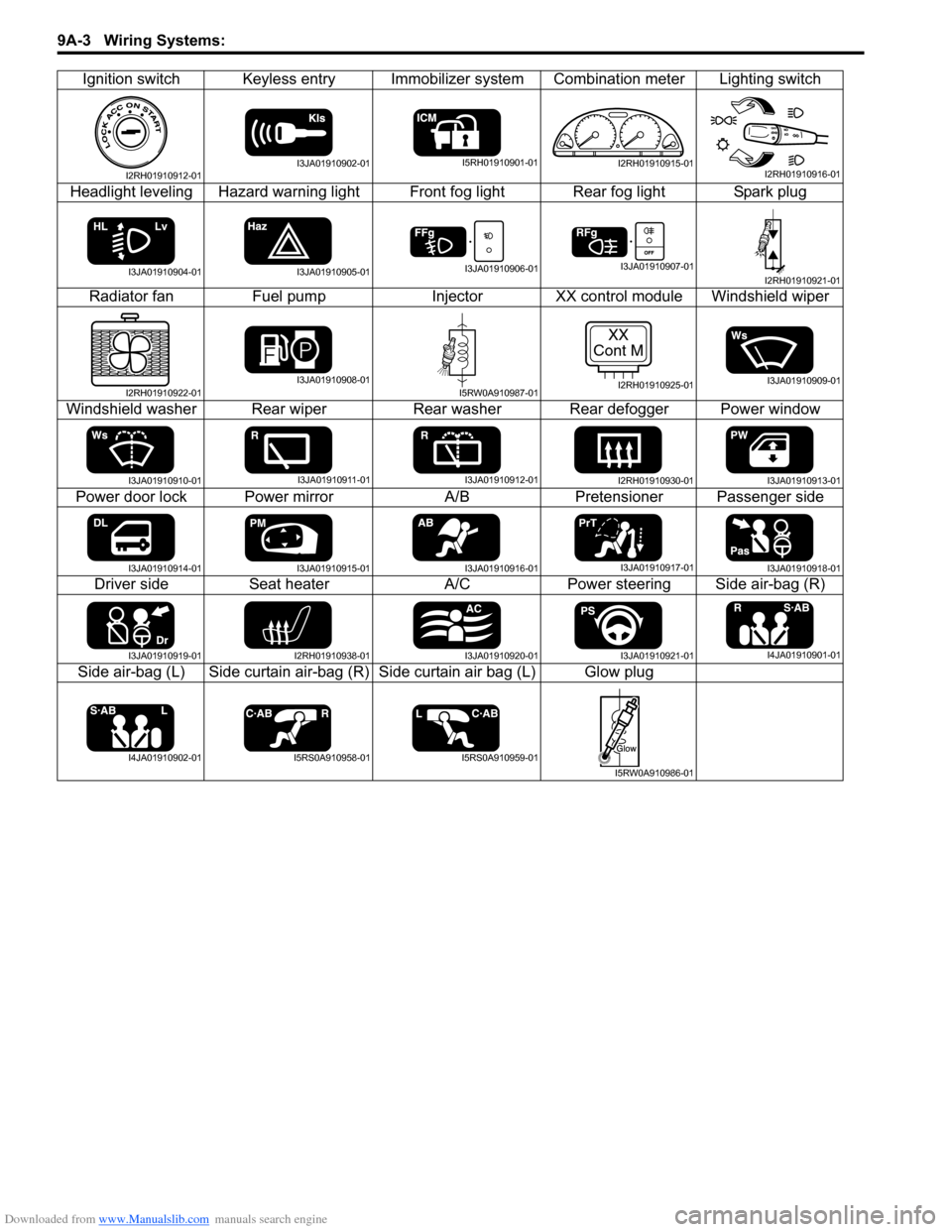
Downloaded from www.Manualslib.com manuals search engine 9A-3 Wiring Systems:
Ignition switch Keyless entry Immobilizer system Combination meter Lighting switch
Headlight leveling Hazard warning light Front fog light Rear fog light Spark plug
Radiator fan Fuel pump Injector XX control module Windshield wiper
Windshield washer Rear wiper Rear washer Rear defogger Power window
Power door lock Power mirror A/B Pretensioner Passenger side
Driver side Seat heater A/C Power steering Side air-bag (R)
Side air-bag (L) Side curtain air-bag (R) Side curtain air bag (L) Glow plug
I2RH01910912-01I3JA01910902-01I5RH01910901-01I2RH01910915-01I2RH01910916-01
I3JA01910904-01I3JA01910905-01I3JA01910906-01I3JA01910907-01I2RH01910921-01
I2RH01910922-01I3JA01910908-01I5RW0A910987-01
XX
Cont M
I2RH01910925-01I3JA01910909-01
I3JA01910910-01I3JA01910911-01I3JA01910912-01I2RH01910930-01I3JA01910913-01
I3JA01910914-01I3JA01910915-01I3JA01910916-01I3JA01910917-01I3JA01910918-01
I3JA01910919-01I2RH01910938-01I3JA01910920-01I3JA01910921-01I4JA01910901-01
I4JA01910902-01I5RS0A910958-01I5RS0A910959-01
I5RW0A910986-01
Page 1186 of 1556

Downloaded from www.Manualslib.com manuals search engine 9A-19 Wiring Systems:
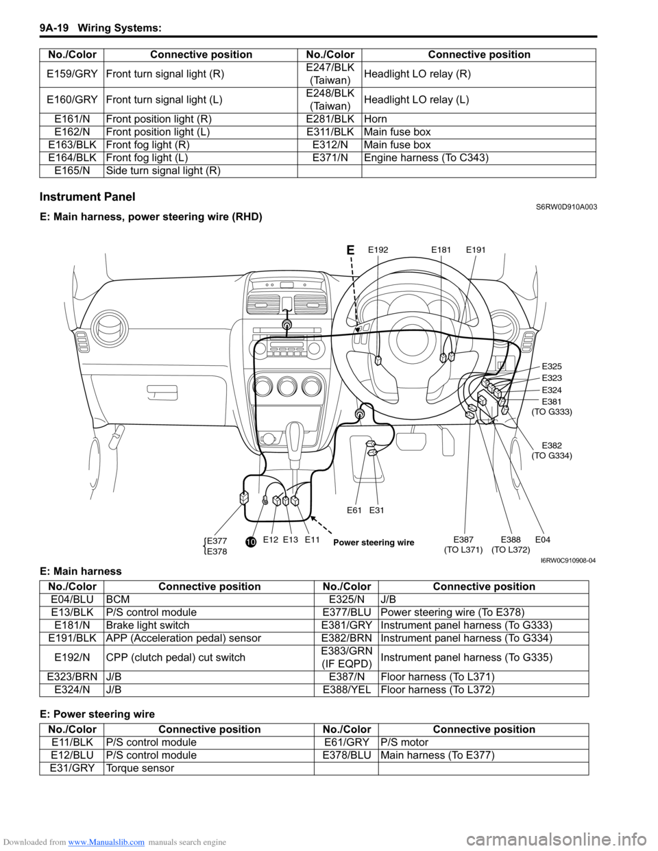
Instrument PanelS6RW0D910A003
E: Main harness, power steering wire (RHD)
E: Main harness
E: Power steering wireE159/GRY Front turn signal light (R)E247/BLK
(Taiwan)Headlight LO relay (R)
E160/GRY Front turn signal light (L)E248/BLK
(Taiwan)Headlight LO relay (L)
E161/N Front position light (R) E281/BLK Horn
E162/N Front position light (L) E311/BLK Main fuse box
E163/BLK Front fog light (R) E312/N Main fuse box
E164/BLK Front fog light (L) E371/N Engine harness (To C343)
E165/N Side turn signal light (R) No./Color Connective position No./Color Connective position
E12E13E11E387
(TO L371)E04E388
(TO L372)
E31E61
E377
E378
E325
E323
E324
E381
(TO G333)
E382
(TO G334)
E191E181E192
10
Power steering wire
E
I6RW0C910908-04
No./Color Connective position No./Color Connective position
E04/BLU BCM E325/N J/B
E13/BLK P/S control module E377/BLU Power steering wire (To E378)
E181/N Brake light switch E381/GRY Instrument panel harness (To G333)
E191/BLK APP (Acceleration pedal) sensor E382/BRN Instrument panel harness (To G334)
E192/N CPP (clutch pedal) cut switchE383/GRN
(IF EQPD)Instrument panel harness (To G335)
E323/BRN J/B E387/N Floor harness (To L371)
E324/N J/B E388/YEL Floor harness (To L372)
No./Color Connective position No./Color Connective position
E11/BLK P/S control module E61/GRY P/S motor
E12/BLU P/S control module E378/BLU Main harness (To E377)
E31/GRY Torque sensor