Page 1223 of 1556
Downloaded from www.Manualslib.com manuals search engine Wiring Systems: 9A-56
BCM (J/B side connector)
3
4
1
25
15 14 12
13 10
11 9 8 67
17
16182122 19
20
23
1234578 116
12 91034 652 1
G271 G273
G272
10
11 12 13 14 15 16 17 18 19123456789
20
345612L312
23414
3
561214 11
10
157 2 11316 9 8 6
5 4 3
2
1
7
11 10
9 8
15
14 13
1216
L313
L315 E325
2 1
12 34 5 6 78 9
15 16 17 18 11 10 12 13 14 1
234
5
678 910
E323
L314 E324
E323 E325E324 BCM G272G271 G273 L312 L313 L314 L315J/B
9
3
3
4
(Continued)
GND (IP) POWER GND
GND
SIGNAL
GND (FL)SIGNAL
GND (IP)
4
4
10
ST
ST RLY COIL
ST SIG
10A33
Individual circuit fuse box No.2
(In J/B)
7
6
BLOWER FAN
HTR HTR FUSEIG2 SIG
10A35
3 1
5
4
2
Connector No. / Terminal No.
56
I6RW0C910932-01
Page 1280 of 1556
Downloaded from www.Manualslib.com manuals search engine 9A-113 Wiring Systems:
D-3 Front Fog Light System Circuit Diagram (Except Taiwan)S6RW0D910E052
FR
FOG
(R) (L)
2
E1641
2
E1631
20A
14
Relay
Switch
3
E2342
14
WHT/GRNGRY/RED
LT GRN
BLK
BLKBLK
LT GRNLT GRN
1
D
DG334
E382
FREEIG LOAD E Il Ile
TERMINAL
POSITION
PUSH
6 7
4
8
G306
G151
RED/YEL
RED/YELGRY/REDRED/YEL
RED/YEL
11
BLK
BLK
RED/BLU
RED/BLU
5
J/C
B
BG309
J/C
A
A
C
CG306
J/C
BLK
BLK
RY"D-4"
BLKBLK
BLK
14
Individual circuit
fuse box (No.1)
9
BLK
7I6RW0C910983-01
Page 1281 of 1556
Downloaded from www.Manualslib.com manuals search engine Wiring Systems: 9A-114
D-3 Front Fog Light System Circuit Diagram (Taiwan)S6RW0D910E024
FR
FOG
(R) (L)
2
E1641
2
E1631
20A
14
Relay
Switch
3
E2342
14
WHT/GRNRED/YEL
RED/YEL
LT GRN
BLK
BLKBLK
LT GRNLT GRN
14
D
DG333
E381
13E381
G333
FREEIG LOAD E Il Ile
TERMINAL
POSITION
PUSH
7 6
4
8
G306
G151
RED/YEL
RED/YELGRY/REDRED/YEL
RED/YEL
11
BLK/YEL
BLK/YEL
5
J/C
B
BG309
J/C
A
AG306
J/C J/B
BLK
BLK
BLK
BLK
RY"D-4"GR
B
"A-8"
BLKBLK
BLK
14
Individual circuit
fuse box (No.1)
9
BLK
7
BCM
"A-8"
BCM
I6RW0C910982-01
Page 1298 of 1556
Downloaded from www.Manualslib.com manuals search engine 9A-131 Wiring Systems:
F-1 Air-Bag System Circuit Diagram (4ch)S6RW0D910E032
2
ORN
Y
A/B
SDM
L04
J/B
15AA/B
27
RED
L313
BCM
15
BLK
1
15ADOME
37
WHT/RED
G2715
E388
L3721G349
L3992
PNK/BLK
E40
Forward sensor
1 2
Contact
coil
G347
S172
L377
G3442L399
G34911
L28312S121
YEL/RED
GRN
12
21
YEL/RED
L285 G25912
4
38
75
69
10 2832 27
37
5051
2
"A-8"
L378
G345
ORN
PNK/BLKYEL
YEL
GRN/RED
GRN/REDGRNGRN/ORNGRN/YEL
BLU/RED
BLU/REDBLU/ORNBLU/YEL
L3134
G27213
J/B J/B
"C-3"YB
YEL/BLK
YEL/BLK
J/B side connector (BCM)
Except M16A engine M/T
M16A engine M/T
Except Taiwan
Taiwan A
B
E
D
2 12 1
BCDE
Check terminal
J/C
G308B
B
5
4
C
51114
E382
G33419
C343
E3718
BLK/ORN
BLK/ORNBLK/ORN
7
BLU
PPL/WHT
PPL/WHT
BLU
PPL/WHT
J/C IF EQPD
G308A
A
L313
G043
5
J/CJ/B
G309B
B
DLC
16
WHT
WHT/RED
RED
RW
PW
PW
"A-8"
14 6
BCM
BCM
(CAN)
G2114
BLKBLK
BLK
E
Y"A-8"
D
8A
I6RW0C910A00-01
Page 1300 of 1556
Downloaded from www.Manualslib.com manuals search engine 9A-133 Wiring Systems:
Q102
Q10312
212220
19
BLK/YELBRN/YELYEL/GRNYEL/BLU
BLK/YELBRN/YELYEL/GRNYEL/BLU
12
L395
Q132
1 2
2
454446
47
sensorsensor
LT GRNWHT/GRNWHT/REDLT GRN/BLK
1
2
ORN
YB
E388
L3721
PNK/BLK
E40
Forward sensor
Check terminal
1 2
250
51
ORN
PNK/BLKYEL/BLK
YEL/BLK
"C-3"
J/B
G272
L31313
4
Q105Q10412
A/B
SDM
131412
11
BRN/WHTBRN
12
GRY/REDGRY
BLUBLKBLUBLK
1212L384
Q133L385
Q134
L28512
910
BLU/ORNBLU/YEL
L04
L28312
87
GRN/ORNGRN/YEL
J/B side connector (BCM)
Except M16A engine M/T
M16A engine M/T
RHD
LHD ABCDE
1
3DE4
2DE3
1DE2
4DE
L36
L35D
EE
EL35
L36D
E
sensorsensor
DD
I6RW0D910923-01
Page 1320 of 1556

Downloaded from www.Manualslib.com manuals search engine 9B-1 Lighting Systems:
Body, Cab and Accessories
Lighting Systems
Precautions
Precautions for Discharge Headlight Service (If Equipped)S6RW0D9200001
WARNING!
• Do not touch igniter or ballast when lighting switch is at “HEAD” position to avoid possible electric
shock.
• Do not measure voltage or resistance with tester connected to output connector of ballast or igniter
to avoid possible electric shock.
• Do not perform work where exposed to water including rain or with wet hands to avoid possible
electric shock.
• Disassembling igniter or ballast is strictly prohibited as it may cause an electric shock.
• Before inspecting or repairing discharge headlight or its peripheral parts, make sure that lighting
switch is at OFF position and battery is disconnected at negative terminal to avoid possible
electrical shock.
• Do not set lighting switch to “HEAD” position with connector disconnected or any part removed to
avoid possible electric shock.
• Do not touch glass surface of headlight bulb. Oil or grease attached on it may not only make bulb
service life shorter but also cause bulb to burst when lighting switch is turned on.
• Mercury, metal iodide and xenon gas are sealed in discharge headlight bulb. Be sure to dispose of
used discharge headlight bulb properly according to applicable rules or regulations.
Precautions in Diagnosing Troubles (Headlight Auto Leveling System)S6RW0D9200002
• Be sure to read “Air Bag Warning in Section 00” before inspection and observe what is written there.
• Replacement of height sensor and headlight leveling control module. When height sensor and/or headlight leveling
control module is replaced with new one, perform initialization of headlight auto leveling system according to
“Initialization of Headlight Auto Leveling System”.
General Description
Discharge Headlight Description (If Equipped)S6RW0D9201001
Discharge headlight provides more brightness and consumes less electricity as compared with the conventional
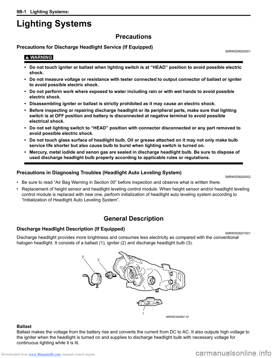
halogen headlight. It consists of a ballast (1), igniter (2) and discharge headlight bulb (3).
Ballast
Ballast makes the voltage from the battery rise and converts the current from DC to AC. It also outputs high voltage to
the igniter when the headlight is turned on and supplies to discharge headlight bulb with necessary voltage for
continuous lighting while it is lit.
2
1 3
I6RW0C920001-01
Page 1333 of 1556

Downloaded from www.Manualslib.com manuals search engine Lighting Systems: 9B-14
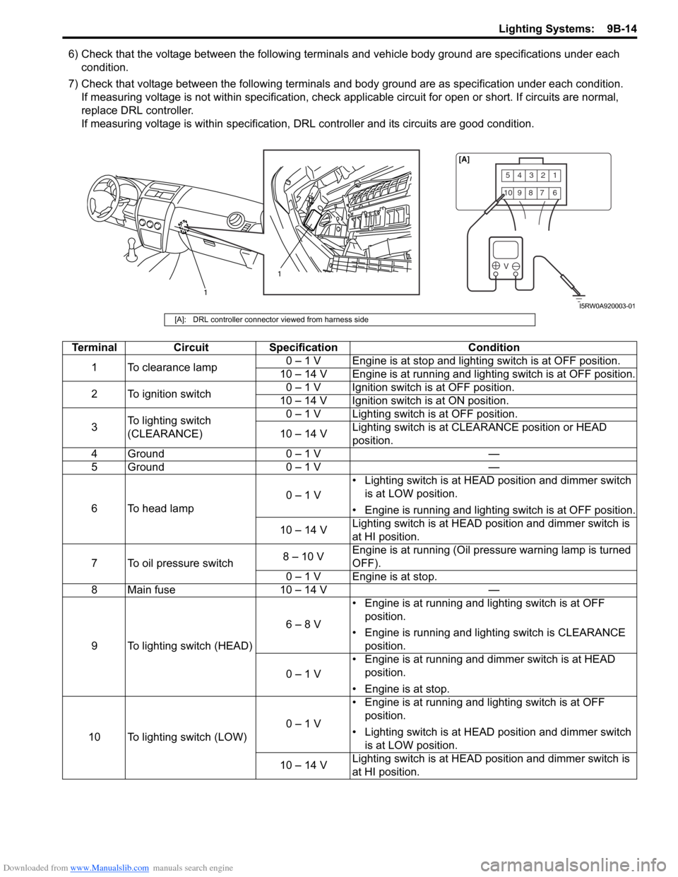
6) Check that the voltage between the following terminals and vehicle body ground are specifications under each
condition.
7) Check that voltage between the following terminals and body ground are as specification under each condition.
If measuring voltage is not within specification, check applicable circuit for open or short. If circuits are normal,
replace DRL controller.
If measuring voltage is within specification, DRL controller and its circuits are good condition.
54321
10987 6
V
1
1[A]
I5RW0A920003-01
[A]: DRL controller connector viewed from harness side
Terminal Circuit Specification Condition
1 To clearance lamp0 – 1 V Engine is at stop and lighting switch is at OFF position.
10 – 14 V Engine is at running and lighting switch is at OFF position.
2 To ignition switch0 – 1 V Ignition switch is at OFF position.
10 – 14 V Ignition switch is at ON position.
3To lighting switch
(CLEARANCE)0 – 1 V Lighting switch is at OFF position.
10 – 14 VLighting switch is at CLEARANCE position or HEAD
position.
4 Ground 0 – 1 V —
5 Ground 0 – 1 V —
6 To head lamp0 – 1 V• Lighting switch is at HEAD position and dimmer switch
is at LOW position.
• Engine is running and lighting switch is at OFF position.
10 – 14 VLighting switch is at HEAD position and dimmer switch is
at HI position.
7 To oil pressure switch8 – 10 VEngine is at running (Oil pressure warning lamp is turned
OFF).
0 – 1 V Engine is at stop.
8 Main fuse 10 – 14 V —
9 To lighting switch (HEAD)6 – 8 V• Engine is at running and lighting switch is at OFF
position.
• Engine is running and lighting switch is CLEARANCE
position.
0 – 1 V• Engine is at running and dimmer switch is at HEAD
position.
• Engine is at stop.
10 To lighting switch (LOW)0 – 1 V• Engine is at running and lighting switch is at OFF
position.
• Lighting switch is at HEAD position and dimmer switch
is at LOW position.
10 – 14 VLighting switch is at HEAD position and dimmer switch is
at HI position.
Page 1334 of 1556

Downloaded from www.Manualslib.com manuals search engine 9B-15 Lighting Systems:
Auto-On Headlight Operation Inspection (If
Equipped)
S6RW0D9204021
1) Turn ignition switch to ON position and then turn
lighting switch to “AUTO” position.
2) Check headlights for operation as follows. If
headlights do not turn ON or OFF, go to “Inspection
of Auto-On Headlight Controller and Its Circuit (If
Equipped)”.
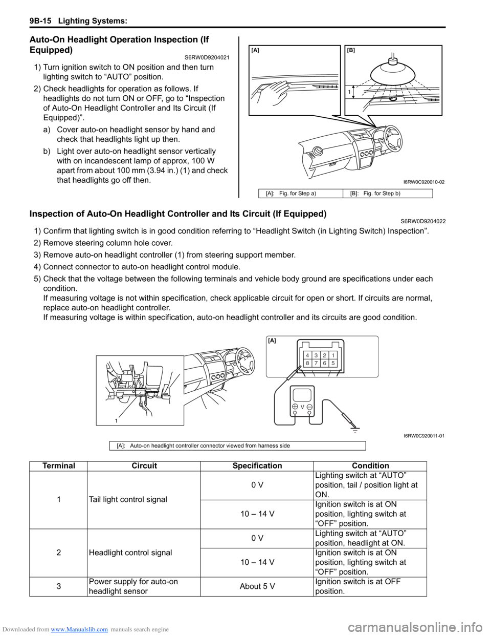
a) Cover auto-on headlight sensor by hand and
check that headlights light up then.
b) Light over auto-on headlight sensor vertically
with on incandescent lamp of approx, 100 W
apart from about 100 mm (3.94 in.) (1) and check
that headlights go off then.
Inspection of Auto-On Headlight Controller and Its Circuit (If Equipped)S6RW0D9204022
1) Confirm that lighting switch is in good condition referring to “Headlight Switch (in Lighting Switch) Inspection”.
2) Remove steering column hole cover.
3) Remove auto-on headlight controller (1) from steering support member.
4) Connect connector to auto-on headlight control module.
5) Check that the voltage between the following terminals and vehicle body ground are specifications under each
condition.
If measuring voltage is not within specification, check applicable circuit for open or short. If circuits are normal,
replace auto-on headlight controller.
If measuring voltage is within specification, auto-on headlight controller and its circuits are good condition.
[A]: Fig. for Step a) [B]: Fig. for Step b)
[A] [B]
1
I6RW0C920010-02
1
4321
8765
V
[A]
I6RW0C920011-01
[A]: Auto-on headlight controller connector viewed from harness side
Terminal Circuit Specification Condition
1 Tail light control signal0 VLighting switch at “AUTO”
position, tail / position light at
ON.
10 – 14 VIgnition switch is at ON
position, lighting switch at
“OFF” position.
2 Headlight control signal0 VLighting switch at “AUTO”
position, headlight at ON.
10 – 14 VIgnition switch is at ON
position, lighting switch at
“OFF” position.
3Power supply for auto-on
headlight sensorAbout 5 VIgnition switch is at OFF
position.