2006 SUZUKI SX4 terminal
[x] Cancel search: terminalPage 1158 of 1556
Downloaded from www.Manualslib.com manuals search engine 8B-119 Air Bag System:
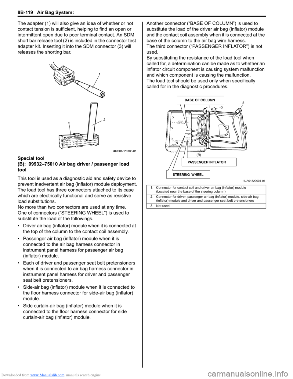
The adapter (1) will also give an idea of whether or not
contact tension is sufficient, helping to find an open or
intermittent open due to poor terminal contact. An SDM
short bar release tool (2) is included in the connector test
adapter kit. Inserting it into the SDM connector (3) will
releases the shorting bar.
Special tool
(B): 09932–75010 Air bag driver / passenger load
tool
This tool is used as a diagnostic aid and safety device to
prevent inadvertent air bag (inflator) module deployment.
The load tool has three connectors attached to its case
which are electrically functional and serve as resistive
load substitutions.
No more than two connectors are used at any time.
One of connectors (“STEERING WHEEL”) is used to
substitute the load of the followings.
• Driver air bag (inflator) module when it is connected at
the top of the column to the contact coil assembly.
• Passenger air bag (inflator) module when it is
connected to the air bag harness connector in
instrument panel harness for passenger air bag
(inflator) module.
• Each of driver and passenger seat belt pretensioners
when it is connected to air bag harness connector in
instrument panel harness for driver and passenger
seat belt pretensioners.
• Side-air bag (inflator) module when it is connected to
the floor harness connector for side-air bag (inflator)
module.
• Side curtain-air bag (inflator) module when it is
connected to the floor harness connector for side
curtain-air bag (inflator) module.Another connector (“BASE OF COLUMN”) is used to
substitute the load of the driver air bag (inflator) module
and the contact coil assembly when it is connected at the
base of the column to the air bag wire harness.
The third connector (“PASSENGER INFLATOR”) is not
used.
By substituting the resistance of the load tool when
called for, a determination can be made as to whether an
inflator circuit component is causing system malfunction
and which component is causing the malfunction.
The load tool should be used only when specifically
called for in the diagnostic procedures.
1
2
3
I4RS0A820108-01
1. Connector for contact coil and driver air bag (inflator) module
(Located near the base of the steering column)
2. Connector for driver, passenger air bag (inflator) module, side-air bag
(inflator) module and driver and passenger seat belt pretensioners
3. Not used
I1JA01820004-01
Page 1161 of 1556
Downloaded from www.Manualslib.com manuals search engine Table of Contents 9- i
9
Section 9
CONTENTS
Body, Cab and Accessories
Precautions ................................................. 9-1
Precautions............................................................. 9-1
Precautions on Body, Cab and Accessories ......... 9-1
Precautions for Body Service ................................ 9-1
Fastener Caution for Body Service ....................... 9-1
Wiring Systems........................................ 9A-1
Precautions........................................................... 9A-1
Cautions in Body Electrical System Servicing..... 9A-1
General Description ............................................. 9A-1
Abbreviations ...................................................... 9A-1
Wire / Connector Color Symbols ......................... 9A-1
Symbols and Marks ............................................ 9A-2
How to Read Connector Layout Diagram ........... 9A-4
How to Read Connector Codes and Terminal
Nos.................................................................... 9A-5
How to Read Ground Point ................................. 9A-8
How to Read Power Supply Diagram.................. 9A-9
How to Read System Circuit Diagram................. 9A-9
Connector Layout Diagram ............................... 9A-11
Connector Layout Diagram ............................... 9A-11
Engine Compartment ........................................ 9A-11
Instrument Panel ............................................... 9A-19
Door, Roof......................................................... 9A-25
Floor .................................................................. 9A-28
Rear .................................................................. 9A-32
Ground Point ...................................................... 9A-33
Ground (earth) Point ......................................... 9A-33
Power Supply Diagram ...................................... 9A-34
Power Supply Diagram ..................................... 9A-34
Fuses and the Protected Parts ......................... 9A-36
Fuses in Main Fuse Box ................................... 9A-36
Individual Circuit Fuse Box No. 1 ...................... 9A-37
Individual Circuit Fuse Box No. 2 (In J/B
(Except Taiwan)) ............................................. 9A-38
Individual Circuit Fuse Box No. 2 (In J/B
(Taiwan)) ......................................................... 9A-40
Junction Block (J/B) Connector / Fuse Layout .. 9A-42
Junction Block Inner Circuit (Overview
(Except Taiwan)) ............................................. 9A-43
Junction Block Inner Circuit (Detail (Except
Taiwan)) .......................................................... 9A-45
Junction Block Inner Circuit (Overview
(Taiwan)) ......................................................... 9A-50Junction Block Inner Circuit (Detail (Taiwan)) ... 9A-52
System Circuit Diagram.....................................9A-57
System Circuit Diagram .................................... 9A-57
A-1 Cranking System Circuit Diagram .............. 9A-58
A-2 Charging System Circuit Diagram .............. 9A-59
A-3 Ignition System Circuit Diagram (M15A
engine, M16A engine) ..................................... 9A-60
A-3 Ignition System Circuit Diagram (J20A
engine) ............................................................ 9A-61
A-4 Cooling System Circuit Diagram (M15A
engine, M16A engine) ..................................... 9A-62
A-4 Cooling System Circuit Diagram (J20A
engine) ............................................................ 9A-63
A-5 Engine and A/C Control System Circuit
Diagram (M15A engine) .................................. 9A-64
A-5 Engine and A/C Control System Circuit
Diagram (M16A engine) .................................. 9A-68
A-5 Engine and A/C Control System Circuit
Diagram (J20A engine) ................................... 9A-72
A-6 A/T Control System Circuit Diagram........... 9A-76
A-7 Immobilizer System Circuit Diagram .......... 9A-78
A-8 Body Control System Circuit Diagram
(Except Taiwan) .............................................. 9A-79
A-8 Body Control System Circuit Diagram
(Taiwan) .......................................................... 9A-83
A-10 4WD Control System (Except Taiwan) ..... 9A-87
B-1 Windshield Wiper and Washer Circuit
Diagram........................................................... 9A-88
B-2 Rear Wiper and Washer Circuit Diagram
(Except Taiwan) .............................................. 9A-89
B-2 Rear Wiper and Washer Circuit Diagram
(Taiwan) .......................................................... 9A-90
B-3 Rear Defogger Circuit Diagram (Except
Taiwan) ........................................................... 9A-91
B-3 Rear Defogger Circuit Diagram (Taiwan) ... 9A-92
B-4 Power Window Circuit Diagram .................. 9A-93
B-5 Power Door Lock Circuit Diagram (Except
Taiwan) ........................................................... 9A-95
B-5 Power Door Lock Circuit Diagram
(Taiwan) .......................................................... 9A-97
B-6 Power Mirror Circuit Diagram (Except
Taiwan) ........................................................... 9A-99
B-6 Power Mirror Circuit Diagram (Taiwan) .... 9A-100
B-7 Horn Circuit Diagram ................................ 9A-101
B-8 Seat Heater Circuit Diagram..................... 9A-102
Page 1169 of 1556
Downloaded from www.Manualslib.com manuals search engine Wiring Systems: 9A-2
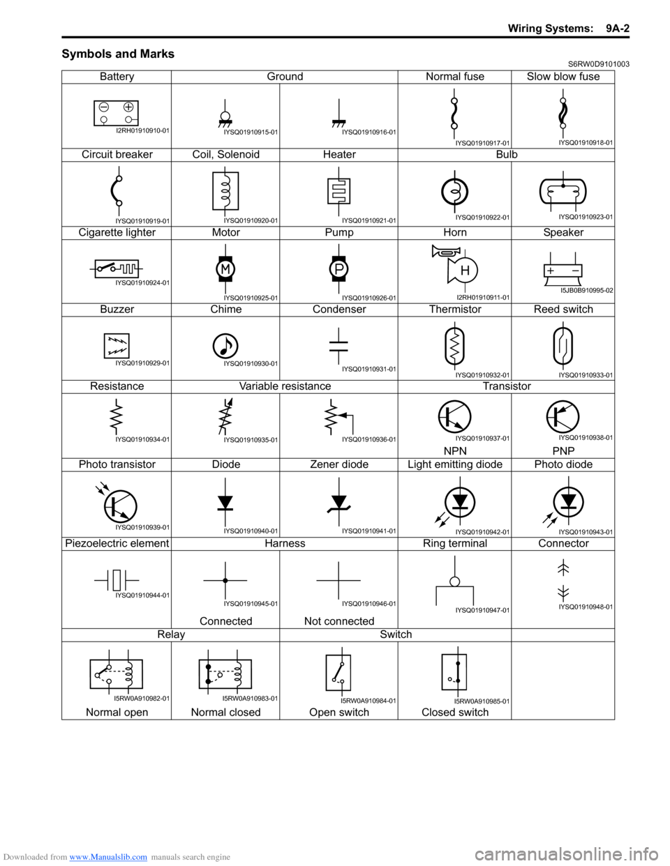
Symbols and MarksS6RW0D9101003
Battery Ground Normal fuse Slow blow fuse
Circuit breaker Coil, Solenoid Heater Bulb
Cigarette lighter Motor Pump Horn Speaker
Buzzer Chime Condenser Thermistor Reed switch
Resistance Variable resistance Transistor
NPN PNP
Photo transistor Diode Zener diode Light emitting diode Photo diode
Piezoelectric element Harness Ring terminal Connector
Connected Not connected
Relay Switch
Normal open Normal closed Open switch Closed switch
I2RH01910910-01IYSQ01910915-01IYSQ01910916-01
IYSQ01910917-01IYSQ01910918-01
IYSQ01910919-01IYSQ01910920-01IYSQ01910921-01IYSQ01910922-01IYSQ01910923-01
IYSQ01910924-01
IYSQ01910925-01IYSQ01910926-01
H
I2RH01910911-01I5JB0B910995-02
IYSQ01910929-01IYSQ01910930-01IYSQ01910931-01IYSQ01910932-01IYSQ01910933-01
IYSQ01910934-01IYSQ01910935-01IYSQ01910936-01IYSQ01910937-01IYSQ01910938-01
IYSQ01910939-01IYSQ01910940-01IYSQ01910941-01IYSQ01910942-01IYSQ01910943-01
IYSQ01910944-01IYSQ01910945-01IYSQ01910946-01IYSQ01910947-01IYSQ01910948-01
I5RW0A910982-01I5RW0A910983-01I5RW0A910984-01I5RW0A910985-01
Page 1172 of 1556
Downloaded from www.Manualslib.com manuals search engine 9A-5 Wiring Systems:
How to Read Connector Codes and Terminal Nos.S6RW0D9101005
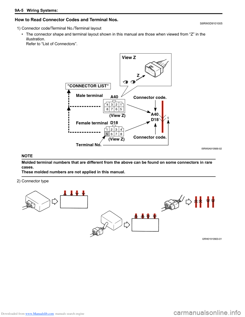
1) Connector code/Terminal No./Terminal layout
• The connector shape and terminal layout shown in this manual are those when viewed from “Z” in the
illustration.
Refer to “List of Connectors”.
NOTE
Molded terminal numbers that are different from the above can be found on some connectors in rare
cases.
These molded numbers are not applied in this manual.
2) Connector type
A40
(View Z)
(View Z)
1
123 4
567 82 3 4
5 6 7 8
D185
D18A40
Connector code.
Connector code.
Terminal No.
"CONNECTOR LIST"
Male terminal
Female terminalZ
View Z
I5RW0A910988-02
I2RH01910903-01
Page 1173 of 1556
Downloaded from www.Manualslib.com manuals search engine Wiring Systems: 9A-6
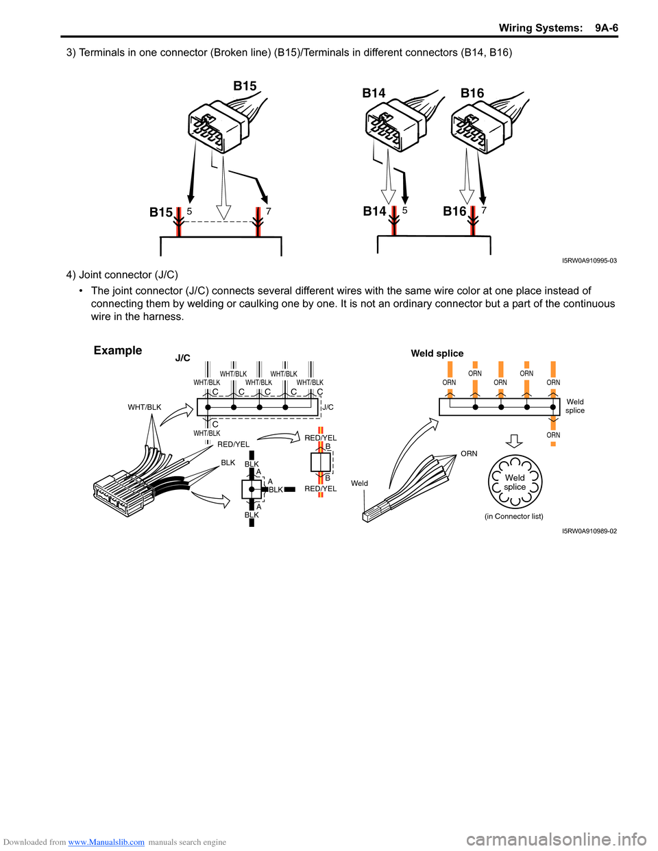
3) Terminals in one connector (Broken line) (B15)/Terminals in different connectors (B14, B16)
4) Joint connector (J/C)
• The joint connector (J/C) connects several different wires with the same wire color at one place instead of
connecting them by welding or caulking one by one. It is not an ordinary connector but a part of the continuous
wire in the harness.
B15B15
B14 B1657B14 B1657
I5RW0A910995-03
BLK
BLK
A
A
AB
B RED/YEL
WeldORN WHT/BLK
J/CWeld splice
BLKBLK
RED/YEL
RED/YEL
WHT/BLK
WHT/BLK
WHT/BLKWHT/BLKWHT/BLKWHT/BLKC
CCCCCWeld
splice
(in Connector list) J/C
ORNORNORNORNORN
ORN
Weld
splice
Example
I5RW0A910989-02
Page 1174 of 1556
Downloaded from www.Manualslib.com manuals search engine 9A-7 Wiring Systems:
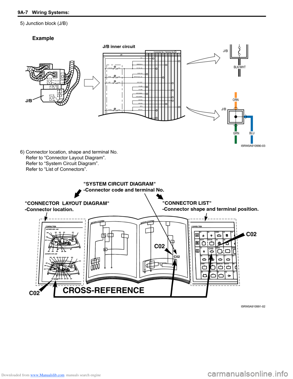
5) Junction block (J/B)
6) Connector location, shape and terminal No.
Refer to “Connector Layout Diagram”.
Refer to “System Circuit Diagram”.
Refer to “List of Connectors”.
IMMOBI IGIG1IG Coil, etcE39 E41E40 BCM G34G33 G32 K01 L04 L05 L06
IG Coil IG1
15A
MTR
10A
A/B
15A
2
65
13
J/BConnector No. / Terminal No.
BCM ;IG1
MTR Power, etc
A/B CONTK-LINE
K-LINE
A/B SIGNAL
A/B SIGNAL
A/B SIG
A/B SIG
IG Sig
10AEPS ATMTA
4
6
1
3
24
8
11
9
12
9
11
23
25
30
29
Example
J/B
J/B
ORN
GRNBLU
J/B
J/B inner circuit
BLK/WHT
I5RW0A910990-03
"SYSTEM CIRCUIT DIAGRAM"
-Connector code and terminal No.
"CONNECTOR LAYOUT DIAGRAM"
-Connector location.
CROSS-REFERENCE
"CONNECTOR LIST"
-Connector shape and terminal position.
C02
C02C02
C02
C02
C02
I5RW0A910991-02
Page 1177 of 1556
![SUZUKI SX4 2006 1.G Service Workshop Manual Downloaded from www.Manualslib.com manuals search engine Wiring Systems: 9A-10
[D]: Terminals-in-one-connector mark
[E]: Wire color
[F]: Shield wire
[G]: Ground point
[H]: “From” or “To” (Wit SUZUKI SX4 2006 1.G Service Workshop Manual Downloaded from www.Manualslib.com manuals search engine Wiring Systems: 9A-10
[D]: Terminals-in-one-connector mark
[E]: Wire color
[F]: Shield wire
[G]: Ground point
[H]: “From” or “To” (Wit](/manual-img/20/7612/w960_7612-1176.png)
Downloaded from www.Manualslib.com manuals search engine Wiring Systems: 9A-10
[D]: Terminals-in-one-connector mark
[E]: Wire color
[F]: Shield wire
[G]: Ground point
[H]: “From” or “To” (With ID letter (s))
[I]: Specification variation
The white arrow between A and B means “or”.
[J]: “From” (With ID letter (s))
[K] “To” (With ID letter (s))
[L]: Connector code
[M]: Terminal No.
[N]: Symbol mark
[O]: “SEE” mark
Switch
BLU
BLU
GRN/BLK
GRN/REDGRN/BLK
12
GRN
GRN
C262
1
BLK
5
BLK
2 1
C40
GRN/BLK
"XX"
Solenoid FuseFuse
3
15A
Main
relay
ON OFF
1
15A
6
20A
1
Sensor 1
2
8
BRN/RED
E521
2E521
BRN/RED
RED
2
BRN/REDBRN/RED
MotorM M
655
A
B
AB5
6
1
2
56464 4-DOOR
2-DOOR
2
C71
E03
E34
O06
C31
E19
[A]
[B]
[C]
[F]
[G]
[H] [D][I] [K] [L]
E3375E341
21
43E08
ORNWHTYEL
RED
YELYEL/REDGRN/RED
4
3
YEL
BLK/RED
ORN
GRN
GRN
BA
GRN
GRN
2
XX
Cont.M
[J]
[E]
[N] [O] [M]
GBGR
Y
Y
GB
P
3
4
2
3
L50 G20
1
GR
Y
BLK
BLK
GR
I5RW0A910994-02
Page 1212 of 1556
Downloaded from www.Manualslib.com manuals search engine 9A-45 Wiring Systems:
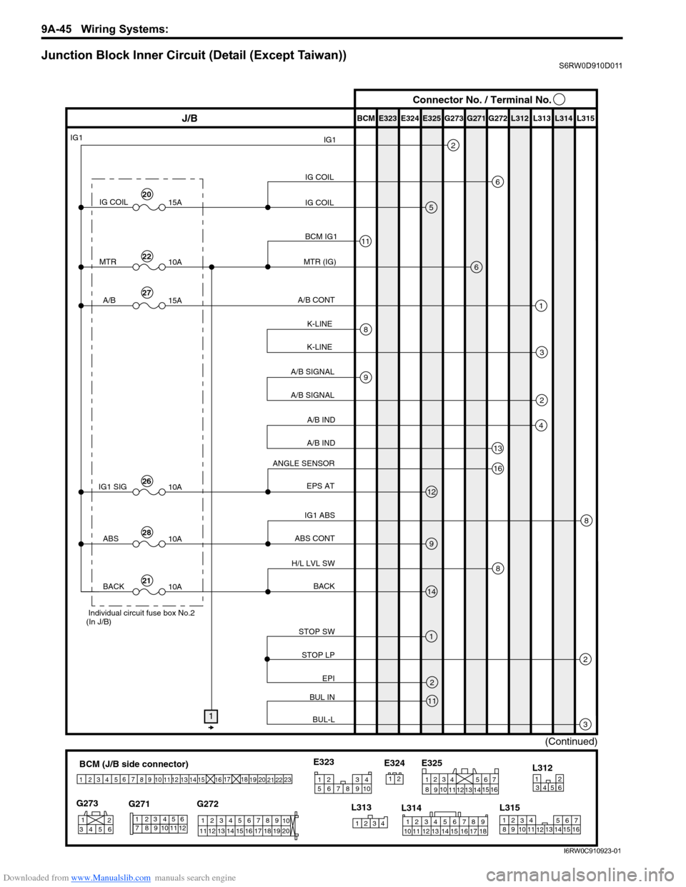
Junction Block Inner Circuit (Detail (Except Taiwan))S6RW0D910D011
BCM (J/B side connector)
3
4
1
25
15 14 12
13 10
11 9 8 67
17
16182122 19
20
23
1234578 116
12 91034 652 1
G271 G273
G272
10
11 12 13 14 15 16 17 18 19123456789
20
345612L312
23414
3
561214 11
10
157 2 11316 9 8 6
5 4 3
2
1
7
11 10
9 8
15
14 13
1216
L313
L315 E325
2 1
123456789
15 16 17 18 11 10 12 13 14 1
234
5
678 910
E323
L314 E324
IG COIL
IG COILIG1
E323 E325E324 BCM G272G271 G273 L312 L313 L314 L315
IG COIL IG1
15A
MTR
10A
A/B
15A
2
6
5
13
J/BConnector No. / Terminal No.
MTR (IG)
A/B CONT
A/B IND
A/B IND
IG1 SIG
10AEPS AT
ABS CONT
STOP SW
STOP LP
EPI
BUL IN
BUL-LBACK H/L LVL SW
BCM IG111
6
1
4
2
A/B SIGNAL
A/B SIGNAL9
3
K-LINE
K-LINE8
12
9
14
2
3
1
2
11
8
ABS
10A
BACK
10A
ANGLE SENSOR
IG1 ABS16
8
1
(Continued)
Individual circuit fuse box No.2
(In J/B)
20
22
27
26
28
21
I6RW0C910923-01