2006 SUZUKI SX4 sensor
[x] Cancel search: sensorPage 1004 of 1556

Downloaded from www.Manualslib.com manuals search engine 7B-64 Air Conditioning System: Automatic Type
DTC Troubleshooting
NOTE
• When DTC B1502, B1503, B1504 and B1511 are indicated together, it is possible that sensor ground
circuit is open.
• When DTC B1511 is indicated together, it is possible that position sensor power supply circuit is
open.
Step Action Yes No
1Was “Air Conditioning System Check” performed?Go to Step 2. Go to “Air Conditioning
System Check”.
2Wire harness check
1) Turn ignition switch to OFF position.
2) Disconnect connectors from air flow control actuator and
HVAC control module.
3) Check for proper connection to position sensor power
supply, signal and ground circuit terminals of air flow
control actuator and HVAC control module connectors.
4) If OK, check that position sensor of air flow control
actuator circuit is as follows.
• Wiring harness resistance of each position sensor
power supply, signal and ground circuit is less than 3
Ω
• Insulation resistance of each position sensor power
supply, signal and ground circuit is infinity between air
flow control actuator connector and vehicle body
ground
• Circuit voltage of each position sensor power supply,
signal and ground circuit is 0 - 1 V with ignition switch
turned ON
Are they in good condition?Go to Step 3. Position sensor power
supply, signal circuit
and/or ground circuit are
open, short or high
resistance.
3Position sensor of air flow control actuator power
supply voltage check
1) Connect connector to HVAC control module with ignition
switch turned OFF.
2) Turn ignition switch to ON position.
3) Measure voltage between.
• Position sensor power supply terminal and position
sensor ground terminal of air flow control actuator
connector
• Position sensor signal terminal and position sensor
ground terminal of air flow control actuator connector
Is voltage 4.5 – 5.5 V?Go to Step 4. Go to Step 5.
4Air flow control actuator check
1) Check position sensor of air flow control actuator for
performance referring to “Air Flow Control Actuator and
Its Circuit Inspection”.
Is it in good condition?Substitute a known-
good HVAC control
module and recheck.Replace air flow control
actuator.
Page 1005 of 1556
Downloaded from www.Manualslib.com manuals search engine Air Conditioning System: Automatic Type 7B-65
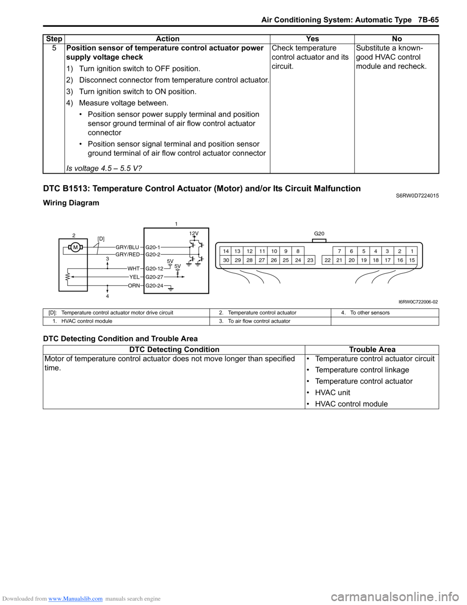
DTC B1513: Temperature Control Actuator (Motor) and/or Its Circuit MalfunctionS6RW0D7224015
Wiring Diagram
DTC Detecting Condition and Trouble Area5Position sensor of temperature control actuator power
supply voltage check
1) Turn ignition switch to OFF position.
2) Disconnect connector from temperature control actuator.
3) Turn ignition switch to ON position.
4) Measure voltage between.
• Position sensor power supply terminal and position
sensor ground terminal of air flow control actuator
connector
• Position sensor signal terminal and position sensor
ground terminal of air flow control actuator connector
Is voltage 4.5 – 5.5 V?Check temperature
control actuator and its
circuit.Substitute a known-
good HVAC control
module and recheck. Step Action Yes No
G20
1 2 3 4 5 6 7 8 9 10 11 12 13 14
15 16 17 18 19 20 21 24 23 22 25 26 27 28 29 30
GRY/BLUGRY/RED
5V5V
12V
ORN
WHT
YEL
G20-12
G20-27
G20-24
G20-1G20-2
2
[D]
3
41
I6RW0C722006-02
[D]: Temperature control actuator motor drive circuit 2. Temperature control actuator 4. To other sensors
1. HVAC control module 3. To air flow control actuator
DTC Detecting Condition Trouble Area
Motor of temperature control actuator does not move longer than specified
time.• Temperature control actuator circuit
• Temperature control linkage
• Temperature control actuator
• HVAC unit
• HVAC control module
Page 1006 of 1556
Downloaded from www.Manualslib.com manuals search engine 7B-66 Air Conditioning System: Automatic Type
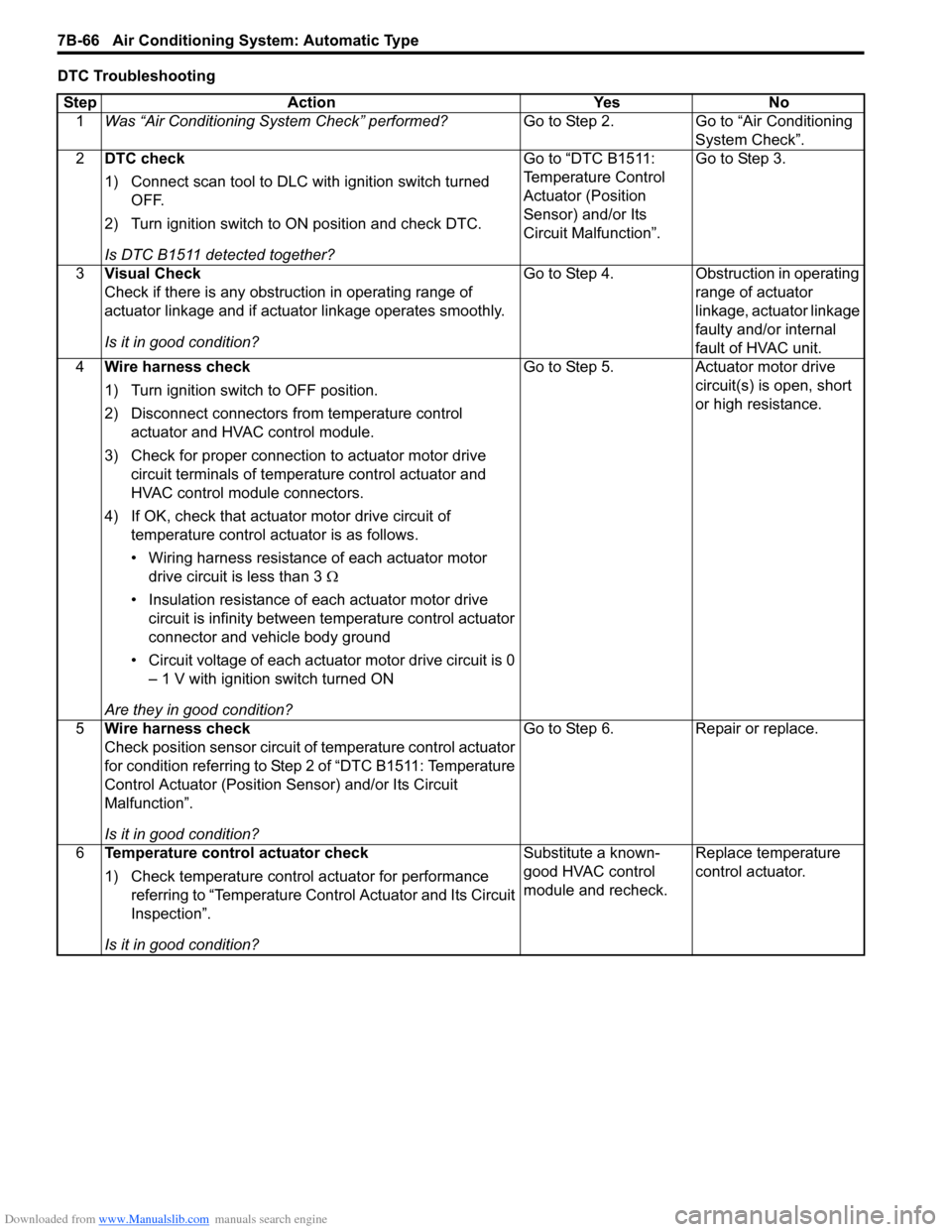
DTC Troubleshooting
Step Action Yes No
1Was “Air Conditioning System Check” performed?Go to Step 2. Go to “Air Conditioning
System Check”.
2DTC check
1) Connect scan tool to DLC with ignition switch turned
OFF.
2) Turn ignition switch to ON position and check DTC.
Is DTC B1511 detected together?Go to “DTC B1511:
Temperature Control
Actuator (Position
Sensor) and/or Its
Circuit Malfunction”.Go to Step 3.
3Visual Check
Check if there is any obstruction in operating range of
actuator linkage and if actuator linkage operates smoothly.
Is it in good condition?Go to Step 4. Obstruction in operating
range of actuator
linkage, actuator linkage
faulty and/or internal
fault of HVAC unit.
4Wire harness check
1) Turn ignition switch to OFF position.
2) Disconnect connectors from temperature control
actuator and HVAC control module.
3) Check for proper connection to actuator motor drive
circuit terminals of temperature control actuator and
HVAC control module connectors.
4) If OK, check that actuator motor drive circuit of
temperature control actuator is as follows.
• Wiring harness resistance of each actuator motor
drive circuit is less than 3 Ω
• Insulation resistance of each actuator motor drive
circuit is infinity between temperature control actuator
connector and vehicle body ground
• Circuit voltage of each actuator motor drive circuit is 0
– 1 V with ignition switch turned ON
Are they in good condition?Go to Step 5. Actuator motor drive
circuit(s) is open, short
or high resistance.
5Wire harness check
Check position sensor circuit of temperature control actuator
for condition referring to Step 2 of “DTC B1511: Temperature
Control Actuator (Position Sensor) and/or Its Circuit
Malfunction”.
Is it in good condition?Go to Step 6. Repair or replace.
6Temperature control actuator check
1) Check temperature control actuator for performance
referring to “Temperature Control Actuator and Its Circuit
Inspection”.
Is it in good condition?Substitute a known-
good HVAC control
module and recheck.Replace temperature
control actuator.
Page 1007 of 1556
Downloaded from www.Manualslib.com manuals search engine Air Conditioning System: Automatic Type 7B-67
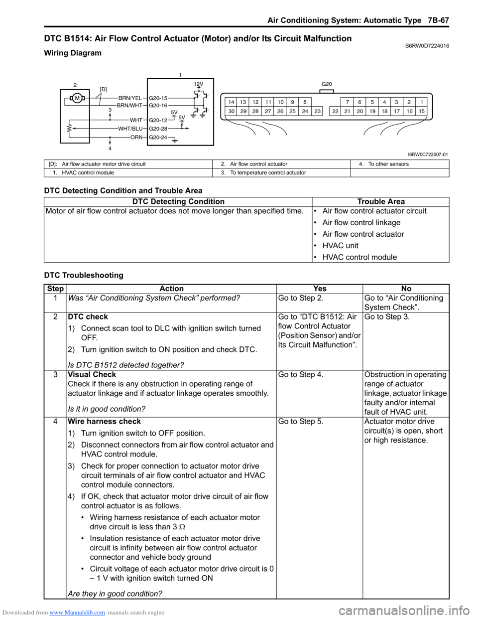
DTC B1514: Air Flow Control Actuator (Motor) and/or Its Circuit MalfunctionS6RW0D7224016
Wiring Diagram
DTC Detecting Condition and Trouble Area
DTC Troubleshooting
G20
1 2 3 4 5 6 7 8 9 10 11 12 13 14
15 16 17 18 19 20 21 24 23 22 25 26 27 28 29 30
BRN/YELBRN/WHT
5V5V
12V
ORN
WHTG20-12
G20-28
G20-24
G20-15G20-16
WHT/BLU 2
3
41
[D]
I6RW0C722007-01
[D]: Air flow actuator motor drive circuit 2. Air flow control actuator 4. To other sensors
1. HVAC control module 3. To temperature control actuator
DTC Detecting Condition Trouble Area
Motor of air flow control actuator does not move longer than specified time. • Air flow control actuator circuit
• Air flow control linkage
• Air flow control actuator
• HVAC unit
• HVAC control module
Step Action Yes No
1Was “Air Conditioning System Check” performed?Go to Step 2. Go to “Air Conditioning
System Check”.
2DTC check
1) Connect scan tool to DLC with ignition switch turned
OFF.
2) Turn ignition switch to ON position and check DTC.
Is DTC B1512 detected together?Go to “DTC B1512: Air
flow Control Actuator
(Position Sensor) and/or
Its Circuit Malfunction”.Go to Step 3.
3Visual Check
Check if there is any obstruction in operating range of
actuator linkage and if actuator linkage operates smoothly.
Is it in good condition?Go to Step 4. Obstruction in operating
range of actuator
linkage, actuator linkage
faulty and/or internal
fault of HVAC unit.
4Wire harness check
1) Turn ignition switch to OFF position.
2) Disconnect connectors from air flow control actuator and
HVAC control module.
3) Check for proper connection to actuator motor drive
circuit terminals of air flow control actuator and HVAC
control module connectors.
4) If OK, check that actuator motor drive circuit of air flow
control actuator is as follows.
• Wiring harness resistance of each actuator motor
drive circuit is less than 3 Ω
• Insulation resistance of each actuator motor drive
circuit is infinity between air flow control actuator
connector and vehicle body ground
• Circuit voltage of each actuator motor drive circuit is 0
– 1 V with ignition switch turned ON
Are they in good condition?Go to Step 5. Actuator motor drive
circuit(s) is open, short
or high resistance.
Page 1008 of 1556
Downloaded from www.Manualslib.com manuals search engine 7B-68 Air Conditioning System: Automatic Type
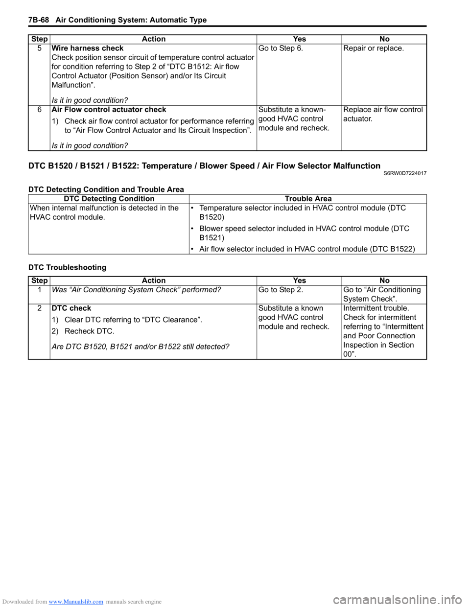
DTC B1520 / B1521 / B1522: Temperature / Blower Speed / Air Flow Selector MalfunctionS6RW0D7224017
DTC Detecting Condition and Trouble Area
DTC Troubleshooting5Wire harness check
Check position sensor circuit of temperature control actuator
for condition referring to Step 2 of “DTC B1512: Air flow
Control Actuator (Position Sensor) and/or Its Circuit
Malfunction”.
Is it in good condition?Go to Step 6. Repair or replace.
6Air Flow control actuator check
1) Check air flow control actuator for performance referring
to “Air Flow Control Actuator and Its Circuit Inspection”.
Is it in good condition?Substitute a known-
good HVAC control
module and recheck.Replace air flow control
actuator. Step Action Yes No
DTC Detecting Condition Trouble Area
When internal malfunction is detected in the
HVAC control module.• Temperature selector included in HVAC control module (DTC
B1520)
• Blower speed selector included in HVAC control module (DTC
B1521)
• Air flow selector included in HVAC control module (DTC B1522)
Step Action Yes No
1Was “Air Conditioning System Check” performed?Go to Step 2. Go to “Air Conditioning
System Check”.
2DTC check
1) Clear DTC referring to “DTC Clearance”.
2) Recheck DTC.
Are DTC B1520, B1521 and/or B1522 still detected?Substitute a known
good HVAC control
module and recheck.Intermittent trouble.
Check for intermittent
referring to “Intermittent
and Poor Connection
Inspection in Section
00”.
Page 1010 of 1556
Downloaded from www.Manualslib.com manuals search engine 7B-70 Air Conditioning System: Automatic Type
DTC B1546: A/C Refrigerant Pressure MalfunctionS6RW0D7224019
DTC Detecting Condition and Trouble Area
DTC Troubleshooting
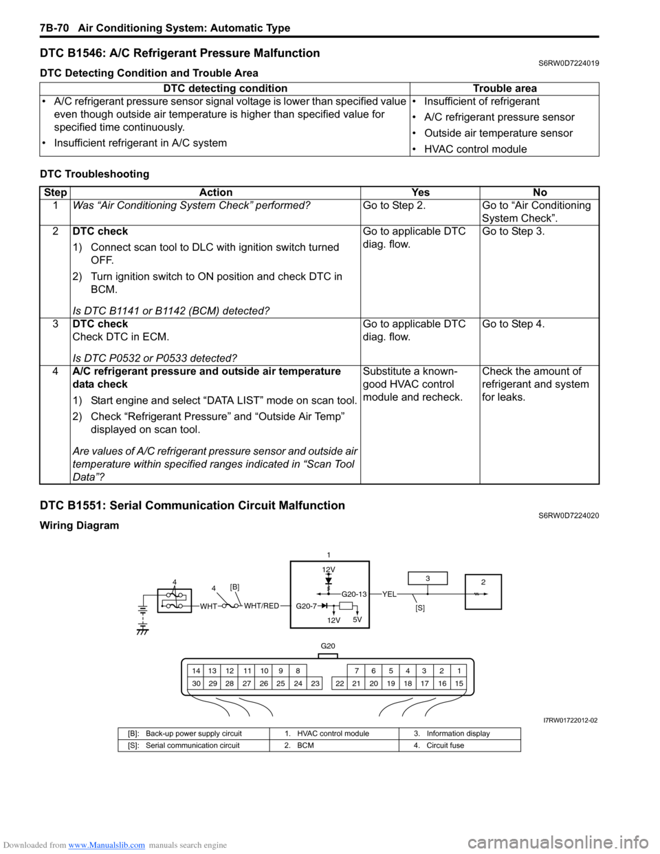
DTC B1551: Serial Communication Circuit MalfunctionS6RW0D7224020
Wiring DiagramDTC detecting condition Trouble area
• A/C refrigerant pressure sensor signal voltage is lower than specified value
even though outside air temperature is higher than specified value for
specified time continuously.
• Insufficient refrigerant in A/C system• Insufficient of refrigerant
• A/C refrigerant pressure sensor
• Outside air temperature sensor
• HVAC control module
Step Action Yes No
1Was “Air Conditioning System Check” performed?Go to Step 2. Go to “Air Conditioning
System Check”.
2DTC check
1) Connect scan tool to DLC with ignition switch turned
OFF.
2) Turn ignition switch to ON position and check DTC in
BCM.
Is DTC B1141 or B1142 (BCM) detected?Go to applicable DTC
diag. flow.Go to Step 3.
3DTC check
Check DTC in ECM.
Is DTC P0532 or P0533 detected?Go to applicable DTC
diag. flow.Go to Step 4.
4A/C refrigerant pressure and outside air temperature
data check
1) Start engine and select “DATA LIST” mode on scan tool.
2) Check “Refrigerant Pressure” and “Outside Air Temp”
displayed on scan tool.
Are values of A/C refrigerant pressure sensor and outside air
temperature within specified ranges indicated in “Scan Tool
Data”?Substitute a known-
good HVAC control
module and recheck.Check the amount of
refrigerant and system
for leaks.
12V
G20
G20-13YEL
1 2 3 4 5 6 7 8 9 10 11 12 13 14
15 16 17 18 19 20 21 24 23 22 25 26 27 28 29 30
1
2 3
[S]WHT/REDWHTG20-7
12V5V
[B]4 4
I7RW01722012-02
[B]: Back-up power supply circuit 1. HVAC control module 3. Information display
[S]: Serial communication circuit 2. BCM 4. Circuit fuse
Page 1012 of 1556
Downloaded from www.Manualslib.com manuals search engine 7B-72 Air Conditioning System: Automatic Type
DTC B1552: HVAC Control Module Check Sum ErrorS6RW0D7224021
DTC Detecting Condition and Trouble Area
DTC Troubleshooting
DTC B1553: CAN Communication Circuit MalfunctionS6RW0D7224022
DTC Detecting Condition and Trouble Area
DTC TroubleshootingDTC detecting condition Trouble area
Data received by HVAC control module from BCM is erroneous continuously. • BCM
• HVAC control module
Step Action Yes No
1Was “Air Conditioning System Check” performed?Go to Step 2. Go to “Air Conditioning
System Check”.
2Serial communication signal data check
1) Connect scan tool to DLC with ignition switch turned
OFF.
2) Start engine and select “DATA LIST” mode on scan tool.
3) Check “Refrigerant Pressure”, “Vehicle Speed”, “Coolant
Temp” and “Outside Air Temp” displayed on scan tool.
Are values of A/C refrigerant pressure sensor and outside air
temperature within specified ranges indicated in “Scan Tool
Data”?Intermittent trouble.
Check for intermittent
referring to “Intermittent
and Poor Connection
Inspection in Section
00”Substitute a known-
good HVAC control
module and recheck.
If DTC is still detected
substitute a known-
good BCM and recheck.
DTC detecting condition Trouble area
HVAC control module receives error code from BCM continuously. • CAN communication circuit
•BCM
•ECM
• Combination meter
• HVAC control module
Step Action Yes No
1Was “Air Conditioning System Check” performed?Go to Step 2. Go to “Air Conditioning
System Check”.
2DTC check
1) Connect scan tool to DLC with ignition switch turned
OFF.
2) Check DTC in BCM.
Is DTC U0073 (No.0073), U0100 (No.0100) and/or U0155
(No.0155) detected?Go to applicable DTC
diag. flow.Substitute a known-
good HVAC control
module and recheck.
Page 1013 of 1556
Downloaded from www.Manualslib.com manuals search engine Air Conditioning System: Automatic Type 7B-73
DTC B1557: VSS Signal FailureS6RW0D7224023
DTC Detecting Condition and Trouble Area
DTC Troubleshooting
DTC B1561: ECT Signal FailureS6RW0D7224024
DTC Detecting Condition and Trouble Area
DTC TroubleshootingDTC detecting condition Trouble area
HVAC control module receives invalid data of VSS signal from BCM. • VSS circuit
• VSS
• HVAC control module
Step Action Yes No
1Was “Air Conditioning System Check” performed?Go to Step 2. Go to “Air Conditioning
System Check”.
2DTC check
1) Connect scan tool to DLC with ignition switch turned
OFF.
2) Check DTC in ECM.
Is DTC P0500 detected?Go to applicable DTC
diag flow.Substitute a known-
good HVAC control
module and recheck.
DTC detecting condition Trouble area
HVAC control module receives invalid data of ECT signal from BCM. • ECT sensor circuit
• ECT sensor
• HVAC control module
Step Action Yes No
1Was “Air Conditioning System Check” performed?Go to Step 2. Go to “Air Conditioning
System Check”.
2DTC check
1) Connect scan tool to DLC with ignition switch turned
OFF.
2) Check DTC in ECM.
Is DTC P0116, P0117 or P0118 detected?Go to applicable DTC
diag. flow.Substitute a known-
good HVAC control
module and recheck.